In part nine of this series, I discussed the development of the phasor diagram, a graphical representation of voltage or current magnitude in ac circuits at any instant in time. To better understand the uses of a phasor diagram, let’s take a look at the phasor diagrams of typical utility supply voltages. Before doing so, it is important to define a few terms.
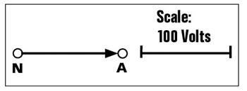
Figure 1. Phasor diagram of a single-phase, two-wire, 120-volt service
Hot means “energized.” The IEEE® Authoritative Dictionary of IEEE® Standard Terms defines energized as “Electrically connected to a source of potential difference, or electrically charged so as to have a potential difference from that of ground.” The term phase also is commonly used to identify a conductor that is energized. It is very important to understand that the conductor I am referring to as a phase wire or hot wire is the conductor you do not want to touch if you are standing barefoot on the ground. The neutral conductor is the conductor that carries some or all of the current back to the source. When the neutral conductor is grounded at the utility’s source transformer and at the customer’s load center some of the return current flows from the load center back to the source transformer through the ground.
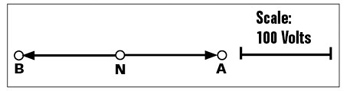
Figure 2. Phasor diagram of a single-phase three-wire, 120/240-volt service
A single-phase, two-wire, 120-volt service to a small load like a sign would have the phasor diagram, as shown in figure 1, representing the voltage between the phase wire or hot wire and the neutral conductor.
Note that the pointer end of the phasor is labeled “A” to identify it as the phase conductor or hot wire. The other end of the phasor is labeled “N” to identify it as the neutral conductor. For this diagram, the length of the phasor is 1.2 inches long to represent a voltage magnitude of 120 volts. In this case, the scale I am using to draw the phasor diagram is 1 inch equals 100 volts. For this type of service, there are usually two conductors between the utility’s source transformer and the customer’s load center, one phase conductor and one neutral conductor. This type of service is used to serve 120-volt single-phase loads. The phase conductor carries all the load current. The neutral conductor is usually grounded at the source transformer and at the customer’s load center.
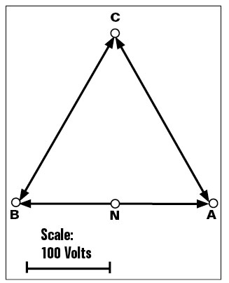
Figure 3. Phasor diagram of a three-phase, four-wire, 120/240-volt delta service
A typical single-phase three-wire, 120/240-volt service to a residence or small commercial establishment is shown in figure 2.
In this diagram, there are two hot wires. The phase angle of one is 180° out of phase with the other. Note that the pointer end of one phasor is labeled “A” and the pointer end of the other phasor is labeled “B” to identify the two hot wires as different phases. The voltage between “A” phase conductor and neutral conductor is 120 volts. The voltage between “B” phase conductor and the neutral conductor is 120 volts. The voltage between “A” phase conductor and “B” phase conductor is 240 volts. For this type of service, there are usually three conductors between the utility’s source transformer and the customer’s load center: two phase conductors and one neutral conductor. This type of service is used to serve both 120-volt and 240-volt single-phase loads. Each phase conductor carries the current associated with the 240-volt loads plus the current associated with the 120-volt loads connected to that phase. The neutral conductor is usually grounded at the utility’s source transformer and at the customer’s load center. The total current that is shared by the neutral conductor and the ground is the difference between the two phase currents. For example, if phase A is carrying 100 amps and phase B is carrying 80 amps, the total neutral current will be 20 amps.
A typical three-phase four-wire, 120/240-volt delta service, usually to a small commercial establishment is shown in figure 3.
In this diagram, there are three hot wires. The hot wires are labeled “A,” “B,” and “C” to identify them as different phases. The phases are 120° apart. The phase-to-phase voltages are all 240 volts. The phase to neutral voltages for “A” and “B” phases are 120 volts. The phase-to-neutral voltage for “C” phase is 208 volts. Because the phase-to-neutral voltage is higher on the “C” phase, this conductor is often referred to as the high leg. From the phasor diagram, you can see why this service voltage is called a delta source. For this type of service, there are usually four conductors between the utility’s source transformers and the customer’s load center: three phase conductors and one neutral conductor. This type of service is used to serve three-phase three-wire 240-volt loads, single-phase two-wire 120-volt loads and/or single-phase two-wire 240-volt loads. The neutral conductor is usually grounded at the utility’s source transformer bank and at the customer’s load center. The total current that is shared by the neutral conductor and the ground is the difference between “A” phase and “B” phase currents.
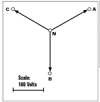
Figure 4. Phasor diagram of a three-phase four-wire 120/208-volt service
A typical three-phase four-wire 120/208-volt “Y” service, usually to a commercial establishment is shown in figure 4.
In this diagram, there are three hot wires. The hot wires are labeled “A,” “B,” and “C” to identify them as different phases. The phases are 120° apart. The phase-to-phase voltages are all 208 volts. The phase-to-neutral voltages are all 120 volts. From the phasor diagram, you can see why this service voltage is called a “Y” source. For this type of service there are usually four conductors between the utility’s source transformers and the customer’s load center: three phase conductors and one neutral conductor. This type of service is used to serve three-phase three-wire 208-volt loads and/or single-phase two-wire 120-volt loads.
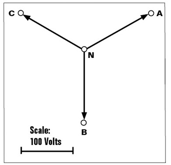
Figure 5. Phasor diagram of a three-phase four-wire 277/480-volt service
A typical three-phase four-wire 277/480-volt “Y” service, usually to a large commercial or industrial establishment, is shown in figure 5.
In this diagram, there are three hot wires. The hot wires are labeled “A,” “B,” and “C” to identify them as different phases. The phases are 120° apart. The phase-to-phase voltages are all 480 volts. The phase-to-neutral voltages are all 277 volts. From the phasor diagram, you can see why this service voltage is called a “Y” source. For this type of service, there are usually four conductors between the utility’s source transformers and the customer’s load center: three phase conductors and one neutral conductor. This type of service is used to serve three-phase three-wire 480-volt loads and/or single-phase two-wire 277-volt loads.