Well, not exactly. Yes, all of those things will usually keep a system uses sunlight for fuel. However, these and other weather conditions also affect how a PV system is designed and installed to comply with the requirements of the National Electrical Code. With a PV power system lifetime exceeding 40 years, Mother Nature is going to use every trick in the book to make that system fail before its time. PV designers, installers, and inspectors need to devote significant attention to the weather-related safety requirements for PV systems to help ensure long-lived, hazard-free electrical installations.
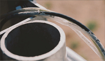
Photo 1. THHN conductors exposed to sunlight
Intense Solar Radiation and High Temperatures
Before we look at the dark side of PV, let’s examine hot and sunny. PV modules are designed to operate in sunlight and the more sunlight they get, the more power and energy they will produce. The “Perspectives on PV” article in the July-August 2004 IAEI News (available on the SWTDI web site) addressed how the PV module’s electrical output is affected by the intensity of the solar radiation. But what about the related issues of the effects of temperature and ultra-violet radiation on the other equipment? Any equipment exposed to the sunlit environment should be rated for the exposure. Exposed conductors and cables must be marked sunlight resistant (UF and TC cables) or be tested during the listing process for UV exposure (USE and SE, Table 310.13) cables. Using the wrong conductors can lead to failures (photo 1). Because of the normal operating environment, cables attached to PV modules must be listed for wet (the W designator) and hot environments (the HH designator) and a -2 after the cable type gets them both. We have tested PV installations that have been in hot, sunny, dry weather for two weeks or more, opened module j-boxes and conduit bodies and had hot water run out. -2 cables are a must.
Underwriters Laboratory is releasing a specification for a new “PV” cable. Cables meeting this specification will have to pass a 720-hour accelerated UV exposure test, be rated for wet locations, have at least a 90°C rated insulation, have a flame retardant compound, and have a physically tougher insulation than type USE cable. Although the intent of the specification was that compliant cables would now meet the requirements for use in ungrounded PV systems as permitted by Section 690.35 of the NEC, it has yet to be determined how the “PV” cable will be used, given the existing code language in 690.35(D). The issue will hopefully be clarified in the 2008 NEC and the PV industry is looking at ways to use this cable long before the 2008 Code is enacted. Enlightened electrical inspectors who may see the new cable as an acceptable alternative to USE-2 may be the key to early its adoption.
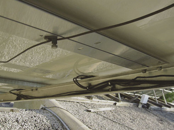
Photo 2. Pipe clamps with inserts holding cables securely
Cord grips and cable clamps used on outdoor junction boxes should be UV rated. In some cases, metal cord grips have been used, and while metal is resistant to UV, these generally have not been listed for outdoor use because they can corrode rapidly. Nylon cable ties are frequently used to tie conduits and exposed cables to module racks. The white cable ties have no UV resistance, and even some of those that are black fail in a few months. The use of listed cable ties specifically marked (at least on the package) for outdoor use and sunlight resistance should be encouraged. Even better is the use of stainless steel pipe clamps with neoprene rubber inserts to firmly secure exposed single conductor cables to racks and frames (photo 2).
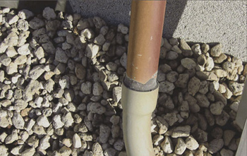
Photo 3. PVC conduit and cement darkened with age
The Fine Print Note No. 2 in 310.10 of the 2005 NEC points out that conduits on buildings in sunlight operate at temperatures of 17°C above the ambient temperatures. Because conduits in PV systems are exposed to sunlight for decades, the raceways many times become discolored or darken with age (photo 3). Therefore, I suggest to the PV installers that 20°C be added to the highest ambient temperature when doing ampacity calculations, to account for the higher solar energy absorption of the aged materials. With PV module junction boxes operating in the 65–75°C (and hotter) ranges and conduits in sun in ambient temperatures of 40–50°C plus the added 20°C for solar heating, it becomes evident that 310.15 temperature corrections are critical in calculating ampacities of wiring for PV systems.
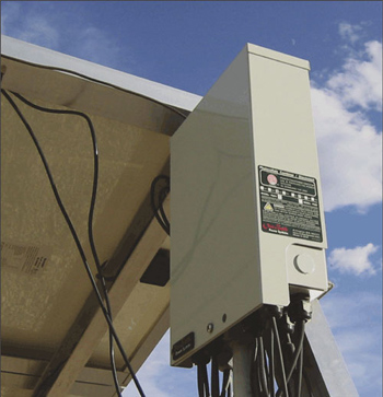
Photo 4. PV combiner in the sun
PV combiner boxes that combine the outputs of strings of PV modules are also mounted in the sun. These devices (photo 4) usually contain overcurrent devices, and most overcurrent devices are rated for operation in ambient temperatures up to 40°C. With ambient temperatures in many locations of 40°C (45–50°C in the Southwest), solar heating of these enclosures pushes the internal temperature well above 40°C. The overcurrent device manufacturer must be consulted for appropriate temperature corrections. After applying the corrections by increasing the rating of the overcurrent device, the installer must then go back and verify that conductors and modules are properly protected from fault currents.
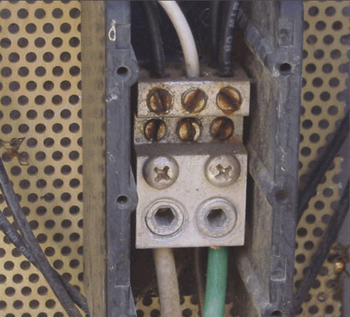
We also have to deal with those often overlooked terminal temperature limitations in NEC 110.14(C) because the high PV module temperatures require the PV installer to use 90°C rated conductors. While the modules all have terminals rated for use with 90°C conductors, the combiner boxes and most of the other fused disconnects and overcurrent devices have terminals that are restricted to use with 60°C or 75°C rated conductors. Some of the combiner boxes do not have temperature markings, and since the overcurrent devices are usually below 100 amps, a conductor temperature limitation of 60°C must be assumed. Things get pretty
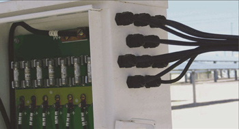
Photo 5. PV combiner in shade
complex when we deal with a fused combiner box, for example, with unmarked terminal temperature limitations. Consider one operating in the sun in Phoenix, Arizona, where the ambient temperature may be 45°C for weeks at a time. The box temperature could be 55–60°C (requiring 90°C insulated conductors), the fuse rating must be temperature corrected for the 55–60°C operating temperature, and then the operating temperature of the conductor/terminal at these elevated temperatures must be estimated to be less than 60°C. Obviously, if the internal temperature of the enclosure is near 60°C, it is going to be difficult to have fuse terminals operating below 60°C with any appreciable current in the terminals. In this case, the prudent path would be to replace this PV combiner with one that is marked for use with 75°C insulated conductors. At the very least, any enclosure containing overcurrent devices installed in the hot Southwest (and other hot locations) should be mounted in the shade where it will be subjected to no more than the high ambient temperatures (photo 5).
Wind, Sleet, Snow and Rain
High winds are an issue in coastal areas where hurricanes are common as well as in many other areas of the country. Building codes in these areas generally specify how items on the roof and on the ground are to be fastened down to resist the lifting forces of the wind. The Study Guide for the North American Board of Certified Energy Practitioners (NABCEP) has some guidance for PV installers in this area that is based on information in the National Design Specification for wood construction and on roofing manuals. The Study Guide may be downloaded from the Resources section of the NABCEP web site (www.nabecp.org).
In areas of the country where there is snow buildup on roofs, attention must be directed to securely fastening all conductors and cables to the module racks or mounts and to the roof. Otherwise, sliding snow can rip wires loose and pull conduits loose. Similar attention to these workmanship details should be applied to windy areas and in all installations, a neat, workman-like installation will usually be safer that a messy installation (photo 2).
The PV designer/installer will usually be required to make a tradeoff between the best tilt angle for PV array performance and the angle that will best shed snow. Fortunately, as the installation location moves farther north (into snow country), the tilt angle for best performance gets greater and even assists in shedding snow. However, these higher tilt angles usually result in the PV modules being subjected to higher wind loading, so secure mounting is a must.
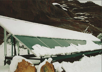
Photo 7. Too much snow means no juice (Photo courtesy of NREL)
At very low temperatures, snow, sleet and freezing rain may adhere to the PV modules and must be removed if full output from the PV system is desired (photo 7). Obviously rooftop installations may make this more difficult. On the other hand, ground-mounted arrays must be high enough to avoid deep snow and drifts.
Hail? Usually, hail doesn’t pose too much of a problem. The PV modules are made with tempered glass and the modules are tested with impacts simulating hailstones.
Summary
Yes, sleet, snow, rain, and the dark of night will prevent a PV system from producing energy. But when the snow melts and the sun comes up, that PV system will again be generating power for a very, very long time. The wide range of environmental conditions in which PV systems are installed impose significant design and installation requirements. The NEC has been addressing such requirements for many years. The long life of these systems points to the need for durable hardware and high levels of workmanship. The equipment is required to be up to the task. Installers and inspectors must also be up to the job.
For Additional Information
If this article has raised questions, do not hesitate to contact the author by phone or e-mail. E-mail: jwiles@nmsu.edu Phone: 505-646-6105
A PV Systems Inspector/Installer Checklist will be sent via e-mail to those requesting it. A color copy of the 143-page, 2005 edition of the Photovoltaic Power Systems and the National Electrical Code: Suggested Practices, published by Sandia National Laboratories and written by the author, may be downloaded from this web site: (http://www.nmsu.edu/~tdi/roswell-8opt.pdf. ) A black and white printed copy will be mailed to those requesting a copy via e-mail if a shipping address is included. The Southwest Technology Development web site (http://www.nmsu.edu/~tdi) maintains all copies of the previous “”Perspectives on PV”” articles. Copies of “”Code Corner “” written by the author and published in Home Power Magazine over the last 10 years are also available on this web site.
Draft proposals for the 2008 NEC being developed by the PV Industry Forum may be downloaded from this web site: http://www.nmsu.edu/~tdi/pdf-resources/2008NECproposals2.pdf
The author makes 6–8 hour presentations on “”PV Systems and the NEC”” to groups of 40 or more inspectors, electricians, electrical contractors, and PV professionals for a very nominal cost on an as-requested basis. A schedule of future presentations can be found on the SWTDI web site.