The grounding of electrical circuits and systems and the bonding of conductive components of an electrical installation have generally remained the same from a technical basis for many decades. In spite of this, the subject remains one of continual misunderstanding and controversy in the electrical community. This is even more exacerbated when these basic requirements are applied to the installation of a PV system. This article is intended to assist in adding clarity of both the understanding and the installation of these systems and also to give some insight of some important changes to these requirements that are being considered for the 2017 NEC.
Let’s begin with Section 90.3 of the NEC to clarify that the basic requirements for grounding and bonding are covered in Article 250; and thus as described in 90.3, all of the requirements in Chapters 1 through 4 apply generally to all electrical installations. Section 90.3 goes on to state that Chapters 5, 6 and 7 apply to specific installations, equipment, and systems; and thus they can modify or supplement the requirements located in Chapters 1 through 4. This is certainly the case with PV systems that are predominately covered in Article 690, and that article has some specific additions and modifications as applied to the grounding and bonding of PV systems and equipment.
One of the first differences is the general requirements found in Section 250.6 (A) for grounded systems and (B) for ungrounded systems. In this section, the concepts for limiting potential between electrical equipment and ground and providing a proper ground-fault current path are unveiled. There are portions of a PV system where these requirements may be useful, such as a dc, PV inverter located in a location where contact with it and earth are likely. However, when dealing with PV systems, there are many times when earth contact is not a consideration. In addition PV systems, in general, will not provide sufficient fault currents to open conventional overcurrent devices. That being said, PV equipment needs to be properly bonded so that the low current flows on metal parts can open smaller string level overcurrent devices, if installed, and also facilitate the operation of dc ground-fault protective devices.
One very important section of Article 250 is 250.8 where a list of acceptable termination devices for grounding and bonding connections is established. It is very important to note that 250.8(A)(8) states “Other listed means” as this allows for connection devices that are listed for use and that are not defined in the prescribed list as this list is not intended to be all-inclusive nor to limit new or different technologies.
Article 250 then goes into the requirements of which systems must be grounded, may be grounded, and cannot be grounded. Article 690 goes down an entirely different track here as it allows either grounded systems or ungrounded systems, and then it covers bonding and grounding requirements for the equipment and type of system installed. So now let’s move into some of the specific requirements in Article 690. We will revisit Article 250 a little later when discussing some sizing and physical protection requirements.
The specific bonding and grounding requirements for PV systems in Article 690 are in Part V.
System Grounding
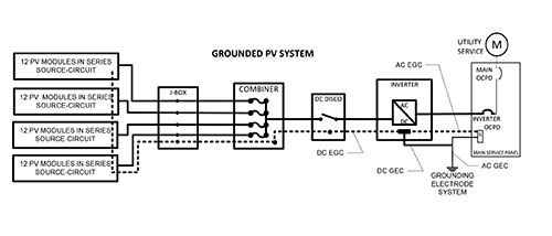
Section 690.41 covers system grounding, allowing both grounded and ungrounded PV array conductors. Both types of systems require ground-fault detection on the PV source and output circuit conductors [690.5 and 690.35(C)] with one very restrictive exception. The only PV system that would not require ground-fault protection is a small PV system, with no more than two source circuits where all the dc conductors are not installed on buildings [690.5 Exception]. The 2014 NEC further clarifies in 690.5 that ground-fault detection in grounded PV systems must detect ground faults in intentionally grounded conductors. Grounded PV inverters, to be compliant with the 2014 NEC, must either be augmented with external ground-fault detection equipment that meets this new requirement or be certified to detect faults in the grounded conductor. Few, if any, grounded inverters manufactured prior to 2014 have this capability. A few grounded inverters are starting to market that they are capable, but many have not been updated to address this new specific requirement.
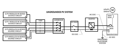
The good news on the issue of ground-fault detection is that a large percentage of new inverters being installed today have non-isolated ac output circuits. What this means is that the ac output of the inverter does not pass through an isolation transformer the way most grounded dc inverters do. PV systems with grounded dc PV arrays must have an isolation transformer to isolate the grounded dc array from the grounded ac service conductors that it is connected to on the output of the inverter. With a non-isolated inverter, the lack of isolation to the grounded ac service conductors requires that the dc PV array be ungrounded for the inverter to work. While this type of system is operating, the dc PV array actually becomes referenced to ground through the ac output conductors. The PV industry often refers to this system configuration as “ungrounded,” but in reality the PV array is only ungrounded when the inverter is not operating. As soon as the inverter begins producing power, the whole system becomes referenced to ground through the ac service conductors. The only time a non-isolated inverter would truly be in an ungrounded PV system is if it were installed on an ungrounded delta service. Some non-isolated inverters sold in the United States are not certified to be installed on ungrounded delta services.
The location where grounded PV system conductors must be grounded is covered in 690.42. It states that a grounded PV array must be grounded at the ground-fault protection device—and at no other location. Since nearly all PV systems have ground-fault detectors in or at the inverter, the requirement is actually in the exception, which can be confusing. The First Revision of the 2017 NEC places this requirement in positive language, rather than as an exception. The informational note in 690.42 states that grounding a PV array close to the PV array makes the system less susceptible to lightning. This note is not always true and has been eliminated from the 2017 First Revision language. Don’t forget that these requirements all deal with “system grounding” and many systems that are being designed and installed today are ungrounded systems. As we go into the next section, “Equipment Grounding,” we will separate the two and the importance of proper equipment bonding with a reference to ground at the location where the transition is made from the dc system to the ac system. The required dc ground–fault protection device is usually at this location as well.
Equipment Bonding and Grounding
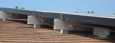
Equipment grounding requirements for PV systems are covered in 690.43. These requirements include the bonding and grounding requirements for exposed metal parts of PV systems such as metallic module frames, electrical equipment, and conductor enclosures [690.43(A)]. Since the PV array and other electrical equipment in PV system, e.g., inverters, are often located remotely from one another, 690.43(B) requires that an equipment grounding conductor (EGC) be run from the array to other associated equipment. Section 690.43(C) permits the support structure of a PV array to be used as an EGC provided that it has been either, 1) listed for equipment grounding or 2) includes bonding jumpers between “separate metallic sections” of the structure. Section 690.43(D) and (E) specifically allow for listed and identified bonding and grounding components to be used for mounting PV modules, bonding PV modules to array structures, and bonding adjacent modules to one another. It is important to understand that this conductor (or these conductors) are really bonding conductors to keep all exposed metal parts at the same potential and to allow ground–fault detection devices to recognize improper current flow in the interconnected path to ground and open the protective device. Do not make the mistake that many have made and consider these bonding conductors as being equivalent to service line side bonding conductors. These conductors will never see currents in the same magnitude to which service bonding conductors could potentially be exposed.
All these references to listed and identified bonding and grounding equipment beg the question, “How are products listed and identified as bonding and grounding equipment?” UL 1703 is the safety standard for PV modules, and bonding–and-grounding hardware could be included with the PV module as part of the module listing. It is very rare for currently available PV module products to include any grounding hardware. The UL 1703 standard does allow for PV modules and panels to be grounded with listed grounding devices.
Until recently, grounding devices could be certified to a few standards which included UL 1703; UL 467, Grounding and Bonding Equipment; and, subject UL 2703, Mounting Systems, Mounting Devices, Clamping/Retention Devices, and Ground Lugs for Use with Flat-Plate Photovoltaic Modules and Panels. UL 2703 recently was elevated from draft standard status to a full ANSI-accredited national standard like UL 467 and UL 1703. The UL 2703 standard is intended to cover all equipment related to bonding and grounding of PV modules and their support structures. As of this publication date, over a dozen different grounding devices, and more than a dozen support structures are certified to UL 2703. This is a promising and helpful development for contractors and AHJs who are required to install and inspect PV systems in compliance with 690.43.
While it is the intention of the standards process that all bonding and grounding equipment for PV modules and support structures be certified to UL 2703, there is a transitional period currently where an AHJ can and should be willing to approve products certified to UL 467. The key differences between UL 467 and UL 2703 are that UL 2703 specifically requires that a grounding device specify what materials the device is certified to attach to, and UL 2703 also requires environmental tests that certify outdoor use. While UL 467 allows manufacturers to perform additional tests to show that a product is suitable for outdoor use and is compatible with certain materials, UL 467 does not specifically evaluate for those conditions. The difference between UL 467 and UL 2703 is that a UL 467 device puts the onus on the contractor and AHJ to evaluate that the product is suitable for aboveground outdoor use and is compatible with the surface it is attached to. The guide card information for UL 467 clearly states that UL 2703 is the specific standard to use for PV modules moving forward. Over the coming year, it is likely that the availability of UL 2703 products will be sufficient so that reviewing UL 467 devices will be unnecessary.
Myth—all grounding lugs must be tested with each PV module individually
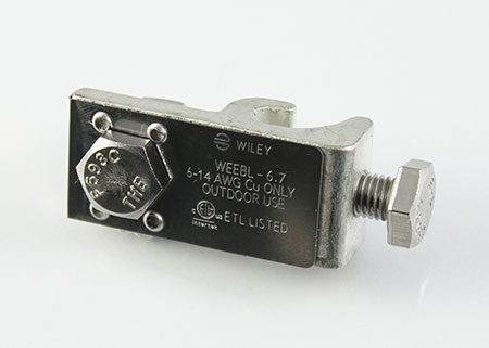
There is a bit of a myth that all grounding devices must be tested individually with every PV module on the market. One of the key benefits of UL 2703 is that it allows for the evaluation of bonding and grounding devices for various thicknesses of metals and types of coatings on metals. One benefit of aluminum PV module frames is that the material is reasonably soft and so bonding devices that require penetrating the anodized or oxidized aluminum surface can do so fairly easy. Products, such as the ILSCO SGB-4 grounding lug, have been certified to UL 2703 to provide bonding and grounding of any flat aluminum material that is 1/64″ thick to ¼″ thick, that has normal anodized or oxide coatings. Burndy has the WEEBL-6.7 grounding lug product that can be installed on unused mounting holes of PV modules to connect the module frame to the equipment grounding conductor. These two companies are the largest suppliers of the bonding and grounding devices in the United States and are heavily involved in developing products for the PV industry. In addition, the largest and most established PV modules racking manufacturers all have various products certified to UL 2703.

Fortunately, the days of running bare copper equipment grounding conductors all over aluminum PV arrays are quickly coming to an end. While many in the electrical installation and enforcement community may view this change with skepticism, it is crucial to understand major improvements that UL 2703 certified devices are bringing to the safety of PV systems. Not only are bare copper conductors not supposed to come in direct contact with aluminum—which is common in older PV arrays—but the grounding path that the copper conductor provides is not as good as a UL 2703 certified structure. Think of it in this context, a PV array where each module is bonded at four points is more reliable than a PV module bonded at a single point. A PV array section with hundreds of grounding paths—as with a fully bonded array—versus a single copper wire has much less resistance to earth. Recent field testing performed on a UL 2703 array showed that the UL 2703 method had much lower ground path resistance than the same array using a bare copper EGC. Lower ground path resistance means better operation of ground-fault detectors and safer installations. Redundant ground paths mean that a single failure, or even many failures, is unlikely to result in a loss of bonding and grounding.
Sizing of EGCs in a PV Array
Sections 690.45 and 690.46 cover the sizing and protection of EGCs within a PV array. Since nearly all PV systems are required to have ground-fault protection, 690.45 references 250.122 for the minimum sizing of the EGC. The size of the EGC for a PV circuit is based on the size of the overcurrent device protecting the circuit as shown in Table 250.122. Section 690.45 also sets the lower size limit to 14 AWG and does not require that the size of the EGC be increased to address voltage-drop issues. The reason voltage drop is not a consideration is that ground-fault detectors are required to operate with currents of 5 amps or less, making voltage–drop adjustments on these conductors unnecessary.
Section 690.46 addresses protection of EGCs within a PV array. The need for protection can often require a subjective evaluation as to whether an EGC is exposed to physical damage.
Section 690.46 references 250.120(C), which requires EGCs smaller than 6 AWG to be protected from physical damage with a raceway, cable armor, or installed in hollow structural spaces or not exposed to physical damage. Some PV mounting systems have open cavities that could protect smaller conductors. However, if conductors have to be run exposed where they could be a trip hazard or have other physical damage, it is appropriate to protect the EGC with a raceway or to install a 6 AWG EGC that does not require physical protection.
Grounding Electrode Systems and PV Systems
Section 690.47 covers the requirements for grounding electrode systems in PV systems. This section has seen many changes over the 30 years that Article 690 has been in the NEC (yes, Article 690 was introduced in the 1984 NEC). In the 1980s, most PV systems were installed in remote locations where no utility service was available. While this still makes up a small percentage of new installations, the vast majority of PV systems are installed connected with utility services. The grounding electrode system requirements of Article 250 govern how these electrode systems must be installed. A quick review of the grounding electrode system requirements of Article 250 show that all electrical systems require a grounding electrode system. The size of the electrode system is a function of the size of the service conductors [250.66].
While a PV system may be an additional electrical supply to a building, most PV systems are not configured to operate any electrical loads directly. In fact, most PV systems are simply a supply of current to the electrical distribution equipment in a building, reducing the amount of current supplied by the service conductors. For most systems, a utility outage instantly shuts down the PV system, preventing it from continuing to supply current to the building. Only in the case of specially designed PV systems configured to operate additionally as an optional standby system can a PV system provide backup power. Fewer than 2% of PV systems currently are configured in this manner.
Unless there is no existing power source, the existing grounding electrode system, required by Article 250 for the existing power source, is used for the PV system. For PV systems on buildings with no other power source, if the PV system is supplying power to dc loads, Section 250.166 governs the sizing of grounding electrode system; if the PV system is supplying power to ac loads, Section 250.66 governs the sizing of the grounding electrode system. Soares Book on Grounding states that Section 250.66 should be used for dc electrical systems where transients, such as lightning, are likely. This authoritative source shows that the requirements of 250.66 are intended to be more stringent than those of 250.166 which is permitted only for dc systems. Soares essentially recommends the use of 250.66 for all electrical systems, ac or dc, since most electrical systems are exposed to transients from time to time.
The 2014 NEC added a few key sentences to 690.47 to address ungrounded PV systems installed in accordance with 690.35. These ungrounded PV systems are not required to have a separate GEC running from the PV system to the grounding electrode system. Instead, 690.47(C)(3) states that the ac EGC on the inverter output circuit of an ungrounded system is used to provide the connection to ground for the EGC on the dc side of the inverter so that ground-fault protection works properly.
In summary, most grounded PV systems today install a grounding electrode conductor (GEC) from the PV inverter (location of the ground-fault protector) to the existing grounding electrode system for the building. Ungrounded PV systems do not require the installation of an additional GEC since the required ac EGC on the inverter output circuit meets the requirement. In the first revision of the 2017 NEC, Section 690.47 is further simplified to only require a GEC to be attached to solidly grounded PV systems. Solidly grounded PV systems are very rare in that they generally do not have ground-fault detectors and, therefore, are restricted to one or two source circuits separate from buildings as discussed earlier in this article.
690.47(D) Additional Auxiliary Electrodes for Array Grounding
The last issue related to grounding electrode systems in the 2014 NEC is Section 690.47(D), Additional Auxiliary Electrodes for Array Grounding. This section requires that an auxiliary array electrode be installed on some PV systems. The text of this section has caused confusion in the field as many have interpreted this section to apply to every PV array, with two exceptions. Exception No. 1 states that the additional electrode is not necessary when the array is integral with the load it is supplying, such as free standing traffic signal, area light, or similar equipment where the array is integral and only supplies that load. This assumes that the supplied load already has an electrode as required by Article 250.
Exception No. 2 states that an additional electrode is not necessary where the PV array is within six feet of the premises wiring electrode. Since most electrode systems for buildings are installed within six feet of the premises, it follows that most roof-mounted PV systems on buildings with an existing premises wiring electrode would not require an additional array electrode. Only PV systems not installed on buildings, or installed on buildings without a local premises wiring electrode, or not integral with loads would require an additional auxiliary array electrode. In general, ground-mounted PV systems will require this additional electrode, and most roof-mounted PV systems will not require the electrode since most buildings already have a premises wiring electrode within six feet of the building. The 2014 language, however, does require a grounding electrode conductor to be run to the existing electrode; it just does not require the additional electrode. This is proposed to be changed to an option rather than a requirement in the 2017 NEC. The intent of this additional external connection was possibly to assist in dissipating lightning strikes on the array.
The final items in Part V of Article 690 relate to removal of modules [690.48], the removal of inverters [690.49], and equipment bonding jumpers [690.50]. The requirements of 690.48 and 690.49 require bonding jumpers to be installed when equipment is removed to ensure that grounded circuits do not become ungrounded during maintenance operations that might include replacement of PV modules or replacement of inverters. Since many of these maintenance activities often do not involve the AHJ, these provisions may be difficult or impossible to enforce. To that end, both of these sections are recommended for removal in the First Revision of the 2017 NEC. Section 690.50 simply states that equipment bonding jumpers in PV systems meet the requirements of 250.120(C) where the jumpers are smaller than 6 AWG.
Summary
Bonding and grounding of electrical equipment is a foundational requirement in the National Electrical Code and a major focus of those charged with enforcing the Code. The requirements of Article 690 modify the requirements of Article 250 in several ways as outlined in this article. The safety requirements related to bonding and grounding PV system equipment is experiencing dramatic improvements as products certified to UL 2703 become readily available. For the next year, products certified to UL 467 may be acceptable to AHJs provided the devices have been tested to verify use in aboveground, outdoor locations. Existing grounding electrode systems, common to most buildings with electrical circuits, provide an acceptable and sufficient electrode system with which to make required grounding connections for most PV systems. The 2017 NEC is working to simplify language related to bonding and grounding of PV systems to make the enforcement of these key requirements more straightforward. Remember that even though PV systems are separately derived systems as defined in the NEC, they do not directly tie into loads; and thus they do not have the same bonding and grounding requirements. Also, remember the difference between system grounding and the bonding and grounding of conductive metal parts and support members.