The National Electrical Code (NEC – NFPA 70) is, of course, a book of requirements dealing with the safe installation of electrical equipment and systems. However, photovoltaic (PV) electrical power systems are required to have additional levels of safety equipment over and above what is found in the typical dwelling. This is due to the high-voltage direct-current (dc) circuits and the electronic power processing equipment, as well as the extreme outdoor environment in which some of the equipment is mounted. Some equipment is required to reduce the potential for arcs and the resulting fires. Other equipment is pointed towards providing a safe environment for first responders (to fires) and a safe repair and service environment for the equipment and the nearby areas requiring maintenance (roofs, chimneys, etc.).
NEC Section 690.11, Arc-Fault Circuit Protection (Direct Current), establishes the requirement for a system that will detect and interrupt arcing faults that are due to connectivity failures (series circuit openings) in the dc PV circuits.
NEC Section 690.41(B), Ground-Fault Protection, establishes the requirements for a ground-fault detection and interruption system that operates on the dc circuits in a PV array. This is not a personnel shock protection system like the alternating current receptacle GFCI, but a system that will prevent sparks from arcs in the dc circuits that might start fires.
NEC Section 690.12, Rapid Shutdown of PV Systems on Buildings, requires a system that, when activated, can reduce the voltages of dc circuits between the array and the power conversion equipment to a safe level. This is the safety system that ensure the PV dc circuits are safe for first responders such as fire service personnel.
The Basics
Arc-Fault Circuit Protection. The arc-fault circuit protection devices are not only required by NEC Section 690.11 but also by UL Standard 1741, Inverters, Converters, Controllers and Interconnection System Equipment for Use With Distributed Energy Resources, for the inverter or equivalent equipment. Arc-fault circuit protection for dc circuits in the PV system is based on the test and evaluation requirements in UL Standard 1699(B). This is an extremely rigorous standard with arc-fault testing identical to arc faults that would be found in various sections of the PV array both close to the inverter in small PV systems with a few strings of modules and far away from the inverter in much larger PV systems with multiple strings.
NEC Section 690.11 requires that any PV system with an operating voltage of 80 V dc or greater between any two conductors shall be protected with a listed arc-fault circuit interrupter or other equivalent equipment. Arc-fault circuit protection is not required for PV arrays that are not mounted on or in buildings or for dc output circuits that are installed in metallic raceways or metallic enclosures. Detached structures used for the sole purpose of containing PV equipment are not considered buildings and are not required to meet the requirements of this section.
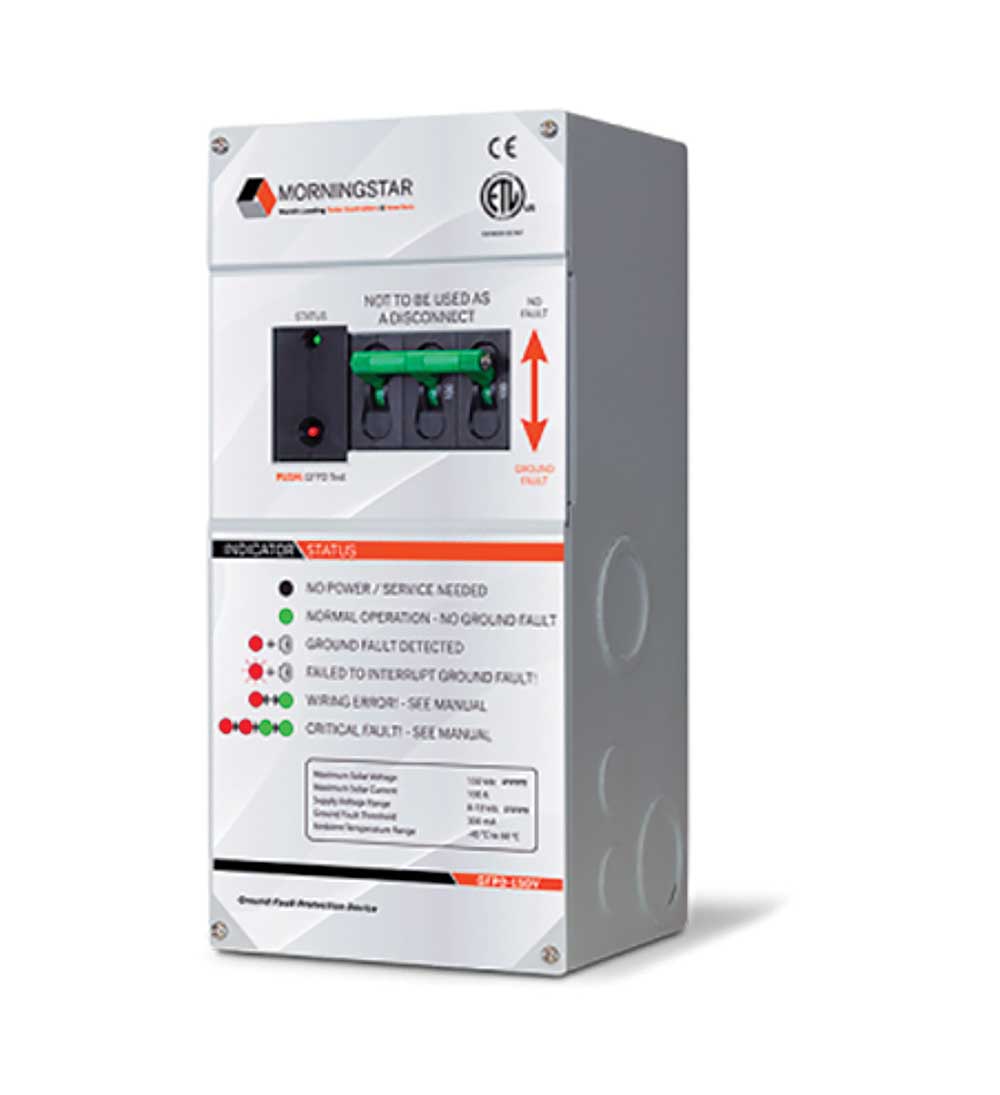
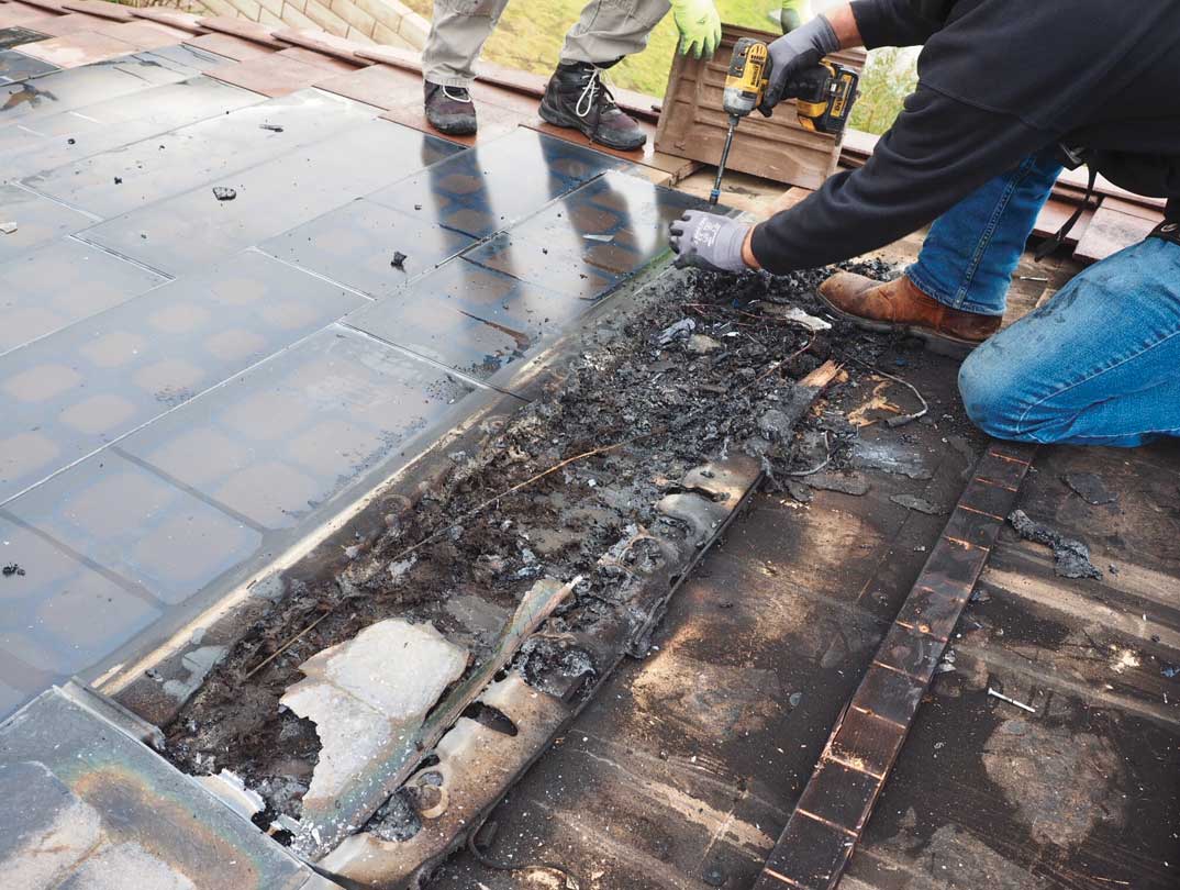
Ground Fault Protection. DC circuits, like ac circuits, are subjected to ground faults. The circuits may be in the array or the conductors from the array to the inverter or charge controller. In earlier implementations of this requirement, a single fuse or circuit breaker rated at .5 up to 4 A was used as the ground fault indicator and ground fault interrupter. Certain characteristics of larger PV systems indicated that ground faults were still possible and that this simple system was not sufficient. Now, most ground-fault detectors/interrupters (GFDI) are located inside the utility-interactive inverter or in standalone systems, possibly in an external device (photo 1). The GFDI will have an indicator on the front panel that a ground fault has been detected. It will turn off the inverter or similar equipment. The inverter must be manually restarted after the ground fault is corrected.
PV Rapid Shutdown System. The PV rapid shutdown system is a device or devices that control the voltage of various PV circuits when initiated by one or more initiation devices. Its purpose is to reduce shock hazards for firefighters. Ground-mounted PV systems and circuits from those systems that enter a building are not required to comply with section 690.12 if the sole purpose of that building is to contain PV equipment.
Several initiation devices are defined and allowed to make the use of this system readily available to first responders, including firefighters.
An array boundary is defined as 1 foot (305 mm) from the array in all directions. There are differing requirements for control of conductors depending on whether they are inside the array boundary or outside the array boundary.
Looking Deeper
Arc Fault Circuit Protection. In addition to the arcs caused by ground faults, two types of arc faults can occur in the dc wiring of PV systems. The first type of arc is when a wire is accidentally cut, a connection in a connector opens, or even a soldered connection in a PV module becomes unsoldered. These are arcs associated with a lack of connectivity and are also known as series arcs. The arc-fault protection devices required by section 690.11 must deal with series arcs only at this time. The other type of arc in PV wiring is the line-to-line parallel arc, where a positive conductor is accidentally or inadvertently touching a negative conductor.
The method of dealing with each of these arcs is entirely different. To deal with the series arc, the arcing circuit is opened, and no load (typically the inverter) is connected to the circuit. This reduces the current zero and, by doing so, extinguishes the arc. In a parallel arc, the typical solution is to short-circuit the positive and negative conductors yielding a lower impedance path for the current flow than through the arc. In both cases, the control of arcs must be done remotely, typically at the inverter. Arcing faults are detected by irregular current flow in the dc circuits or by a radio frequency (RF) signature associated with the arc transmitted through the conductors to the arc-sensing device.
In residential and moderately sized commercial PV systems, the arc-fault detection and interruption circuits are installed inside the inverter. In the very largest systems that come under the arc fault requirement, there may be additional arc-fault sensors and circuit interrupters in the array at locations remote from the inverter. UL Standard 1741 requires that the arc-fault detection system shut down the inverter when an arc fault is detected. A manual or automatic self-test function is required, and the standard requires a visual indicator that an arc fault has been detected. A manual restart is required.
At this time, there are no handheld arc-fault simulators that can be used to test the functioning of the arc-fault detection and interruption system on a PV system. Verification that the manual test function or the self-test function is working properly should be done on any system that has these functions.
Ground Fault Detection/Interruption System. The GFDI system is required to protect dc circuits that operate over 30 V or over 8 A [690.41(B)]. This system must detect ground faults in dc circuit conductors, including any functionally grounded conductors. The equipment must also be listed as providing ground fault protection for PV systems.
Electronic circuits in the inverters usually sense and detect ground faults by one of two methods. The conductors between the inverter and the PV array may be monitored during normal operation for equal current in both the positive and negative conductors. Any deviation from equal currents would indicate that currents are going into a ground fault. The other method is to monitor the impedance of each ungrounded conductor to ground. This is normally done as a part of the daily start-up routine for the inverter. A low value of resistance or impedance would indicate that there is a fault from one of the ungrounded conductors to ground.
When a ground fault is detected, the GFDI is required to either isolate/disconnect the faulted conductors or cease to supply power to the output circuits of the device containing the GFDI and interrupt the faulted dc circuits from ground reference in a functionally grounded system.
An Informational Note in 690.41(B)(3) says that the indicator may be anything from a light, digital indicator, display, or signal monitored by an alarm system or even a receipt of notification by web-based services.
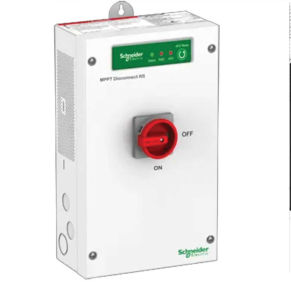
PV Rapid Shutdown System. The initiation device for the PV rapid shutdown system (PVRSS) may be one or more of three options. These options are the service disconnecting means, the PV system disconnecting means, or a readily accessible switch that plainly indicates whether it is in the OFF or ON position (photo 2). As required by 690.56(C), the OFF position should indicate that the array voltages have been controlled (the PV system is in a safe mode).
Although not currently required by the 2020 NEC, the author strongly feels that if a separate switch is required as the PV rapid shutdown initiator, that switch should be located adjacent to the required external emergency service disconnect (or whatever name that external service disconnect has in the 2023 NEC). See 230.85. Of course, if the service disconnect or a separate PV system disconnect is also the PV rapid shut down initiator, then the emergency service disconnect or that PV system disconnect would also be marked as a PV rapid shut down system initiator (690.56).
Controlled conductors include PV system dc circuits and inverter output circuits originating from inverters located within the array boundary and conductors outside the array boundary.
Controlled conductors outside the array boundary or more than one meter (3 ft) from the point of entry inside a building shall be limited to not more than 30 V within 30 seconds of rapid shut down initiation. Voltages will be measured between any two conductors and between any conductor and ground. These conductors could be dc circuits or ac circuits if they originate from inverters within the array boundary. This requirement means that the dc conductors outside of the array boundary must be controlled from voltage sources at both ends, the array end of the circuit and the inverter end of the circuit.
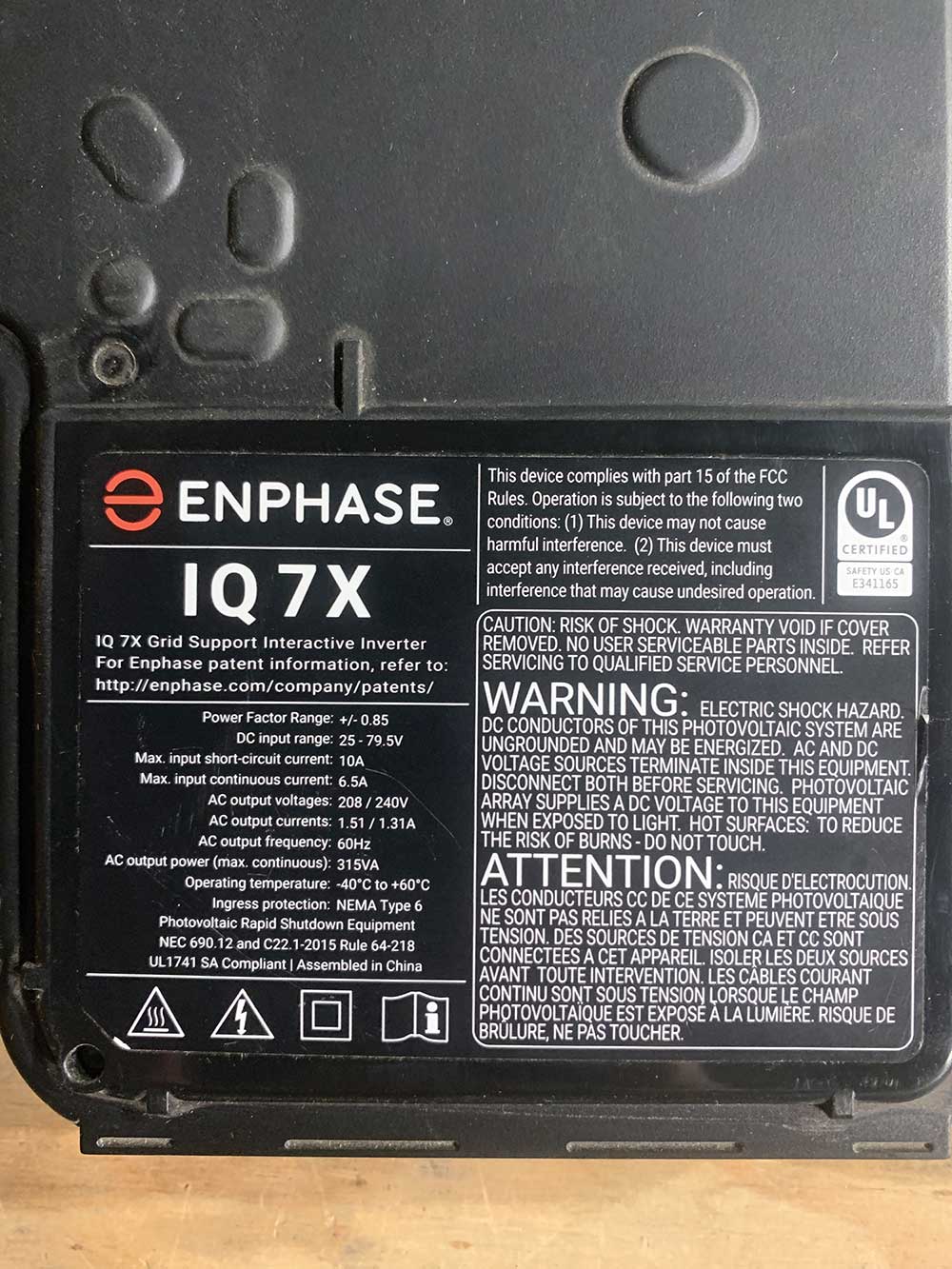
Inverters typically have energy storage or filter capacitors that can keep a disconnected (from the array) PV output circuit (aka the inverter dc input) energized for more than 30 seconds. This requirement would normally indicate that some sort of a PV rapid shutdown device would be needed at the array for each circuit leaving the array and also at the inverter if the inverter is not listed as PV rapid shutdown equipment (PVRSE). An inverter listed as PVRSE will, when the rapid shut down system is initiated, reduce the voltage at its dc input terminals to the required 30 V within 30 seconds. This PVRSE listed inverter will also reduce its ac output voltage to 30 volts or less within the 30 second period (see photo 2a). Of course, if the ac output circuit from the inverter to the point of connection with the utility service is energized by the utility, then a circuit breaker or disconnect for that output should be a part of the PV Rapid shutdown initiator system. Many utility-interactive inverters will initiate the PV rapid shutdown function when the utility power is lost, or a disconnect in the inverter ac output is opened. At the same time, the inverter will signal (by various methods) PVRSS equipment in the array to open circuits at that location.
Controlled conductors inside or within the array boundary shall be limited to not more than 80 V within 30 seconds of rapid shutdown initiation. Voltages will be measured between any two conductors and between any conductor and ground. Again, this would include dc conductors and ac conductors if the ac conductors originated from inverter outputs within the array boundary.
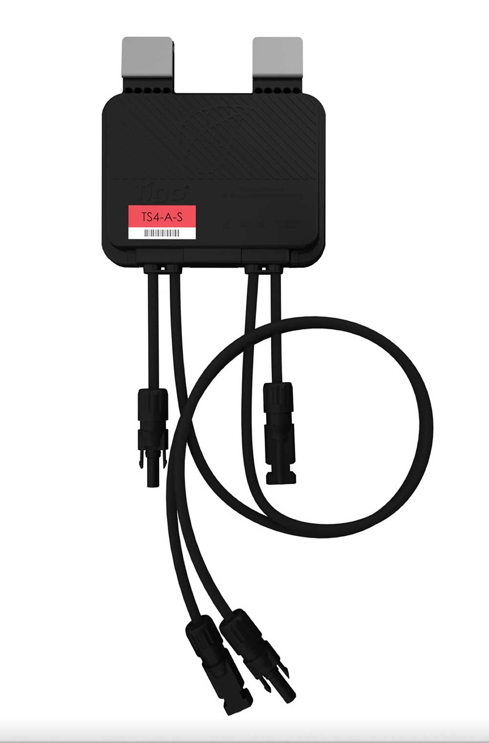
It should be noted that 80 V is above the open-circuit voltage of most currently available modules. However, a string of series-connected modules with a typical open-circuit voltage of 40-60 V or so would exceed the 80 V limit, and there may be a requirement for some type of rapid shutdown device on each module (or possibly pair of modules) so that the 80 V limit is not exceeded. PV dc-to-dc converters are available that include an input for a rapid shutdown initiator signal (see photo 3).
The output of a set of micro-inverters connected to each module with ac outputs within the array boundary would require those ac output conductors to be controlled. This is relatively easy since removing the ac power from these micro-inverters at an ac PV system disconnect switch would meet the requirement as long as the microinverters were listed as PVRSE. The anti-islanding requirements alone for inverters do not require that their outputs go to 30 volts or less within 30 seconds when the utility source is removed.
PV arrays with no exposed wiring methods or conductive parts and installed more than 2.5 m (8 ft) from exposed grounded conductive parts or ground meet the safety requirements of this Section 690.12. There is no required control of conductors within the array boundary [690.12(B)(2)(3)]. It should be noted that nearly all modules have exposed wiring to terminal boxes/junction boxes on their back surfaces, and there are no provisions for attaching conduits or other raceways to these modules. With this situation, it will be difficult to meet this allowance for an uncontrolled PV array. Even with this set of mounting and wiring method restrictions, Section 690.12(B)(1) still requires the control of conductors located outside the array boundary.
A new system defined as a PV Hazard Control System in Section 690.12(B)(2)(1) has been established by the Code and by a UL standard as a listed PV system that can be made essentially hazard-free to fire service personnel when placed into a hazard-free state by a PV rapid shutdown system initiator. This hazard control system may be a single device or multiple devices, and to the author’s knowledge, such a system has not been listed. The requirements for this system upon the various components, including modules, junction boxes, dc combiners, wiring methods, conductors, and other equipment at the PV array, are extremely restrictive.
The equipment that is used to perform the PV rapid shutdown functions other than initiation devices such as listed disconnecting switches, circuit breakers, or control switches is required to be listed for providing rapid shutdown protection.
Section 690.56(C) establishes the requirements for labels and diagrams on buildings that are equipped with PV systems that have a rapid shutdown system. Sections 705.10 and 712.10 have additional requirements for labeling. A permanent label located at each service equipment location to which PV systems are connected or an approved readily visible location must indicate the location of the rapid shutdown initiation devices. That label must include a diagram of a building with a roof, the location of the PV array on the roof and include the following words:
SOLAR PV SYSTEM IS EQUIPPED WITH RAPID SHUT DOWN.
TURN RAPID SHUT DOWN SWITCH TO THE “OFF” POSITION
TO SHUT DOWN PV SYSTEM AND REDUCE SHOCK HAZARD IN ARRAY
Where there are multiple PV arrays of a single roof, some with PVRSS and some older systems with no PVRSS, the rooftop diagrams must clearly show which PV arrays have a PVRSS and which do not.
As required by Section 690.56(C)(2), every rapid shut down initiator or switch must have a label with the following wording located on or no more than 1 m (3 ft) from the switch:
RAPID SHUT DOWN SWITCH
FOR SOLAR PV SYSTEM
Summary
The hundreds of participants involved with the development of the PV requirements in the National Electrical Code and in the development of UL Standards dealing with PV equipment should receive a hearty “Thanks” for keeping the installers, the owner/operators, and the firefighters who interact with PV systems safe with these safety systems that can reduce the potential for electric shocks and fires. While some of these systems are built into the various pieces of equipment, all must be installed following the requirements of the NEC and their listing and labeling instructions to achieve the maximum degree of safety.