Some of us, including inspectors, plan reviewers, electricians, and PV installers have been working with the Code for many years. We have seen the same Code requirements over and over again and have applied those requirements the same way in countless electrical installations. However, then comes along a Code change that clarifies and redefines those requirements in a way that encourages us to rethink what we have been doing all these years. Here is an example related to conductor ampacity calculations that have been in the Code for many years that were modified and clarified in the 2011 NEC and were further elaborated in the 2014 NEC.
For feeders from 215.2(A)(1) in the 2011 NEC:
“General. Feeder conductors shall have an ampacity not less than required to supply the load as calculated in Parts III, IV, and V of Article 220. The minimum feeder-circuit conductor size, before the application of any adjustment or correction factors, shall have an allowable ampacity not less than the noncontinuous load plus 125 percent of the continuous load.”
For branch circuits from 210.19(A)(1) in the 2011 NEC:
“General. Branch-circuit conductors shall have an ampacity not less than the maximum load to be served. Where a branch circuit supplies continuous loads or any combination of continuous and noncontinuous loads, the minimum branch-circuit conductor size, before the application of any adjustment or correction factors, shall have an allowable ampacity not less than the noncontinuous load plus 125 percent of the continuous load.
For PV dc circuits from 690.8(B) in the 2008 NEC:
“Ampacity and Overcurrent Device Ratings. Photovoltaic system currents shall be considered to be continuous
(1) Sizing of Conductors and Overcurrent Devices. The circuit conductors and overcurrent devices shall be sized to carry not less than 125 percent of the maximum currents as calculated in 690.8(A).”
Using those sections of the Code and a couple of others, many people involved with electrical power installations frequently applied that 125% factor to the continuous currents for the circuit and then additionally applied the conditions of use to the conductors involved in the process of sizing those conductors after using the 125% of the continuous load. This method of determining conductor sizing is understandable given the wording of the code for branch circuits and feeders where the phrase “before the application of any adjustment or correction factors.” The word “before” would seem to imply that after this 125% sizing calculation, the conditions of use adjustment factors and corrections should then be applied.
In Article 690, the PV calculations were even less clear because the application of the correction factors for conditions of use was not even mentioned. This caused many PV designers and installers to use the 125% factor on the maximum currents (these maximum currents are already 125% of the rated short-circuit currents for the dc PV circuits from the PV modules) and then apply the conditions of use factors to determine the conductor sizing.
Fortunately, the sequential application of the 125% factor and the conditions of use factors resulted in conductors that were sized with an additional safety factor not actually required by the Code. And, of course, the larger conductor sizes yielded lower voltage drops and less power loss.
After reviewing several articles written by Jim Pauley (Square D/Schneider Electric/NFPA) and others, the author proposed a clarification for the 2011 NEC that was accepted by Code-Making Panel 4. That section of code is now clarified as follows:
From 690.9 (B)(2) in the 2011 NEC:
“Conductor Ampacity. Circuit conductors shall be sized to carry not less than the larger of 690.8(B)(2)(a) or (2)(b).
(a) One hundred and twenty-five percent of the maximum currents calculated in 690.8(A) without any additional correction factors for conditions of use.
(b) The maximum currents calculated in 690.8(A) after conditions of use have been applied.
(c) The conductor selected, after application of conditions of use, shall be protected by the overcurrent protective device, where required.”
Not to be left behind, CMP 2 accepted similar proposals for Chapter 2 in the 2014 NEC.
For feeders from 215.2(A)(1) in the 2014NEC:
“General. Feeder conductors shall have an ampacity not less than required to supply the load as calculated in Parts III, IV, and V of Article 220. Conductors shall be sized to carry not less than the larger of 215.2(A)(1)(a) or (b).
(a) Where a feeder supplies continuous loads or any combination of continuous and noncontinuous loads, the minimum feeder conductor size shall have an allowable ampacity not less than the noncontinuous load plus 125 percent of the continuous load.
(b) The minimum feeder conductor size shall have an allowable ampacity not less than the maximum load to be served after the application of any adjustment or correction factors.”
For branch circuits from 210.19(A)(1) in the 2014 NEC:
“General. Branch-circuit conductors shall have an ampacity not less than the maximum load to be served. Conductors shall be sized to carry not less than the larger of 210.19(A)(1)(a) or (b).
(a) Where a branch circuit supplies continuous loads or any combination of continuous and noncontinuous loads, the minimum branch-circuit conductor size shall have an allowable ampacity not less than the noncontinuous load plus 125 percent of the continuous load.
(b) The minimum branch-circuit conductor size shall have an allowable ampacity not less than the maximum load to be served after the application of any adjustment or correction factors.”
So, now for both PV circuits and in conventional branch and feeder circuits we have clarified rules for determining conductor sizes. We are not to apply both the 125% and the conditions of use factors in the calculation. The Code requires us to calculate both factors independently and then choose the method that results in the largest conductor size.
The 125% factor
The requirement to use 125% of the continuous load (or 125% of the maximum current in PV DC circuits) has been with us for many years and was reportedly added to the Code to address nuisance operation of overcurrent devices in enclosures when conductors were operated at 100% ampacity continuously. The temperature rise associated with I2R losses in the conductors, and in the thermal overcurrent devices themselves were causing some of these devices to overheat and nuisance trip/blow. Using the 125% factor results in a conductor that is not loaded continuously at more than 80% of rating. Note 1.25 and .8 are mathematical reciprocals of each other (1/1.25 = 0.8 and 1/0.8 = 1.25), a fact that will be used below.
The Conditions of Use
As far as can be determined, the phrase “Conditions of Use” is not specifically defined in the Code, but most people involved in electrical installations using the NEC know what it means. And sometimes we see the phrase “normal conditions of use” and neither is that phrase defined. So what are they and how do they apply to the conductor sizing calculation? The definition of ampacity would be beneficial to this review.
From Article 100 in the 2014 NEC:
“Ampacity. The maximum current, in amperes, that a conductor can carry continuously under the conditions of use without exceeding its temperature rating.”
There are many conditions of use that can affect the ampacity of a conductor and these conditions of use must be applied to the determination of the size of a conductor. Some of them are:
- Air temperature around the conductor (referred to as ambient temperature)
- Number of conductors in a raceway or cable
- Sunlight exposure of the raceway or cable on or near roof surfaces
- Terminal temperature limitations of connected equipment
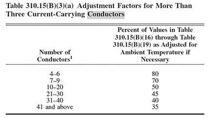
Some of these conditions of use give a fractional or decimal correction factor to be used to reduce the ampacity of an insulated conductor that is exposed to these conditions of use. For example, the temperature correction factors shown in NEC Table 310.15(B)(2)(a) are decimal numbers less than 1.0 when the temperatures are greater than 30 degrees Celsius (°C). And when the number of current-carrying conductors in a raceway or cable exceeds three, NEC Table 310.15(B)(3)(a) provides percentage adjustment factors for the conductor ampacities.
Note that normally, the ampacity from the ampacity tables would be adjusted downward by multiplying by the conditions of use factors. However, the same result can be obtained by dividing the continuous currents by the conditions of use factors. A quick check is to multiply the continuous load current by 125% (assuming no noncontinuous currents) and then compare that number with the continuous currents divided by the combined conditions of use factor. The larger of these two currents would be used to determine the conductor size.
Going back to the new way of sizing conductors above using the 125% factor or the conditions of use factors, we can use that reciprocal mathematical fact to ease the journey somewhat. If the circuit conductors are in a benign environment with no conditions of use factors that need to be applied, then the 125% of the continuous load current determines the conductor size.
However, when we start applying conditions of use, it pays to note how the numerical values combine. An ambient temperature factor might be 0.91 and with a conduit fill factor of 0.8 applied, the resulting combined factor is 0.91 x 0.80 = 0.728. That reciprocal relationship between 1.25 and 0.8 can be used. A combined conditions of use factor (with no other required corrections) of smaller than 0.8 would indicate that the conditions of use factor and not the 125% calculation should be used in determining the conductor size. Conversely, when the condition of use factor is larger than 0.8, then the 125% factor would be used to determine the conductor size. At a conditions of use factor of 0.8, both methods will give the same answer for conductor size due to that reciprocal relationship mentioned above.
It would take a large volume to examine and explain all these conditions of use, but some require a little more explanation when it comes to PV systems with their outdoor arrays of PV modules and exposed wiring that will have to endure the environment for 50 years or more.
Ambient Temperature
Although Section 310.15(B)(3)(b) has Informational Notes on ambient temperatures, many people will just use the local weather station data.
Informational Note: One source for the ambient temperatures in various locations is the ASHRAE Handbook — Fundamentals.
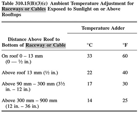
Informational Note to Table 310.15(B)(3)(c): The temperature adders in Table 310.15(B)(3)(c) are based on the measured temperature rise above the local climatic ambient temperatures due to sunlight heating.
Consideration should be given, when addressing PV circuits on the roofs of buildings that the local weather station may be at an airport outside the city and will be in a quite open area. The PV system may be installed in the city where the city heat bubble may increase ambient temperatures over the weather station measurement. And on a flat roofed building with parapets, the limited airflow may result in an increase in the ambient temperatures on the roof even more. These increases are before the application of any solar heating on conduits and should be considered when considering the 50-year life of a PV system in this environment.
What about the conductors and raceways behind those hot PV modules? If these conductors or raceways are within 3-4 inches of the backs of the PV modules, an ambient temperature of 75°C has been used in many parts of the country. If the conductors or raceways are spaced further away, then a 65°C ambient temperature may apply. Local situations may dictate different temperatures.
Raceways in Sunlight and Varying Conditions of Use
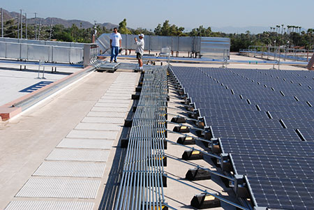
Suppose, for example, there is a large PV array being installed on a flat roof commercial building. Each PV source circuit (aka string of modules) requires two conductors (positive and negative) plus an equipment grounding conductor that will originate at the end of each module string and be routed to a dc combiner inside the building (out of the high temperature, sunlit rooftop location). Each of these three-conductor circuits is installed in an EMT raceway and there are 12 such circuits that are routed from the 12 module locations to a centrally located junction/pull box where all 12 circuits are routed into a single large EMT raceway with one equipment-grounding conductor (photo 1). That large raceway, now with 24 circuit conductors and one equipment-grounding conductor is routed across the roof and then down into the building where it terminates in the DC combiner.

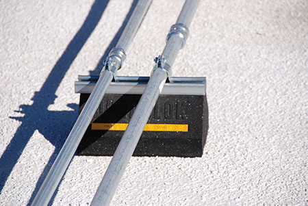
As the smaller and larger EMT raceways run across the roof, they are all subjected to a number of different environmental conditions. At times they are in the shade and are subject to the ambient temperature. At other times they are in the sun and may be 1/4 inches from the roof or 5 inches from the roof on standoffs or even 24 inches above the roof as they cross over HVAC ductwork (photo 2). Each of these environmental conditions must be addressed and will be coupled with the conduit fill factors that vary with each of these circuits in their run from the modules on the roof to the dc combiner.
Looking at the temperature adders in Table 310.15(B)(3)(c) and the conduit fill factors in Table 310.15(B)(3)(a) from the 2014 NEC will allow us to make the calculations.
If we look at these two tables, we find that the larger EMT raceway with a adjustment factor of 0.45 for the 24 circuit conductors in the shade is not as significantly impacted as the smaller EMT conduit with no conduit fill adjustment, where the smaller conduit is only 1/4 inch from the roof and the adder is 33 °C.
The PV source circuit conductors are typically 10 AWG USE-2 or PV wire. At an ambient temperature of 51°C (estimated roof ambient temperature), the temperature correction factor is 0.76 from Table 310.15(B)(2)(a). Adding 33°C, increases the temperature to 84°C and yields a correction factor of 0.29. This reduction yields a corrected ampacity for .29 x 40 = 11.6 amps. This reduction factor due to the conduit being close to the roof is more significant than the ampacity reduction due to conduit fill alone, which yields .45 x 40 = 18 amps. However, the large conduit may be in the sun and would be subject to both conduit fill and solar heating adjustments.
Looking at the larger conduit in the sun and 5 inches from the roof gives us the conduit fill correction of 0.45 and then with a temperature increase from 51 +17 = 68 °C, yields an additional correction factor of 0.58. Multiplying the two factors together gives us 0.45 x 0.58 = .261, and this is a more restrictive adjustment factor than the ½” conduit mounted against the roof and the ampacity is reduced (40 x .261 = 10.4 amps). So, it would appear that while all different conditions of use should be examined, the physics of the situation indicate that attention should be focused on the larger raceways containing more conductors in the sun. Plan reviewers could easily do these calculations, but unfortunately, this level of detail is not frequently found in the plans submitted with the permit application
Plan reviewers, inspectors and installers take note: In PV circuits, that old electrician’s “rule of thumb” of using a 30 amp fuse or breaker on a 10 AWG conductor is frequently not valid. Also, the fusing in dc combiners should be carefully calculated along with the size of these source circuit conductors as the PV module short circuit current continues to increase as larger and larger PV modules are being built.
The 10%, 10 foot Rule
Section 310.15(A)(2), from the 2014 NEC, may give some relief for the high temperature conditions on the roof.
“Selection of Ampacity. Where more than one ampacity applies for a given circuit length, the lowest value shall be used.
Exception: Where two different ampacities apply to adjacent portions of a circuit, the higher ampacity shall be permitted to be used beyond the point of transition, a distance equal to 3.0 m (10 ft) or 10 percent of the circuit length figured at the higher ampacity, whichever is less.”
On the roof with PV circuits, there are going to be several sections of the circuit that will have different calculated ampacities. If the worst case (lowest ampacity) section is less than 3.0 m (10 feet) in length or less than 10% of the length of the adjacent section with a higher ampacity (whichever is less), then the higher ampacity may be used for both sections. The Code uses the term “circuit length” and the example in the 2014 NEC Handbook uses a single hot section and then uses the entire circuit length to make the determination. In the PV environment, it appears reasonable to use just the length of the adjacent circuit with a higher ampacity as this section will be the heat sink for the shorter conductor.
If the most restrictive circuit section can be eliminated as the determining ampacity for the whole circuit, then the next most restrictive section should be examined in the same manner. Eventually, considering all conditions of use, an ampacity of the circuit will be determined. At that point, other factors such as terminal temperature limits should be considered.
Summary
New text in the 2011 and 2014 NEC has clarified and elaborated long-standing Code requirements and these new requirements may allow smaller conductors to be used than previously. Smaller conductors may reduce the cost of the electrical installation while still meeting safety requirements. With several different conditions of use applying to the dc circuits in a PV system mounted on the roof, ampacity calculations can be more complex if the most cost-effective installation can be made. These ampacity calculations may have to be reviewed in the field after the actual conditions of use have been identified.
For More Information
The author has retired from the Southwest Technology Development Institute at New Mexico State University, but is devoting about 25% of his time to PV activities in order to keep involved in writing these “Perspectives on PV’ articles in the IAEI News and to stay active in the NEC and UL Standards development. Seven to eight hour presentations are still available on PV and the Code and they cover 2008-2014 NEC requirements. He can be reached at: e-mail: jwiles@nmsu.edu, phone: 575-646-6105
The Southwest Technology Development Institute web site maintains a PV Systems Inspector/Installer Checklist and all copies of the previous “Perspectives on PV” articles for easy downloading. A color copy of the latest version (1.93) of the 150-page, Photovoltaic Power Systems and the 2005 National Electrical Code: Suggested Practices, written by the author, may be downloaded from this web site: http://www.nmsu.edu/~tdi/Photovoltaics/Codes-Stds/Codes-Stds.html.