There is no doubt that in electrical installations disconnecting means and overcurrent protective devices are required for electrical equipment and for ungrounded conductors. This fundamental criterion is reflected in Rule 14-010 of the CE Code as follows:
“14-010 Protective and control devices required
Electrical apparatus and ungrounded conductors shall, except as otherwise provided for in this Section or in other Sections dealing with specific equipment, be provided with
(a) devices for the purpose of automatically opening the electrical circuit thereto,
(i) if the current reaches a value that will produce a dangerous temperature in the apparatus or conductor; and
(ii) in the event of a ground fault, in accordance with Rule 14-102;
(b) manually operable control devices that will safely disconnect all ungrounded conductors of the circuit at the point of supply simultaneously, except for multi-wire branch circuits that supply only fixed lighting loads or non-split receptacles, and that have each lighting load or receptacle connected to the neutral and one ungrounded conductor; and
(c) devices that, when necessary, will open the electrical circuit thereto in the event of failure of voltage in such a circuit.”
In case of motors (rotating machines where location of disconnecting means is essential for safety), Rules 28-600 and 28-604 of the CE Code offer the following requirements for disconnecting means and for their location:
“28-600 Disconnecting means required
(1) Except as permitted by Subrules (2) and (3), a separate disconnecting means shall be provided for
(a) each motor branch circuit;
(b) each motor starter or controller; and
(c) each motor.
(2) A single disconnecting means shall be permitted to serve more than one of the functions described in Subrule (1).
(3) A single disconnecting means shall be permitted to serve two or more motors and their associated starting and control equipment grouped on a single branch circuit.”
“28-604 Location of disconnecting means
(1) The motor branch circuit disconnecting means described in Rule 28-602(1)(a), (b), (c), and (d) shall
(a) be located at the distribution centre from where the motor branch circuit originates; and
(b) where intended to serve as a single disconnecting means for a motor branch circuit, motor, and controller or starter, also be
(i) located in accordance with Subrule (3); or
(ii) capable of being locked in the open position by a lock-off device approved for the purpose and be clearly labelled to describe the load or loads connected.
(2) The motor branch circuit disconnecting means described in Rule 28-602(1)(f) shall be located in accordance with Subrule (3).
(3) Except as required in Subrule (5), the motor and motor starter or controller disconnecting means shall be located
(a) within sight of and within 9 m of the motor and the machinery driven by it; and
(b) within sight of and within 9 m of the motor starter or controller.
(4) Notwithstanding Subrule (3), where a motor or group of motors is fed from a single branch circuit in which the branch circuit disconnecting means is not capable of being acceptably locked in the open position and where the motor disconnecting means is a manually operable across-the-line type of motor starter, the motor disconnecting means shall be permitted to be located beyond the limits defined in Subrule (3), provided that
(a) it is capable of safely making and interrupting the locked rotor current of the connected load;
(b) it is capable of being locked in the open position; and
(c) it can be demonstrated that the location specified in Subrule (3) is clearly impracticable.
(5) The motor disconnecting means for air-conditioning and refrigeration equipment shall be located within sight of and within 3 m of the equipment.
(6) The disconnecting means shall be readily accessible or have the means for operating them readily accessible.
(7) Motor-driven machinery of a movable or portable type for industrial use shall have a motor-circuit switch or circuit breaker mounted on the machine and accessible to the operator”.
And what about generators?
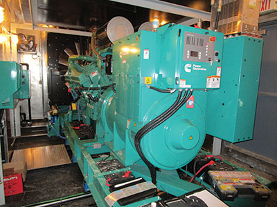
Each motor and generator is designed, constructed and certified to the CSA standard C22.2 No. 100 “Motors and Generators”. Scope of the standard states the following:
“Scope
1.1 This Standard applies to electric motors and generators for installation and use, in accordance with the Rules of the Canadian Electrical Code, Part I, in non-hazardous locations.
Note: The term “machine” throughout this Standard should be assumed to mean “motor” and “generator”.
In accordance with this CSA standard, some generators could be constructed with integral disconnecting means, and in this case the CE Code does not mandate a field installation of such disconnecting means.
Rule 28-900 of the CE Code has been significantly revised in the 2015 edition of the Code in order to remove design and construction requirements from the Code and to re-phrase these requirements as the installation criteria.
Rule 28-900 of the CE Code offers the following provisions for generator disconnecting means:
“28-900 Disconnecting means required for generators (see Appendix B)
(1) Except as provided for in Subrule (3), a separate disconnecting means shall be provided for each generator and for each circuit supplying all protective devices and control apparatus required for operation of the generator.
(2) The disconnecting means specified in Subrule (1) shall disconnect the generator and all protective devices and control apparatus from the circuits connected to the generator.
(3) The disconnecting means specified in Subrule (1) need not be provided where the generator is
(a) constructed with an integral disconnecting means that disconnects the generator and all protective devices and control apparatus from the circuits connected to the generator; or
(b) provided with a disconnecting means in accordance with CSA C282.”
It could be seen from the paragraph 28-900(3)(b) above that in addition to a generator which is constructed with the integral disconnecting means, the CE Code also does not require field installation of disconnecting means for an emergency generator that conforms to the CSA standard C282 – standard for design, installation, operation, maintenance and testing of emergency generators and associated equipment.
Such exclusion for the emergency generator disconnecting means from the CE Code requirements is based on the fact that this disconnecting means is intended to be mandated by the CSA standard C282.
Clause 8.7.1 of C282-2015 states the following:
“8.7.1 Each emergency generator shall be provided with a single lockable overcurrent device to connect it to the remainder of the emergency electrical power supply system. This device shall be monitored with a local alarm indication and a remote alarm annunciation in accordance with Table 1.
Notwithstanding this requirement, any components of the emergency electrical supply system required to ensure operation or allow testing of the emergency generator set may be connected upstream of the single lockable overcurrent device.
Note: The single lockable overcurrent device may be provided as part of the emergency generator set or may be provided in a separate enclosure remote to the generator set depending on the site specific design and installation requirements”.
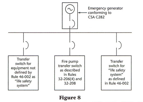
This C282 requirement is also reflected in Figure 8 from page 475 of the CE Code Appendix B Note on Rule 46-108(5) shown below:
Figure 8 in Appendix B Note on Rule 46-108(5) of the CE Code indicates that the main disconnecting means/overcurrent protection for the emergency power supply is, in fact, provided with the emergency generator in conformance with the CSA standard C282.
This figure also demonstrates that all aspects of design, installation and inspection of the disconnecting means/overcurrent devices located downstream from the generator main disconnecting means/overcurrent device, are subject to the compliance with the CE Code. The CE Code also specifically mandates a selective coordination between these overcurrent devices in the emergency distribution with the upstream emergency power supply overcurrent device.
Rule 46-208(1) of the CE Code places the following criteria for such selective coordination:
“46-208 Overcurrent protection
(1) The overcurrent device for an emergency power supply shall be coordinated with the overcurrent devices of feeders and branch circuits supplying life safety systems and other electrical equipment connected to the emergency power supply in order to provide selective operation of the branch circuit overcurrent device when a fault occurs in that branch circuit”.
Clause 8.7.2 also articulates a need for e selective coordination between the generator main overcurrent device and downstream overcurrent devices installed in emergency distribution feeders as follows:
“8.7.2 The overcurrent devices in the emergency distribution system shall be coordinated with the overcurrent device described in Clause 8.7.1 to maximize the selective tripping of the overcurrent devices described in Rule 46-208 of the Canadian Electrical Code, Part I when a short-circuit occurs. At a minimum, sufficient selective tripping shall be provided to ensure that a fault in any circuit directly downstream of an automatic transfer switch operates its respective overcurrent device while power is maintained to the other emergency circuits. Short-circuit currents of sufficient magnitude shall be made available from the generator to satisfy this coordination requirement”.
It should be noted that Clause 8.7.1 of C282 (see above) specifically allows certain components of the emergency power supply system to be connected directly to the generator terminals (upstream of the generator main circuit breaker). This relaxation was in general intended for connection of the fire pump feeder, in order to be consistent with the similar provision of the NFPA 20, as it is extremely difficult to accomplish such selective coordination between the main generator circuit breaker (provided by the generator supplier) and the circuit breaker of the fire pump feeder when this fire pump circuit breaker is installed in the emergency distribution on the load side of the generator circuit breaker.
However, compliance with Clause 8.7.1 of C282 and with Rule 46-208(1) of the CE Code does not appear to be applied consistently by the designers, installers and regulators.
Many electrical engineers (who are concerned about difficulties with a required selective coordination between the circuit breakers in an emergency distribution system) indicate in their design a direct connection of all emergency distribution feeders to a generator terminal box.
These engineers specify in their design that generator suppliers must provide not a single main generator overcurrent device, but a number of such devices (one – for each emergency distribution feeder) connected directly to a generator.
Their argument is based on an interpretation of the requirements of Clause 8.7.1 of C282 for each emergency generator to “be provided with a single lockable overcurrent device to connect it to the remainder of the emergency electrical power supply system“. They are in the opinion that a requirement for “a single overcurrent device” is met when such “a single overcurrent device” is designed for installation in each emergency distribution feeder connected to a generator.
These design engineers make an argument that Clause 5.5.1 of C282 (which lists all components of the emergency power supply system (see below), does not include the single overcurrent device in this list of the components of the emergency power supply system:
“ 5. 5.1 The emergency electrical power supply system shall consist of all of the equipment and systems necessary to supply reliable electrical power, including the following:
a) the engine generator set, which can include an auxiliary supply tank;
b) the fuel supply system, including tanks and piping as described in Clause 7.3;
c) automatic transfer switches and all associated wiring;
d) the emergency generator ventilation and cooling system;
e) wiring and all electrical components between an emergency generator and the emergency supply terminals of transfer switches specified in Clause 9; and
f) the exhaust silencer and piping to outdoors“.
Of course, such design approach creates inconsistency and confusion among the generator suppliers, and a request for interpretation of Clause 8.7.1 and the applicable revisions to the standard have already been submitted to the Technical Committee responsible for the development of C282.
Hopefully, the new edition of C282 will be amended to provide necessary clarification on this subject.
Meanwhile, as usual, an AHJ responsible for regulatory enforcement of C282 should be consulted for each electrical design and installation of an emergency distribution system.