There are other factors that complicate the situation. Some components are UL Recognized Components while others are UL Listed. UL recognized components are suitable for use only in an overall listed end use product. These recognized components are not suitable for use as field-installed units. Other products may carry a CSA Certification which may differ in some cases from a UL Listing. CSA and UL are both standards writing bodies. Verify the components that are allowable in your jurisdiction to be sure they are suitable for the intended use and acceptable to the AHJ. The rules here are not clearly black and white. There are some gray areas that require investigation.
Electrode Receptacle Terminology
There are housings, P-K housings, housings sold under the P-K name, which are standard #100, #200 and #300 borosilicate receptacle housings. There are electrode enclosures G Cups, GG Cups, G-2s, D-2s, 2UPs (a D-2 like housing) and myriad of boots, cups, and caps, which are referred to by the Code as electrode enclosures.
A commonly used term for the non-glass and ceramic electrode enclosures referred to as boots, cups and caps is “rubber-like.” Some prefer “polymeric” instead of rubber-like. Webster defines “polymeric” as “of or relating to a polymer.” The definition of “polymer” is “a naturally occurring or synthetic substance consisting of giant molecules formed from polymerization.” Rubber-like tells a better story.
Most rubber used today is synthetic. Most everyone understands rubber-like to indicate a flexible and pliable material. That’s the type material (a flexible and pliable material) referred to in this story.
Article 600—Electric Signs and Outline Lighting of the National Electrical Code underwent major changes in 1996. The most significant involved field installed outline lighting (commonly called border tubing). The requirements for border tubing fall under Part B of Article 600 (Field-Installed Skeleton Tubing). Misapplication of the requirements of Part B has caused numerous problems with border tubing, including fires caused by poorly installed neon, and the use of combustible electrode enclosures. Many of these rubber-like boots, cups, and caps were not UL Listed or Recognized.
The earliest edition of the Underwriters Laboratories Standard for Electric Signs that can be referenced for the story is March 1930.
The following was part of the UL Requirement before 1930, the exact date is uncertain:
Electrode Receptacles—129.It is strongly recommended that electrode receptacles be used.
130. Electrode receptacles for gas tubes shall, if used, be of a noncombustible, nonabsorptive insulating material.
131. Fiber, rubber, hot moulded shellac, or phenolic compositions are not considered suitable materials for electrode receptacles for ounting of high potential parts.
132. A rubber gasket may be used in connection with the mounting of an electrode receptacle.
133. A rubber gasket may be used around a gas tube in an electrode holder to prevent the entrance of dust, moisture, etc., provided the gasket is not depended upon for the insulation of the tubing and is not in contact with grounded metal such as the sign face.
134. An electrode receptacle shall not permit water to accumulate therein and thereby form a conducting path to grounded metal such as the sign face.
135. Each electrode receptacle shall be of substantial construction and shall provide means for reliability securing it to the sign face. Electrode receptacles shall not be secured to sign faces by means of sheet metal screws.
136. Each electrode receptacle shall be constructed so that, when installed, the spacing mentioned elsewhere in these requirements will be maintained.
This may seem like ancient history to some, but if every sign and neon installer followed these eight basic rules for neon installations, the amount of fires would be minimized and the reliability of the average neon system would be greatly improved. The removal from the 1999 NEC of “Electrode receptacles for the tubing shall be of noncombustible, nonabsorbent insulating material” for wet location situations, created a whole new set of problems.
Now back to the main subject at hand. There are a dozen varieties of glass electrode receptacles and enclosures available. Most of these are available from more than one manufacturer, and the others are available through at least three master distributors, and dozens of sign supply distributors.
The glass electrode receptacles (#100, #200 and #300 housings) are generic and are available from at least three manufacturers. The rubber-like electrode enclosures, polymeric boots, cups, and caps are not so generic. They are all different in configuration to some extent. They have different conditions of acceptability, and the conditions are not readily available in the exact form stated in the listing and/or recognition.
There are presently no polymeric or plastic boots, cups or caps to cover an electrode, straight or double-back that are UL Listed for wet locations. Be sure to note, this is UL Listed and, as indicated earlier, some of these products have CSA Component Acceptance for certain uses in wet locations. The conditions of acceptability with the CSA Component Acceptance are not absolute, so each product should be verified for specific uses with CSA. Contact CSA directly. As always, acceptability to the AHJ should also be verified. If in doubt, contact the local inspector or authority having jurisdiction and communicate.
CSA Component Acceptance Information
The old CSA Component Acceptance Mark is a CA connected like script. From Appendix E—CSA Marks, E.3: “The ‘old’ Component Acceptance Mark which indicates that a component has been accepted by CSA International on the condition that the use in an end-product is subject to further investigation.
“The mark is being phased out and replaced by the Component Marking, item E.9.15.”
The new mark is the standard CSA circular mark with an equilateral triangle at the lower right. From Appendix E—CSA Marks, E.15: “Component Acceptance Marking, intended primarily for factory-installed components, indicates that a component has been evaluated and accepted for specific applications and/or requirements, as stated in the accompanying literature.
In the early days, many housings were made of porcelain glazed ceramic. (See Photo 1.)
Photo 2 shows the manufacturer (KOLUX), Model No. 112, manufactured in U.S.A. and the voltage rating of 7500V. TRANSCO now has a porcelain glazed ceramic insert for the “P-K Type” Metal Clad Housing.
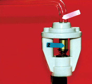
Photo 3 is another unusual housing made from borosilicate glass. The brass honeycomb component at the bottom of the housing is the contact for the electrode. The honeycomb replaces the spring contact in the #100, 200, and 300 styles. The electrodes used with this system had the equivalent of a nail about 1/2-inch long sticking out the end of the electrode where the wire is on current electrodes. This nail established the contact with the honeycomb brass device. The high-voltage power was connected to the wire projecting from the right side of the housing. This was covered by a separate piece of heat resistant glass (not shown) to insulate the connection from objects near the terminal point. The housing was held in place with a friction fit metal ring in most cases.
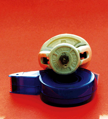
Photo 2. The manufacturer (KOLUX), Model No. 112, manufactured in U.S.A. and the voltage rating of 7500V.
Photo 4 is looking directly into the housing from the top. The honeycomb brass contact, and the nail in the electrode, provided a foolproof method of connection. You can see the electrode at the left of Photo 5. This housing and electrode are from the mid to late 1920s.
You have all heard of Pyrex glass. All Pyrex is borosilicate, but not all borosilicate is Pyrex. One blend of Pyrex, No. 7740 has a softening temperature of 820º C, while common borosilicate has a softening temperature of only 593ºC.
This of course is compared to most of the rubber-like materials, which are rated at a maximum of 105º C. The borosilicate will not burn, and the polymeric materials do melt and/or burn.
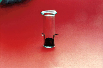
Photo 3. Another unusual housing made from borosilicate glass.
There is another major factor in the rubber-like electrode enclosures vs. glass electrode receptacle debate. All glass housings, including all the G Cup series must be securely attached to the background (sign or building) to meet UL Requirements. None of the rubber-like boots and cups presently has to meet this same requirement. This attachment to the background is critical to both safety and reliability.
All of the glass electrode enclosures are UL Listed for dry, damp and wet locations, except for the casino bushing, and it is UL Recognized. D-2 housings are not UL Listed for wet locations either. The 2UP is the only “D-2 Type” which is UL Listed for wet locations.
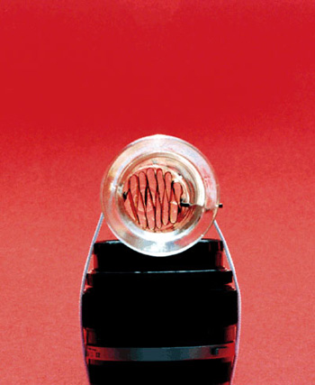
Photo 4. Looking directly into the housing from the top. The honeycomb brass contact, and the nail in the electrode, provided a foolproof method of connection.
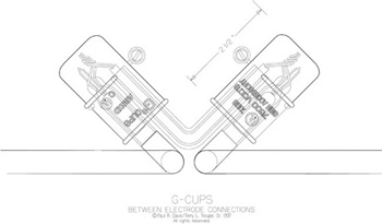
The G Cup is the only UL Listed housing for double backs which has a wet location listing when installed with proper orientation. See Drawing – 19R and Drawing – 23a to see how they must be installed to meet the conditions of the listing. The GG Cup shown in Drawing – 50 is also the only receptacle available for this type installation which is UL Listed for wet location. The 45º angular positioning on both of these devices is part of the listing requirement.
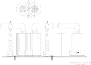
The G-2 Cup in Drawing – 47 is to be used in a channel letter with a housing type transformer. This is required in 600-23(b)(2). Field wiring as required for boots and caps is not allowed with housing type transformers. A D-2 [see Drawing – 52] or the 2UP [Drawing – 52(b)] can also be used for this.
The glass housings are numbered as follows, and you will find drawings of each in this story.
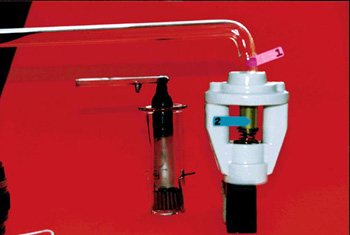
Photo 5. You can see the electrode at the left of Photo 5. This housing and electrode are from the mid to late 1920s.
The most common housings, prior to the advent of the rubber-like products, were the #100, #200 and #300 borosilicate housings. In the early days, they were all Pyrex.
The #100 is the largest diameter [Drawing – 55 (d)] and requires a panel opening of 1-3/4 inches. The #100 has a spring contact to connect the electrode to the secondary wiring system. This housing, allows water to wash the bugs and dirt out of the housing, the best of all the glass panel mounted housings except for the #300.
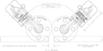
Drawing 19R. The G Cup is the only UL Listed housing for double backs which has a wet location listing when installed with proper orientation. See Drawing 19R and Drawing 23a to see how they must be installed to meet the conditions of the listing.
The #200 housing comes in two lengths. It is identical in basic configuration to the #100, but is smaller in diameter, and requires only a 1 5/16-inch panel opening. The #200P is 3.125-inches in overall, compared to 4.563-inches for the #200. The length is the only difference between the #200 and #200P.
The casino bushing (Drawing – 54) is the smallest glass housing available and, as pointed out earlier, is UL Recognized, not UL Listed. The panel opening is only 1-inch in diameter. The electrode connection to the secondary is made with a twisted wire connection, or better yet the connection can be made with a open end crimped type splice cap. This type of crimped connection is much more reliable than a twisted wire connection.
Drawing 23a. The G Cup is the only UL Listed housing for double backs which has a wet location listing when installed with proper orientation. See Drawing 19R and Drawing 23a to see how they must be installed to meet the conditions of the listing
The #300 and #300P probably cause the least problems of all the housings from #100 to #300 series of glass housings. They are open back as you can see in Drawing – 55(b). The #300 makes the secondary connection with a spring contact, and the #300P uses a spring clip. The positive connection of the spring clip to the electrode wire is by far the best way to go. With this method there is no room for error. It’s connected securely and misalignment doesn’t matter. With spring connections, misalignment is always possible, and can cause problems.
Drawing 50. The GG Cup shown in Drawing 50 is also the only receptacle available for this type installation which is UL Listed for wet location. The 45º angular positioning on both of these devices is part of the listing requirement.
Using electrode caps is a good approach. This provides a much larger surface area for contact between the spring and the electrode. The electrode button can easily slip by the spring, and cause an arc. The arc is contained in the glass housing, and rarely, if ever, will cause a major problem like a fire but, simply put, the electrode button is just not as reliable as the electrode cap. (Arrow 2 points to the electrode cap on the neon tube in photos 1 and 5.)
Last, but not least, is the P-K Type metal clad housing [Drawing – 55(c)]. This is probably the most maligned electrode receptacle in the neon industry. It has been wrongly blamed for more problems associated with neon installations. The improper installation and connection of the device is, and has always been, one of the major problems.
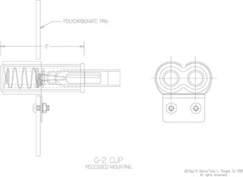
Drawing 47. The G-2 Cup in Drawing 47 is to be used in a channel letter with a housing type transformer. This is required in 600-23(b)(2). Field wiring as required for boots and caps is not allowed with housing type transformers.
Here’s a little bit of history about the P-K. The original patent application was filed March 12, 1947. Patent 2,488,065 was issued to C. M. Peterson on November 15, 1949.
From the Patent: “The invention relates to high tension terminal housings and has particular reference to insulator thereof.
“The principal object of this invention is to produce a housing and an insulator for high tension use, which will prevent the corona effect between the high tension cable and its conduit at a point adjacent the terminal.
“A further object is to produce a device which may be used with ordinary equipment now in use without materially altering its construction.
“A still further object is to produce a device which is economical to manufacture, easy to use and one which complies with all standard insulating requirements.”
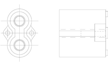
Drawing 52. This is required in 600-23(b)(2). Field wiring as required for boots and caps is not allowed with housing type transformers. A D-2 [see Drawing 52
One improvement on the original patent was the introduction of a metal clad housing with a one-piece flange to fasten the shell to the channel building, letter body, or sign cabinet. This provides a positive bonding connection between the shell and the letter or cabinet. The flange will also hold the housing tightly to the building. Other metal clad housings have a two-piece flange device which clamps around the basic metal shell of the housing, but are somewhat more difficult to install.
There are many opinions about what’s best when it comes to neon installations, and especially neon receptacles. The facts outlined here are based on field experience with the various components. Safety and reliability should always be priority one even though, today, too many times it is not a priority.
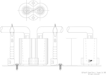
Drawing 52(b). This is required in 600-23(b)(2). Field wiring as required for boots and caps is not allowed with housing type transformers. A D-2 [see Drawing 52
The lack of proper bonding and grounding of the high-voltage part of a neon system, is most often the primary cause of poor reliability and fires. If all metal conduit is used, the bond is hard to lose. When PVC and other nonmetallic materials are used in the conduit system, it’s necessary to run a separate bonding conductor. This part of the equation becomes very difficult, especially with the changes to the Code in 1999.
The 1999 NEC added the following requirement for nonmetallic conduit.
“600-7. Grounding. Signs and metal equipment of outline lighting systems shall be grounded. Listed flexible metal conduit or listed liquidtight flexible metal conduit that encloses the secondary wiring of a transformer or power supply for use with electric discharge tubing shall be permitted as a bonding means in lengths not exceeding 100 ft (30.5 m). Small metal parts not exceeding 2 in. (50.8 mm) in any dimension, not likely to be energized, and spaced at least 3/4 in. (19 mm) from neon tubing shall not require bonding. Where listed nonmetallic conduit is used to enclose the secondary wiring of a transformer or power supply and a bonding conductor is required, the bonding conductor shall be installed separate and remote from the nonmetallic conduit and be spaced at least 1 1/2 in. (38 mm) from the conduit when the circuit is operated at 100 Hz or 1 3/4 in. (44.45 mm) when the circuit is operated at over 100 Hz. Bonding conductors shall be copper and not smaller than No. 14. Metal parts of a building shall not be permitted as a grounded or equipment grounding conductor.
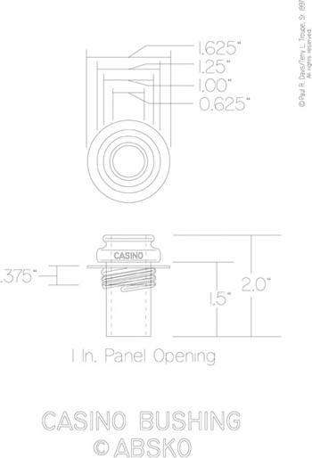
Drawing 54. The casino bushing (Drawing 54) is the smallest glass housing available and, as pointed out earlier, is UL Recognized, not UL Listed. The panel opening is only 1-inch in diameter.
“FPN: Refer to Section 600-32(j) for additional restrictions on length of high-voltage secondary conductors.”
Accomplishing the feat of stringing a bonding wire “1–1/2 in. (38 mm) from the conduit when the circuit is operated at 100 Hz or 1 3/4 in. (44.45 mm) when the circuit is operated at over 100 Hz” is not a simple operation. The bonding wire is exposed and susceptible to physical damage.
One other critical part of this situation here is the fact that the most important part of the high-voltage system (the bonding wire, the path to a safe ground.) is 1 1/2 to 1 3/4 -inches away from the components that can start the fires.
Neon systems are not all that difficult to install. Good planning and following the rules of the game are the two obvious keys to a safe and reliable installation.
Well made and correctly installed neon will last for 30,000 plus hours. It will be virtually free from fire hazards. If getting someone’s attention is important, brightly illuminated neon at night is one of the best answers.