The National Electrical Code published by the National Fire Protection Association covers numerous subjects relating to the installation of electrical systems including the installation of photovoltaic (PV) power systems. For practical reasons, even in this electronic age, the Code can only be so big and include so many details. In nearly every electrical installation, PV systems being no exception, there are areas where the code does not provide specific guidance. This article will discuss a number of those areas and perhaps a little light can be shed on questions that come from the field—both from PV installers and electrical inspectors about these particular areas. The following comments are based on field practice and a little common sense. In some cases, there will be objections to the material presented and also possibly some of the readers will have additional information that they would like to share. Please let me know what your areas of concern are and what other information you would like to share in relation to these particular areas. Also, if you have additional nooks and crannies that need some elaboration and exploration in this column, feel free to contact me.
The Safety Switch
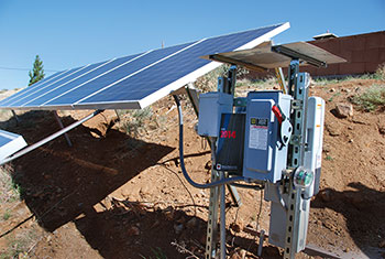
AC PV Circuits. PV systems will frequently require the installation of one or more disconnects, and those disconnecting means may, in many cases, be the so-called safety switch. See photo 1. A safety switch may be installed as the utility-required, visible disconnect, lockable-open AC PV disconnecting means between the AC PV output and the point of connection with the utility. These safety switches may be fused or unfused depending on the particular application. With ratings between 30 and 200 A or so, the safety switch will generally have an insulating, protective cover over the upper, line-side terminals as shown in photo one. The movable switch blades and the fuse holder contacts (if any) and the lower, load-side terminals are exposed and may be easily touched when the cover of the disconnect is open.
Generally, the safety switch has a safety interlock between the door or cover and the disconnect handle. The door is not easily opened when the disconnect is in the ON or energized position, but there is a mechanical override on this safety interlock.
In a non-PV application, where there is a utility source of power and a load, this disconnect will have the utility source attached to the line-side upper terminals and the load will be connected to the lower, load-side terminals. With the utility circuits connected to the line-side terminals, those connections are generally rendered partially inaccessible by the insulating protective cover. They can, of course, be accessed by a screwdriver or wrench, but the access holes are small and fingers cannot inadvertently reach the energized circuits being supplied by the utility. When the disconnect is turned to the OFF position and the door is opened, the moveable switch blades, the fuse holder contacts as well as the load-side terminals are now deenergized and safe to touch, which is a requirement for servicing the fuses.
Unfortunately, in PV installations, some PV installers and electricians become confused on the proper and safe method of connecting these switches. The thought process must be somewhat along the lines of the following: Power flows from the PV inverter to the utility, and so it must follow the normal power flow in a standard AC connected disconnect. As a source, the inverter output should be connected to the upper, line-side terminals and the utility should be connected to the lower, load-side terminals. This will allow the power to flow through the disconnect in this PV application in the same direction as it flows through the disconnect in a standard AC application.
Of course, with these connections, the normally safe load-side terminals, fuse contacts, and the movable switch blades are energized by the utility whenever the utility is present, and this is a particularly unsafe situation. Even with the safety switch turned OFF when the door is opened the potential for electric shock is very high.
So, from a common sense perspective, many PV installers use a rule of thumb when connecting these safety switches. That rule of thumb is that these switches should have the most dangerous circuit connected to the upper, line-side terminals where these more dangerous circuits can be somewhat protected from inadvertent contact by the protective insulated shield.
With this connection on the AC circuits of a PV system, the usually energized utility connections will be protected with the protective shield. The exposed switch blades and the fuse holder contacts (if any), and the load side terminals, which are now connected to the inverter output, will be relatively safe when the disconnect has been moved to the OFF position because the inverter output must go to zero within 32 milliseconds when the utility is removed from its output terminals. This is a UL Standard 1741 requirement related to the anti-islanding protection built into the inverter.
DC PV Circuits. When these safety switches are installed in the PV source and PV output circuits, a similar rule of thumb exists. Connect the upper line-side terminals of the safety switch to the most dangerous circuit, which, in this case, are the circuits from the PV array and the PV modules. These DC circuits are energized anytime there is light on the PV array. However, we must keep in mind that the load-side terminals will be connected to a utility interactive PV inverter DC input. These DC input terminals on the inverter may be energized for up to five minutes after the disconnect has been moved to the OFF position and has removed the energized PV circuits from connection to the inverter input. Energy storage capacitors inside the inverter may keep the inverter voltages on the DC input terminals high for up to five minutes and after that, they will be near zero. This is a requirement of UL Standard 1741. For this reason NEC Section 690.17(E) requires a warning label on these disconnects when used in the PV DC circuits warning that both the line and load side terminals may be energized after the disconnect has been opened.
WARNING
ELECTRIC SHOCK HAZARD
DO NOT TOUCH TERMINALS.
TERMINALS ON BOTH THE
LINE AND LOAD SIDES MAY
BE ENERGIZED IN THE
OPEN POSITION.
The Supply-Side Connection
NEC Section 705.12(A) allows supply-side connections for the PV inverter. Unfortunately, there are very few details about how this connection is actually to be made. Some of the PV inverters have a delta three-phase AC output that has no neutral. Others have a three-phase AC output with a neutral, but it is still a delta connection. The neutral is used for voltage measurements and the anti-islanding circuits but does not carry current. And, of course, we have the normal 240 V inverter outputs, some of which have a neutral and some that don’t.
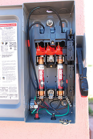
When a tap is made on the service-entrance conductors before the main disconnect, all of the phase conductors, the neutral and the equipment-grounding conductor should be tapped and routed to the new PV AC disconnect. In some cases, installers have not routed the neutral and/or the equipment-grounding conductor to the new PV disconnect. When the installer or electrician fails to route all of the circuit conductors together to the new disconnect, there is a potential for improper action of overcurrent devices under fault conditions. Also, as noted in Chapter 3 of the NEC, all of these circuit conductors should be in the same conduit or raceway. See photo 2.
While the NEC definitions do not allow these PV tap conductors to be called service-entrance conductors, these conductors from the tap to the first AC PV disconnect are subjected to the same fault currents that service-entrance conductors are exposed to. The 2014 NEC, in Section 705.31, requires that the first overcurrent protection on this circuit be within 3 m (10 feet) of the tap point or that cable limiters or current-limiting circuit breakers be installed within that distance. We will keep for another article, the discussion about the equivalency of cable limiters vs. current-limiting circuit breakers. Under this code requirement, the circuit from the added overcurrent devices to the PV AC disconnect can now be called a PV feeder. However, the circuit up to those added overcurrent devices required by 705.31 would still appear to require the same protection routing and conductor selection as service-entrance cables.
So, shedding a little light in this area—all conductors of the service entrance should be tapped and routed to the new AC PV service disconnect. Up to the first overcurrent devices, these conductors probably should be treated as service-entrance conductors in terms of routing and protection.
Older PV Arrays with New Inverters
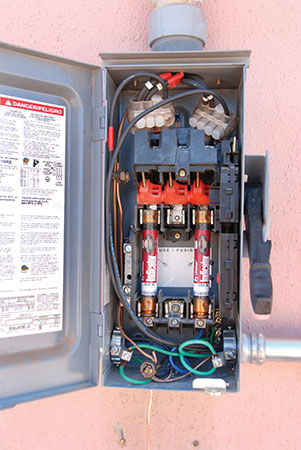
PV modules sold and installed in the United States more than five or six years ago most likely had USE-2 conductors attached and the exposed conductors in the array were wired with USE-2, which was perfectly fine for grounded PV arrays, even under the most recent NEC requirements. However, the older inverters (isolated or transformer type) may fail before the PV modules fail, and those inverters must be replaced. Ideally, the replacement inverter should also be designed to be used with grounded PV arrays so that the USE-2 module and array conductors still meet code requirements. Technology (and cost reductions) marches on and, unfortunately, it may not be possible to get a properly rated inverter that is suited for use with a grounded PV array. The replacement inverter that will accept the array voltage and current may be a transformerless (non-isolated) inverter that is designed to be used with ungrounded PV arrays that are wired with the newer PV cable or PV wire as required by 690.35. See photo 3.
Even if cost were not an issue, the certification/listing on the modules prohibits rewiring them with PV wire or PV cable, and the cost of removing the modules and rewiring the array would also be prohibitive. PV modules, with a life expectancy in excess of 40 to 50 years, should not be removed and discarded prematurely.
Although somewhat controversial, one potential solution is to continue to use the existing array wiring after carefully examining the PV modules, connectors, and all USE-2 conductors for any signs of deterioration. Any signs of deterioration would indicate that that part of the cable should be replaced, no matter what the cost. USE-2 cable is a very durable cable in the outdoor PV environment and has demonstrated lifetimes in excess of 35 years in the hot southwest environment. Any readily accessible exposed sections of the USE-2 conductors should be made not readily accessible by guarding. Where possible, exposed sections of USE-2 cable subjected to mechanical abuse or sunlight damage should be installed in a raceway for added protection and to meet the intent of 690.31(A). Of course, local codes and/or the AHJ may dictate how much of the PV array must be updated to the current code requirements when any equipment is updated or replaced.
Anyone think that we should enforce the letter of the Code and replace the entire PV array if a suitable inverter can not be found that can be used with the existing USE-2 conductors? Let me know.
Instruction Manuals and the UL Standards
Inspectors in various parts of the country who look closely at numerous PV installations and who are familiar with the requirements of the various UL standards that apply to PV equipment are finding, in some cases, that the installation instructions provided with a certified/listed product sometimes do not comply with the requirements of the standard. This may result in an installation that may not meet the requirements of the Code, may not meet the requirements in the standard, or may result in an unsafe installation.
The Standards Technical Panels (STP) who actually formulate the content of the standards are working to have the contents of the entire instruction manuals carefully reviewed by the Nationally Recognized Testing Laboratory (NRTL) responsible for certifying/listing the product to the standard. Eventually, this review will ensure that the instruction manuals are fully compliant with the requirements in the standard, which, in turn, dictates how the equipment is to be manufactured and installed. At some future point, it is hoped that tech notes and other material published by the manufacturers regarding the installation of a certified/listed product come under similar scrutiny.
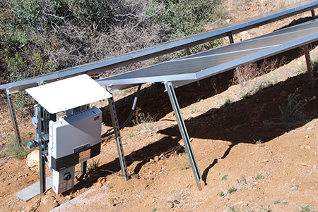
Module Mounting Systems and Racks
It should be noted that historically modules have shown mounting provisions using four bolts at the corners or possibly six bolts in total, and those mounting provisions can be used with any type of structure that the AHJ deems suitable. For example, on ground mount systems, racks made of heavy galvanized channels set in concrete in the ground have proven durable in numerous installations.
Most PV modules indicate one or more marked grounding points on the module frame. If an equipment-grounding conductor is properly connected to one of those grounding points on each module, no special provisions for grounding to the rack or other supporting structure are needed.
Both of these mounting and grounding systems may be time and equipment intensive, so the PV industry is developing many racking systems that will both mount and ground the PV module in one step.
Although, we have UL Standard 2703 that addresses racks and other module mounting systems, there is no requirement in the Code that the module mounting system be a certified/listed product. The standard primarily addresses the mechanical construction and integrity of the rack, the electrical continuity of the rack, and grounding provisions for the rack itself. Since the construction of PV modules varies greatly, at this time it is not possible to design, certify/list a racking system that can be used with all PV modules. PV module instruction manuals must show a mounting system and/or a grounding system that corresponds to the mounting (e.g., top clips) and grounding system (e.g., mounting clips that also ground the module to the rack) of a particular rack. In a similar manner, the rack instruction manual must indicate specific PV modules that have been evaluated for mounting and/or grounding with that rack.
Even when a certified/listed rack is used, the AHJ must verify that the connections to the supporting structure, such as roof trusses, are sufficient to distribute array weight, wind, and snow loading adequately.
Summary
Common sense and field practice that have withstood the test of user safety over time may fill in areas that the NEC does not clearly or specifically address. And as these areas become more commonly known and questioned, perhaps it is an indication that a code change is needed.
For More Information
The author has retired from the Southwest Technology Development Institute at New Mexico State University, but is devoting about 25% of his time to PV activities in order to keep involved in writing these “Perspectives on PV’ articles in the IAEI News and to stay active in the NEC and UL Standards development process. Seven to eight-hour presentations are still available on PV and the Code, and they cover 2008–2014 NEC requirements. He can be reached at: e-mail: jwiles@nmsu.edu, phone: 575-646-6105
The Southwest Technology Development Institute web site maintains a PV Systems Inspector/Installer Checklist and all copies of the previous “Perspectives on PV” articles for easy downloading. A color copy of the latest version (1.93) of the 150-page, Photovoltaic Power Systems and the 2005 National Electrical Code: Suggested Practices, written by the author, may be downloaded from this web site: http://www.nmsu.edu/~tdi/Photovoltaics/Codes-Stds/Codes-Stds.html.