Doesn’t everyone know everything about PV and the Code?
A new year is here and inspectors have time to ponder PV questions since few people are installing PV systems in the snow or are inspecting snow covered, outdoor installations. Photovoltaic (PV) power systems are evolving rapidly as changes are made in the Underwriters Laboratories (UL) standards governing those systems and in the Code requirements for installing those systems. And, of course, jurisdictions throughout the country adopt various editions of the code at different times. Hopefully, this series of articles will allow inspectors to keep abreast of the changing requirements for the installation and inspection of PV systems. However, questions come up when doing plan reviews or inspecting these systems and sometimes it’s difficult to get those questions answered. I receive several e-mails and telephone questions a week from AHJs throughout the country and in this article, I will address some of those questions that come in most frequently.
What about disconnects for AC PV Modules and Microinverters on the roof?
The necessity of having disconnects at the ac PV module or microinverter location or elsewhere on the roof in a PV system using such devices is a frequent question and is debated in a few jurisdictions. The following information should clarify the code requirements on this issue and offer some suggestions.
The 2011 National Electrical Code (NEC) in section 690.15 [also the same section in the 2014 NEC] requires that inverters (and that would include microinverters and ac PV modules) have disconnects from all sources of power (for maintenance) and that the disconnecting means shall be grouped at or within sight of the inverter. Of course, the dc conductors on an ac PV Module are exempt from any disconnect requirements as allowed by 690.6, but 690.6(C) does require an ac disconnect at the ac PV module location.
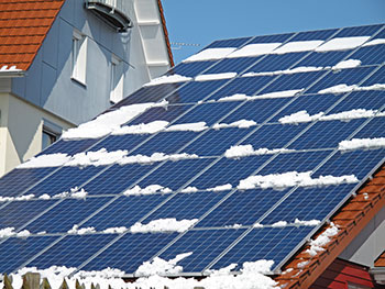
Microinverters and ac PV modules are typically located in PV arrays on the roof of a building, which is not considered a readily accessible location. NEC section 690.14(D) [690.15(A) in 2014 NEC] allows utility-interactive inverters not mounted in readily accessible locations to have ac and dc disconnects at the inverter location with an additional ac disconnect located according to the requirements of 690.14(C)(1) [690.13(A) in 2014 NEC]. This means that an additional ac disconnect must be located in a readily accessible area, normally at ground level. That additional disconnect may be a separate disconnect (such as the utility-required ac disconnect) or a backfed breaker in a load center provided the location requirements of 690.14(C)(1) [690.13(A) in 2014 NEC] are met. See photo 1.
An Exception to section 690.17 [Exception to 690.17(E) in 2014 NEC] permits connectors to be used as ac and/or dc disconnecting means provided they are listed and identified for the use and meet the requirements of section 690.33. That section requires that the connectors be load-break rated or require a tool to open in this not readily accessible location.
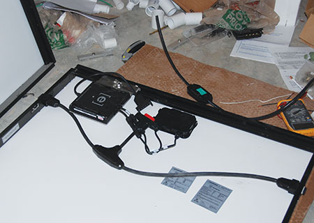
Some microinverter manufacturers and ac PV module manufacturers have had the nationally recognized testing laboratory (NRTL) that certifies/lists their products to UL Standard 1741 to also test and evaluate the ac and dc connectors on their products. The NRTL, in these cases, has certified that the connectors are suitable for the application and that they can be opened under load and therefore, meet the requirements of NEC section 690.33 where not installed in readily accessible areas. The instruction manuals for these listed products should state that the connectors on the products are certified by the NRTL as being load-break rated in the microinverter or ac PV module application and that additional disconnects for the microinverters or ac PV modules are not required on the roof. NEC section 110.3(B) requires that instructions provided with a listed product be followed.
It therefore appears through a combination of NEC requirements and NRTL certifications that the ac and dc connectors on some microinverters and ac PV modules are sufficient to allow safe operation and servicing of the system without the need for additional ac or dc disconnects on the roof.
Even given the facts above, PV installers should always exercise conservative, safe installation and maintenance practices. AC disconnects at ground level should be opened before using the microinverter or ac PV module connectors to connect or disconnect those devices for installation or replacement. This will reduce the current and voltage at the microinverter and ac PV module ac connector to zero. It will also reduce the current on the microinverter dc connector to very near zero. Although not the safest practice, if replacement is determined to be necessary on a single microinverter while on the roof and it is impractical to open the ground-level ac disconnect and ensure it stays open, the ac connector should be disconnected first and reconnected last.
Inspectors, as authorities having jurisdiction (AHJs), have the final say of what is and what is not required on any particular electrical installation (NEC 90.4). If a particular electrical inspector requires an ac disconnect on the roof, consideration should be given to the following. Outdoor-rated, unfused, 240-volt, 60-amp, 2-pole, pullout air-conditioning disconnects that cost less than $10.00 are available from several manufacturers. This disconnect could be easily located on the roof where the microinverter or ac PV module trunk cable terminates and the building wire cable begins, which is subsequently routed to the second ac disconnect at ground level. Such a disconnect is frequently cheaper and easier to install than a typical outdoor-rated, waterproof junction box.
How do we deal with Center-Fed Panels in 2014?
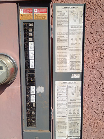
While the 2014 NEC in section 705.12(D)(2)(3)(d) allows center-fed panelboards to be used in load-side PV connections, engineering calculations are required. Many AHJs have questioned how can center-fed panelboards be accommodated without engineering calculations under the 2014 Code? See photo 2.
Certainly, the center-fed panelboard can be replaced in its entirety with an end-fed standard panelboard or load center.
In other cases, the center-fed panel may be one of those types that has interchangeable main circuit breakers. If a Chapter 2 load calculation on the building allows a lower main breaker rating and an interchangeable main breaker is available, then that reduced main breaker would allow a backfed PV breaker up to the difference between the busbar rating and the reduced main breaker rating.
Although not commonly done (because of equipment limitations and lack of breaker spaces), if the panelboard supports clamping devices for backfed breakers, a backfed main with a reduced rating might be installed if there is sufficient space for the added breaker. Of course, a Chapter 2 load analysis would have to be performed to determine if a reduced main breaker is possible at all.
These methods of addressing installations where the existing panel is a center-fed panelboard have been used with earlier editions of the Code in various jurisdictions, and they are still available to the installer and the inspector under the 2014 Code where engineering calculations are not available or are not cost effective.
As various jurisdictions adopt the 2014 NEC, AHJs are finding that installers are having difficulty locating equipment that meets the requirements of section 690.12 dealing with the rapid shutdown of PV systems on buildings. This article is being written in late October 2014 and at this time there is no Underwriters Laboratories (UL) standard addressing this requirement. Such a standard is under development by the Standards Technical Panel (STP) for UL Standard 1741, Inverters, Charge Controllers, Combiners and AC PV Modules, but a release date for even a draft standard is unknown and the draft may not be available until the early months of 2015. See photo 3.

Some jurisdictions are enforcing the requirement by requiring the use of field-assembled equipment that presumably meets the Code requirement even though such field-assembled equipment is not likely to meet the listing requirement of 690.12(5).
In order to avoid the complexity of high-current, high-voltage solid-state switching devices (which may be a common solution eventually), many designers and builders of field-assembled equipment are turning to power contactors. Unfortunately, the technical information provided with these devices does not, in many cases, address all the necessary information needed to select a power contactor that will operate in the PV environment. Many significant environmental factors must be addressed.
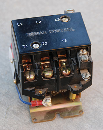
These environmental and operational factors include high operating temperatures, possibly approaching 75° to 85°C, cycle life in the thousands or tens of thousands of operations at full load (both voltage and current), the necessity to operate properly and extinguish arcs with direct currents flowing in both directions, the need to not interfere with existing inverter dc arc-fault circuit interrupter (DC AFCI) and ground-fault protection (DC GFP) circuits and numerous other items. These requirements and others for such a device would normally appear in the UL standard. Not having that standard and those additional detailed requirements indicate that many of the field-assembled rapid shutdown devices may not be durable, may not be safe, and may create more problems than they are intended to solve. See photo 4.
Some jurisdictions are requiring the installation of microinverters or ac PV modules or dc-to-dc converters that could presumably meet the requirement. Again, without a standard and without third-party nationally recognized testing laboratory (NRTL) evaluations of such devices, it is not clear that such devices will automatically meet the requirements for rapid shutdown of PV systems on buildings. As an example, without additional testing above the requirements of the existing UL Standard 1741 for inverters, it is not certain that an inverter, microinverter, or ac PV module ac output will be reduced to less than 30 V within 10 seconds when utility power is removed from that output. While all inverters certified/listed to UL 1741 for anti-islanding stop exporting power to the utility when utility power is removed from the output, the reduction of that output to 30 volts is not currently tested and verified. Additional requirements will be written into the standard to ensure that if the inverter is certified /listed as a Rapid Shutdown inverter, it will meet the 30 volt-10 second requirement for both the ac output terminals and the dc input terminals. And currently, the inverter dc input terminals are not required to be discharged to zero voltage in less than five minutes.
Because of the lack of a standard addressing the requirements of NEC 690.12, and the very low numbers of listed systems/equipment that may meet the NEC requirement without knowing the detailed requirements of a standard, several jurisdictions that have adopted the 2014 NEC are using the provisions of Section 90.4 to delay the enforcement 690.12. Typically, the jurisdiction is waiting until the standard is published and there are multiple manufacturers of equipment that have been certified/listed to meet the standard.
In the first months of 2015, when this article is published, it is anticipated that there will be multiple manufacturers of rapid shut down devices that have been certified/listed to meet the intent of the Code requirement and, possibly, also to the requirements of a draft UL standard should that standard be available. See the 690.12 Rapid Shutdown article by Bill Brooks and Jim Rogers in this issue for more details on the Code requirement and the details of implementation.
How Are Untapped Feeders Handled Differently in 2014?
Feeders between panelboards that may be subjected to currents from both the utility and currents from the output of utility interactive PV inverter are addressed in the load side connections section 705.12(D). In the 2011 NEC, conductors (feeders) and busbars were both addressed in section 705.12(D)(2) as modified by section 705.12(D)(7). With overcurrent devices at both ends, these untapped feeders were required to meet the 120% rule where the ampacity of the conductor could be no less than the sum of the overcurrent devices at each end divided by 1.2.
This particular requirement in the 2011 NEC (and in many previous editions of the Code) has never made sense from an engineering point of view. Normally, an existing feeder, before the addition of any PV system, has been sized to meet NEC requirements in Chapter 2 and Chapter 3 with an appropriately rated overcurrent device at the utility-sourced end of that feeder. A PV utility-interactive inverter is connected at the load end of the feeder with dedicated overcurrent device(s) that should be rated not more the rating of the existing breaker on the utility source end (to prevent tripping this breaker). In this configuration, where the feeder is sized at least as large as the largest overcurrent device at one end (normally the utility), it is not possible to overload this untapped feeder.
In the 2014 NEC, section 705.12 was substantially revised. Busbars and feeders were separated into different subsections. In the section on feeders [(705.12(D)(2)(1)], the only mention of conductors or feeders is a tapped connection where the inverter output is not made at the opposite end of the feeder from the utility source end. This tapped feeder is now subject to several very clearly written code requirements in the 2014 Code. For more details on the 2014 NEC 705.12(D) see the “Perspectives on PV” article in the January-February 2014 IAEI News.
The 2014 NEC, very deliberately, and wisely, left out specific references and requirements associated with untapped feeders having overcurrent protection on both ends from utility sources and the output PV utility interactive inverters. Now, we can use common sense and ensure that the feeder is sized properly to have an ampacity not less been the largest overcurrent device protecting the feeder. And, this will normally be the existing overcurrent device protecting the feeder from the utility-supplied currents. See photo 5.

For the increased clarity, the following proposal is being submitted for 705.12(D)(1) in the 2017 NEC:
“Where the inverter output connection is made to a feeder at the opposite end of the feeder from the primary source overcurrent device, the inverter output circuit overcurrent device shall not exceed the rating of the primary source overcurrent device, and the ampacity of the feeder shall not be less than the larger of the two overcurrent devices.”
Summary
Section 705.12(D) is an excellent example of how the code is evolving with greater clarity in each succeeding edition through the hard work of the code-making panels and the thousands of people who support them with well thought out proposals. As we look forward to spring, I encourage all AHJs and plan reviewers to submit additional questions via e-mail and phone.
For More Information
The author has retired from the Southwest Technology Development Institute at New Mexico State University, but is devoting about 25% of his time to PV activities in order to keep involved in writing these “Perspectives on PV” articles in the IAEI News and to stay active in the NEC and UL Standards development. Seven to eight hour presentations are still available on PV and the Code and they cover 2008–2014 NEC requirements. He can be reached at: e-mail: jwiles@nmsu.edu, phone: 575-646-6105
The Southwest Technology Development Institute web site maintains a PV Systems Inspector/Installer Checklist and all copies of the previous “Perspectives on PV” articles for easy downloading. A color copy of the latest version (1.93) of the 150-page, Photovoltaic Power Systems and the 2005 National Electrical Code: Suggested Practices, written by the author, may be downloaded from this web site: http://www.nmsu.edu/~tdi/Photovoltaics/Codes-Stds/Codes-Stds.html