Our increasing dependence on electricity in our technological society has made the reliability of electrical power a popular issue. Simply ask the hundreds of thousands of customers that were placed in the dark for days during the recent windstorms in California. Additionally, ice storms in the Northeast, tropical storms in the Southeast, blizzards in the Midwest, and potential terrorist attacks on the electrical system are all reasons utility electrical service may be less reliable in the future.
Rather than building a hardened electrical distribution system, a better compliment to the existing distribution system is to get electrical users to invest their own money on equipment that can provide electricity supply during system outages. Much attention has been focused on energy storage systems (ESS), Article 706 of the National Electrical Code (NEC) as the wave of the future. However, ESS has some real limitations. Without a supply of energy to replenish the battery, the benefit of an ESS can be limited in a prolonged outage. A combination of solar and storage and energy management of supply and loads are needed to make electricity supply reliable to the homeowner and business owner.
What are the driving forces for solar and storage?
The increasing costs of electricity, fear over the reliability of utility power, and environmental concerns are all reasons that electricity customers have invested in solar PV systems. As the costs of solar equipment have dramatically decreased in the past decade, many new markets have surfaced across the United States. As policy issues improve in various states and regions that reduce barriers to entry for these energy technologies, even more solar will spread into currently underserviced markets. For the most recent simplified permitting documents on solar PV systems, there are free resources by the U.S. Department of Energy at www.solsmart.org/permitting.
Some utility territories are still very resistant to the interconnection of solar to their system, so the combination of solar and storage can facilitate solar installations that do not export power to the utility distribution system. When Hawaiian utilities were struggling with the growing amount of solar on their systems, they placed a moratorium on solar systems exporting power to the grid. Because of the high cost of electricity in Hawaii, the storage industry volcano erupted overnight and a new island market was born. In a similar way, the multiple-day outages in California to prevent wildfires is currently birthing a much larger solar and storage market in California.
Outages and negative utility regulations are not new, but what is new are lower-cost solar and storage options. Simply adding solar and storage technologies in these markets is not sufficient, however. What made the storage market work in Hawaii was the addition of power control technologies to prevent exporting power to the utility grid. Rather than taking the residence off the grid, the Hawaii utilities allowed for solar to connect to the utility system as long as the system only exported very small amounts of power to the grid. These small export amounts allow for control systems to measure the power flows at the utility point of connection and place energy in an ESS, add or subtract load, or reduce output from the solar PV system. Power control systems (PCS) are now available on the market that can actively manage multiple power sources on the customer’s side of the utility meter.
What are Power Control Systems (PCS)?
A new term was added to the 2020 edition of the NEC in Section 705.13. Power control systems needed to be added to the 2020 NEC to accommodate the need for larger power sources installed at buildings. Rather than being limited by busbar calculations and service sizes, a power control system can actively supervise and manage multiple sources including the utility source. The utility source may be managed by dispatching energy from an ESS when the service is heavily loaded, or by using energy management systems (Article 750) to reduce controllable loads on the service. If the on-site generation is reaching the maximum allowed by the service conductors or the utility interconnection agreement, the PCS can reduce power production or store the excess power in an ESS.
Previous code editions had no practical way to account for the fact that solar PV and storage rarely provide power simultaneously. Since ESS is both a load and a source, in previous editions of the NEC, the ESS would negatively impact both the load and source side of calculations. The resulting requirements unnecessarily increase the size of building distribution equipment. With power control systems, the existing hardware can be used with controlled limits to prevent exceeding the ratings of the building’s electrical equipment.
How much can solar PV be safely connected to a home?
Until recently, the maximum amount of the solar photovoltaic (PV) power that could be connected to a residential service was limited by the size of the service itself [705.12(A), NEC-2017; 705.11(A), NEC-2020]. The new 2020 NEC in 705.11(A) now has the option to exceed the service size, where the sources are controlled by a power control system [705.13]. This means that a 100-amp service could have 200-amps worth of sources if they are controlled. The reason this is important is that several new energy storage technologies are designed to be connected in an ac coupled manner (through an ac circuit breaker) rather than by dc coupling.
Both types of ESS connections have benefits, and some building owners will end up with both types of systems for a variety of reasons. Before PCS were available, the provisions of 705.12 negatively impacted ac coupled systems since these systems add additional current to feeders, taps, and busbars with the existing calculations. Equally problematic is that utility interconnection rules may limit the amount of ac power an interconnection is permitted to install based on the assumption that all sources will export power to the utility grid when the grid is lightly load and cannot absorb the power.
In 705.11(A), the 2020 NEC limits the amount of on-site power source current to that of the service conductors. This is very similar language to that of 705.12(A) in the 2017 NEC except for the fact that it allows a significant exception to this basic rule by stating that systems installed according to 705.13 (PCS) are permitted to exceed the ratings of the service conductors. While at first, this may seem unnecessary or even dangerous, it is important to realize that even modest homes in the future may have 30-50 kW or inverters paralleled together to supply the loads of a dwelling. The author just purchased a new EV that includes a 150 kW, 3-phase motor drive (inverter) with a 64 kWh onboard storage system. If we can put all that in a car, don’t count out doing even a portion of that for the home.
Most Americans have been led to believe that a 100-amp service is small and that a 200-amp service is needed for the typical modern homes. Much of this perception comes from calculations required by Article 220 of the NEC to determine minimum service size. These calculations in Article 220 have served the electrical industry well for decades. However, the presupposition behind Article 220 is that none of our loads are controlled. Also, it includes assumptions such as lighting loads of 3 watts/ft2 which is often two or three times the value used in most homes today. Estimates about load diversity in a residential service are extremely conservative and often assume loads that are well above the actual loads in a home. Another way to talk about a 100-amp service is to call it a 19-kW constant power source (80 amps x 240 volts = 19,200 watts). This is a very different view of a utility service.
Is it possible for a house with a 100-amp service to be all-electric? Article 220 would allow homes up to around 2,000 square feet to be all-electric, depending on cooling and heating needs. However, the new definition of an “all-electric” lifestyle is that not only the home but the cars are also electric. According to Article 220, Branch-Circuit, Feeder, and Service Load Calculations, a home that is at the upper limits of a 100-amp service, is likely to require a 200-amp service should an electric vehicle (EV) charger be added to the home. This upgrade is needed even if the customer only charges their car at night when the rest of the house is at low load. That type of load diversity is not considered in the calculations of Article 220. Therefore, the addition of one EV, not to mention two EVs, may necessitate a service upgrade under the current rules.
Prior to the introduction of Article 625.41 to the Electric Vehicle Power Transfer Systems Article in the 2014 NEC edition, the only way to prevent the service upgrade with current rules was to severely limit the maximum charge current of the EV charger which is often not acceptable to the customer. In Article 625.42 (in the 2017 and 2020 NEC), the NEC allows for an automatic load management system to limit the current on the service equipment. This provision, specifically for electric vehicle charging, indicates that a system that monitors the service conductors and reduces the load of the electric vehicle charger would be permitted without having to perform new load calcs for Article 220. Incidentally, this provision in 625.42 was one of the original bases for the public inputs to the NEC for PCS.
Now enters 705.13, Power Control Systems. This enables the customer to augment their 19-kW constant power source (100-amp service) with as much solar and energy storage as they need to meet their energy needs. The power control system can be set so that no more than 80-amps is continuously drawn from the utility while meeting the home’s loads. If the EVs are incorporated into an energy management system [625.42] that interfaces with the power control system, then this combined system can limit the charging of EVs any time the service reaches the limits of its ratings. Additionally, the ESS can keep the EV charger at full power even when the utility service is at full power by dispatching energy from the ESS to the EV on an as-needed basis. This puts the viability of an “all-electric” home with a 100-amp service in a whole new light. Now a 100-amp service, with a 10 kW PV system and a 15 kW/20 kWh battery, can readily meet all the electrical demands of an all-electric house as long as all the uncontrolled loads and sources on the house meet Article 220. Think of what a 200-amp service could do…
What is the best way to make connections to a residential service?
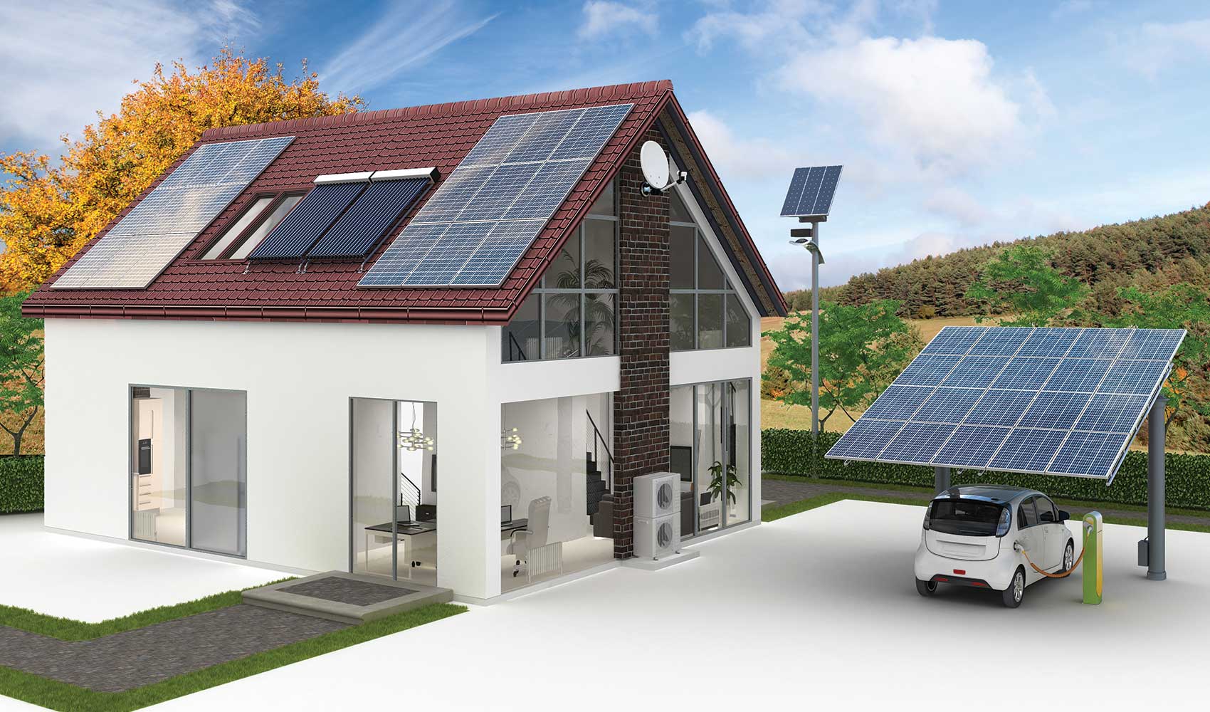
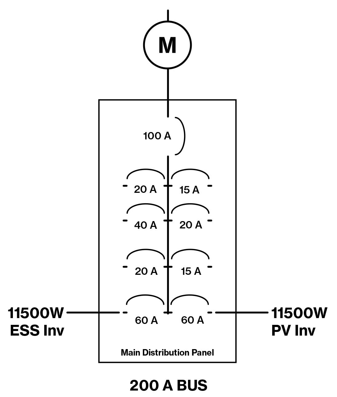
To discover better ways to make connections to residential services, it may be helpful to review the most common methods and why options are necessary. The first, most basic connection is to follow what has come to be known at the “120% rule.” As most who are reading this article already know, a 100-amp service with a 100-amp busbar in the main distribution panel is limited to the connection of a 20-amp PV breaker. The 2014 NEC refers to the maximum size of the power source based on 125 percent of the continuous output of the power source. A 3,840-watt, 240-volt inverter is capable of producing 16-amps continuously which is the maximum current for a standard 20-amp circuit breaker, as shown in figure 1. This provision was great when it was first introduced to the NEC in 1987 in 690-64(b)(2) Exception when a 4 kW PV system cost $100,000 in today’s money, but the times have changed.
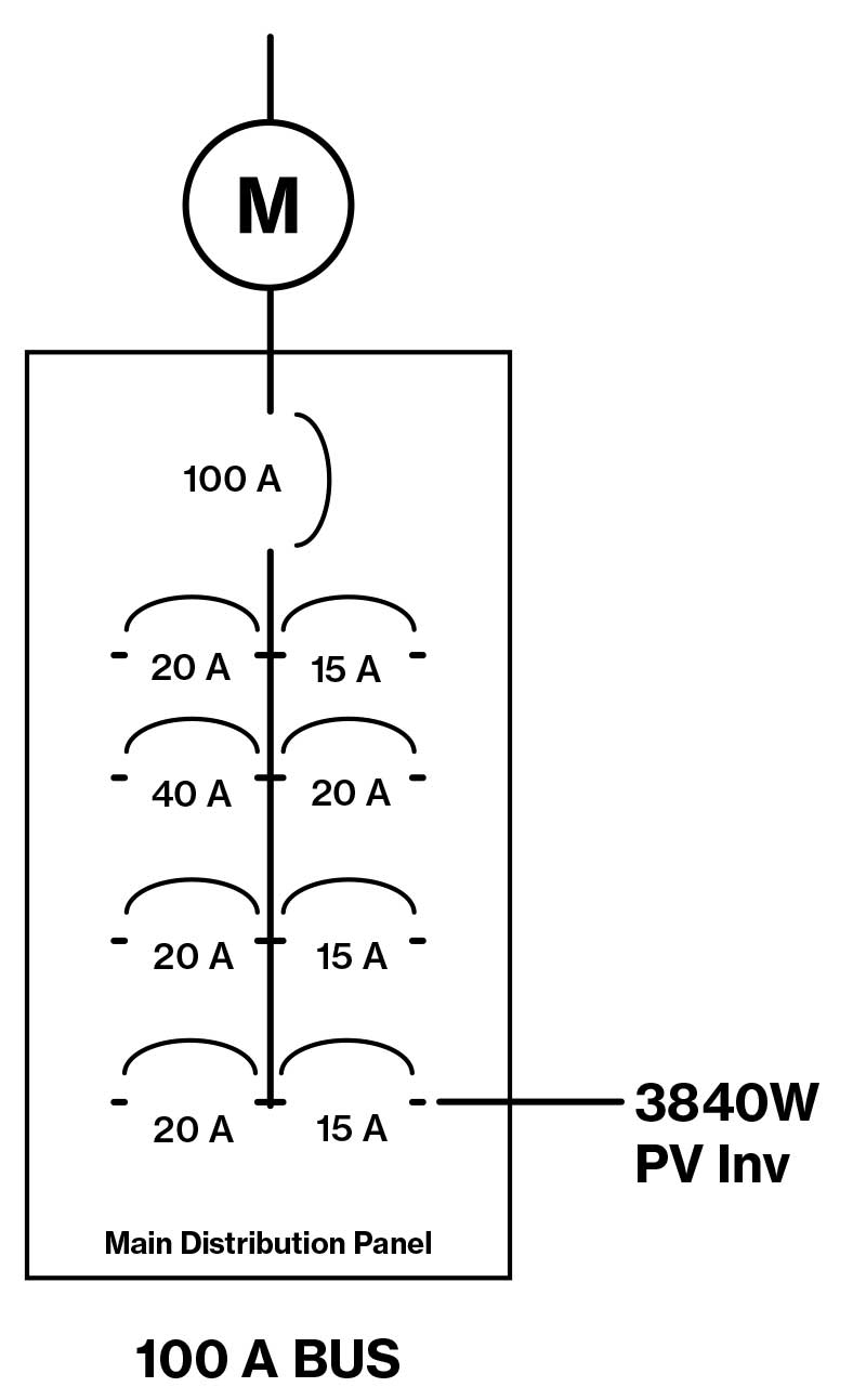
Since most customers want a larger PV system to reduce energy costs at their home, a common larger system to install is a 7.6 kW inverter on a 40-amp breaker (a common inverter size based on the largest PV system allowed on a 200-amp panel with the 120% option), a 9.6 kW inverter on a 50-amp breaker, or an 11.5 kW inverter on a 60-amp breaker. All three of these options are not permitted to be connected on the load side of the service disconnect shown in figure 1 since they cannot comply with 705.12 [705.12(B) in NEC-2017 and 705.12(D) in NEC-2014]. These larger systems are commonly connected on the supply-side of the service disconnecting means as permitted in 705.11 [705.12(A) in the 2017 and 2014 NEC].
There are many legal methods to make supply-side connections—and many more illegal methods. Examples of proper supply-side connections may include Renewable Meter Adapters (RMAs) approved by several utility companies, listed and properly rated connectors (as described in the PV System and “Utility Interconnects” by Jim Rogers in the January/February 2017 issue of IAEI Magazine), and multiple barrel lug kits listed for the specific distribution equipment. All of these methods require de-energizing the service conductors to perform the installation.
Many installers, when faced with installing an 11.5 kW PV system on a 100-amp service, will not hesitate to look to make the connection on the supply-side of the service disconnecting means as shown in figure 2. One of the most common concerns of installers and enforcement is how to properly wire these supply-side connections. While many of those questions are answered in the new section 705.11, Supply-Side Connections, in the 2020 NEC, have their drawbacks. The most significant drawback for backup power systems is that supply-side connections cannot assist in operating loads in a utility outage.
The Hawaiian Tie-In
A better alternative to supply-side connections was made available in the 2014 NEC and has become known as the “Hawaiian Tie-In.” The reason for the name is that many residential services in Hawaii are meter/main breaker combination panels which have no practical way to make a connection between the meter and the service disconnect. While many installers do make these connections, a field evaluation and label is necessary in many cases since the equipment often requires modification to make this connection. As long as the feeder and taps are properly protected in accordance with NEC-2020 705.12(B) [705.12(B)(2)(1) in NEC-2017, and 705.12(D)(2)(1) in NEC-2014], there is no problem with making a connection to the load-side feeder fed by the service disconnect.
Old-School is often too limiting for new PV+ESS+EV systems
For new PV systems in California or Hawaii, these systems require an energy storage system to make a large PV system financially viable. Once an ESS is added to a home, it is likely the customer will want to use the ESS for backup power during a utility outage. This necessitates that both the PV and the ESS be installed on the load side of the service disconnecting means making supply-side connections obsolete.
However, the “120% rule,” as it is referred to, may seem like an insurmountable obstacle to putting large amounts of PV and storage on a 100-amp service. This has caused many installers to change out the service equipment to install 200-amp rated equipment or larger with a 100-amp service disconnecting means.
The problem with this arrangement, shown in figure 4, is that the ESS can only be used to reduce site load during peak times, so backup loads cannot be operated similar to the problems with a supply-side connection. Systems providing power during utility outages will be discussed in the next section of the article.
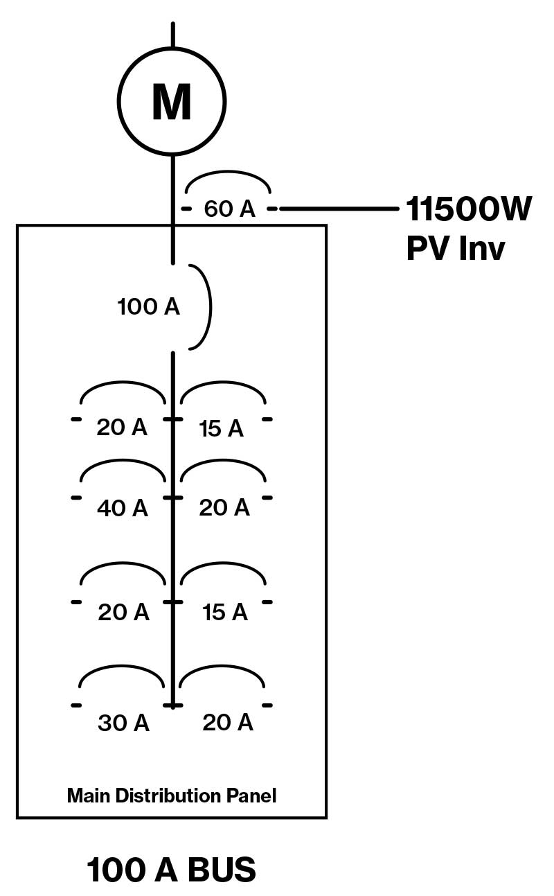
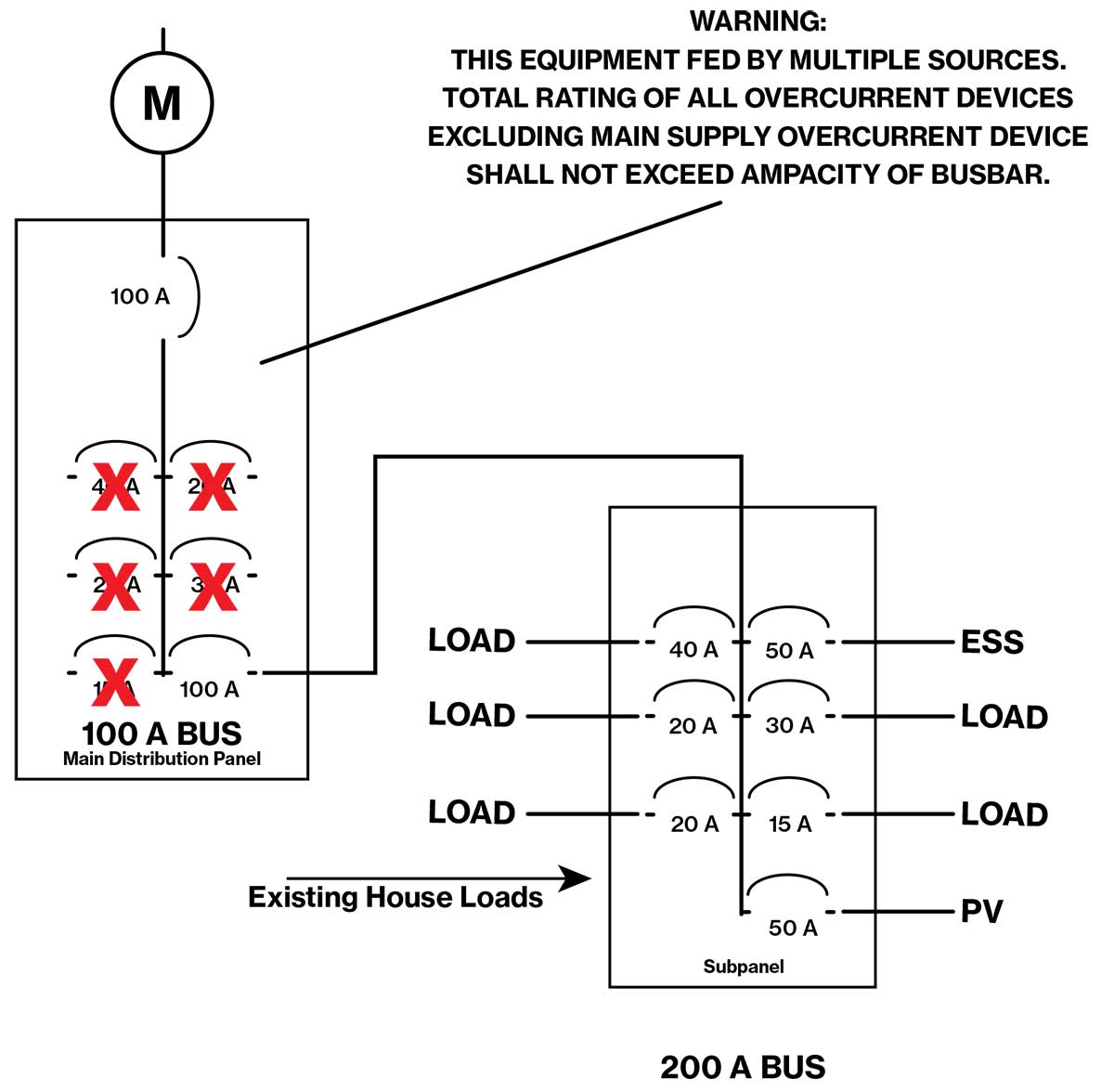
The 120% “rule” is actually only one of six options. Enter “option 3” to the mix in 705.12(B)(3)(3), which states that the busbar can be protected by limiting the sum of the breakers connected to the busbar, not counting the supply breaker from the utility. Assuming that a 100-amp service panel can accommodate a 100-amp feeder breaker, all the load breakers can be removed from the main panel and replaced with a single 100-amp breaker. All the load breakers can now be placed in another subpanel that has sufficient ratings to meet 705.12(B)(3)(1) or 705.12(B)(3)(2), as shown in figure 5.
What about emergency power for residences?
Really Old School
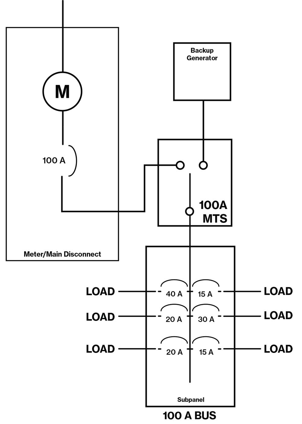
The most common method of connecting a generator to a house electrical system is to wire up a cord to a dryer outlet. This method is not supported in the NEC and is fraught with all sorts of safety hazards, such as energizing a plug with exposed metal and energizing downed power lines if the service disconnect is not turned off. We will focus our discussion on methods approved in the NEC. This brings us to Article 702, Optional Standby Systems. Article 702 covers systems, not legally required or for emergencies [Articles 700 and 701], powered by a generator through a manual or automatic transfer switch. Article 702 does not explicitly cover systems that run in parallel with the utility and then operate in what is not termed “island mode” in the 2020 NEC. These systems are covered in Article 705, Interconnected Power Sources, and Article 710, Stand-Alone Systems. A common method of generator connection is shown in Figure 6.
The key point in Figure 6 is that the generator is connected through a manual transfer switch (MTS). In 702.4(B)(1) it allows a generator sized for the load intended to be operated, rather than the full load of the facility. In other words, the owner manually turns off equipment that cannot be run on the generator before manually turning on the generator and then operating the transfer switch. If the owner miscalculates how much load can be operated, the generator bogs down or a breaker trips and safety is preserved (even though the power goes out again).
If the customer wants this operation to be automatic, 702.4(B)(2) requires that the generator be sized for the full load — 19.2 kW in this case — or that there be some sort of load control that limits the maximum load to that of the generator size. Several large equipment suppliers make products for this market.
The Y2K PV/ESS backup system
Some readers will remember a little event that occurred at the end of the last millennium that was termed Y2K. For those who cannot remember that time period, Google it. In California, thousands of PV/ESS systems were installed to prepare for the impending chaos. For most of these Y2K systems with PV, the systems did not employ transfer switches. Instead, the loads were split into two separate subpanels. One subpanel was reserved for loads that were not served by the home power system during a utility outage.
These loads might include the air conditioning compressor, electric stove, and electric dryer while remaining loads are run off of an on-site power system supplying the other subpanel. The technology used for these Y2K systems was not much different to what has been installed as PV/ESS systems in the past several years and required a multi-mode inverter connected to an ESS that had two distinct ac connections. One connection interfaced with the utility service and the other connection fed the loads to be operated during a power outage.
This other subpanel is where any on-site power sources or energy management system loads are operated. The feeder breaker from the utility is simply an additional power supply supplementing the on-site sources, like solar and ESS. In a utility outage, this second subpanel can be isolated from the utility service and then continue to power and manage the loads connected to this system as shown in figures 7 and 8.

The problem with this design is that the multi-modal inverter must be large enough to run the system. It also may be difficult with some equipment to upgrade or enlarge the system. Also, some multi-mode inverters did not have a means of running in combination with a generator, which may be necessary for a prolonged outage during a cloudy period. As seen in figure 8, some multi-mode inverters can be interfaced with other ac sources such as additional PV, wind, ESS, or a generator in what is termed an “ac-coupled” configuration as long as the multi-modal inverter has control over all the sources on its ac output.
The Wave of the Future (Now): Microgrid Interconnect Devices (MIDs)
A microgrid interconnect device (MID), as defined in 705.2, is a connection device, other than the multimode inverter, that separates the parallel sources and loads from the primary power source. When the MID disconnects the primary power source, the sources and loads are operating in “island mode,” and the rules of Articles 705 and 710 apply rather than Article 702. The size of the power source supplying the loads must be at least as large as the largest single load in the isolated microgrid [710.15(A)]. In other words, if the largest single load is a 30-amp water heater, the power source must be capable of operating that load.
There is an important distinction that must be understood related to the wording in 710.15(A). The NEC is not trying to size a power source for a stand-alone system. It is simply requiring that no single load can be connected to the system that the system cannot handle. If an installer were to size a system so that it was only sufficient to power that largest load, according to 710.15(A), it is unlikely that the overall power system will meet the homeowner’s expectations. However, when the system automatically shuts down because of insufficient supply for all the concurrent loads, there is no safety hazard. As long as no requirements from Articles 700 through 702 apply to this islanded system, the system meets the intent of 710.15(A). Also, keep in mind that the NEC is not “a design specification or instruction manual” [NEC 90.1(A)]; it is a safe installation requirement. As long as the system is electrically safe, whether it operates as expected during outages, is the concern of the owner and the installer, not enforcement.
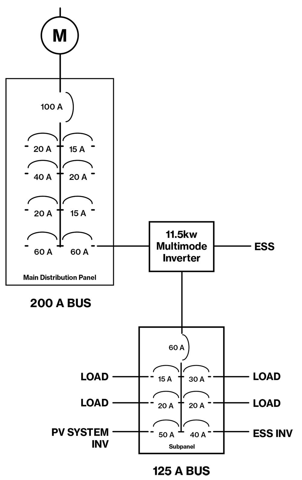
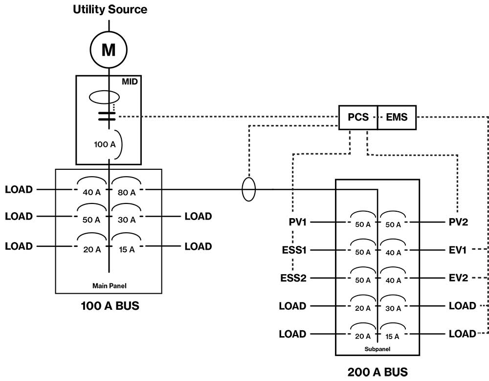
Many installers and enforcers get confused over the terminology that various manufacturers use to describe their equipment. Often the term “transfer switch” is used to describe some of the functions of an MID, so it is easy to see how enforcement may erroneously apply the sizing requirements of 702.4(B)(2) to a power system connected through a MID. While the 2020 NEC helps to differentiate between these two systems, more work may be needed in future Code editions to make this distinction clearer. Figures 9 and 10 show how a MID system could be installed on a typical 100-amp service.
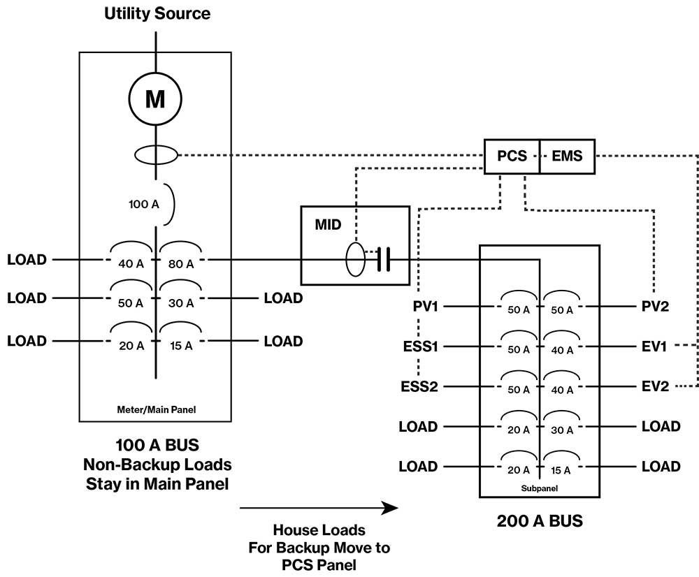
There is a lot included in figure 9. First of all, this system requires a power control system (PCS) since it has the physical capabilities of feeding much more than 16 amps back into the main panel. Also, there is a need for an energy management system (EMS) [Articles 625 and 750] as the loads could be far above the supply in the subpanel if these loads are not controlled. This second subpanel, with proper power and load management, may even be capable of charging multiple electric vehicles. Within the next few years, the vehicles themselves, through vehicle-to-grid (V2G), will also be able to effectively augment the supply of power with extra storage capacity if the customer wishes to use it. Widely available products to perform these functions are less than three-to-five years away and these functions are technically feasible today. Believe it or not, this is all now feasible with a mere 100-amp service.
Now that both a PCS and an EMS are involved, we can operate the loads in the subpanel without needing to upgrade the service or distribution equipment. We can feed more than 16 amps back into the main panel from the subpanel since we are monitoring all sources entering the main panel. This example illustrates the all-electric (cars included) house of tomorrow that is currently feasible today without the need for a service upgrade or the main panel changeout.
This is an exciting time for everyone in the electrical industry. Newly available equipment certified to this new PCS standard is already on the street which will make enforcement of load-side connections more feasible. The days are numbered where contractors will feel the need to make sketchy supply-side connections in service equipment without proper field certifications. Some in enforcement may be hesitant to approve this newly certified PCS equipment in their communities. However, with all these new smart power resources, strengthened by the new UL standard and key advances in the NEC, adoption and enforcement is more streamlined than it ever was for source interconnections. Even though PCS is new in the 2020 NEC, for those on earlier editions, one recommendation is to use the provisions in NEC 90.4. To help substantiate the use of PCS for those not on the 2020 NEC, there is a standard to which equipment can be certified, and there is specific installation language provided in NEC-2020 in 705.13.
Power systems for homes and businesses will become more reliable and complex as the need to maintain electrical power becomes more and more important in our technological society. The electrical infrastructure on both sides of the service disconnect can be augmented with smart power resources that insulate the customer from the inevitable interruptions in utility power. Manufacturers, listing agencies, and other industry stakeholders are working in harmony together to develop those cost-effective smart power solutions. Our communities, government, the NEC, and the serving utilities will all be working together to encourage customers to invest in the technologies they need to provide for reliable power. This type of cooperation will result in the most reliable electrical system at the lowest cost. The future is sunny with sides of storage and EVs.