Managing Electrical Risk
The use of electricity has inherent risks, particularly electric shock and arc flash hazard. However management tools and technology are readily available to mitigate and manage these risks.
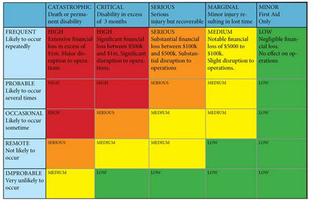
Figure 1. Risk Assessment Matrix
Hazards and risks are not the same thing. A hazard is something with the potential to cause harm and damages whether that be to equipment, processes or personnel. Risk is the likelihood that the event will occur and result in damages.
The relationship between hazard and risk can often be summarized via a Risk Assessment Matrix as per figure 1, which provides an easily understood, defined approach to hazard analysis and risk assessment.
Once the appropriate level has been determined then management action can be summarized using a simple response chart.
Category — Action
HIGH— Do not operate equipment or process until remedial action has been implemented.
SERIOUS— High priority, remedial action must be taken at the earliest opportunity.
MEDIUM —Take remedial action at the next convenient opportunity.
LOW— Risk level is acceptable, remedial action is discretionary.
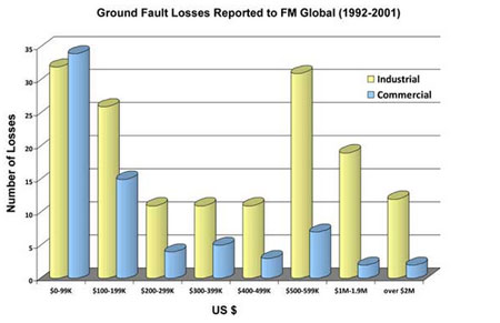
Figure 2. Published Losses
We know from experience and empirical data that over 85% and probably closer to 98% of all electrical faults are phase-to-ground faults and we have documented and quantitative data from various studies summarizing the costs and impact of ground faults on industry.
One leading US based insurance company notes that over a 7 year period their clients reported 228 losses that were attributed to ground faults resulting in payments of $180 million. There were 72 occurrences in the commercial sector, hotels, universities, hospitals and shopping malls at an average cost of $830,000 each and 156 occurrences in manufacturing locations with an average cost of $769,000 per occurrence.
With the information available we can categorize the Risk Assessment of an electrical ground fault to be somewhere between HIGH and SERIOUS with financial damages according to one insurance company averaging $769,000 the majority of which is likely to be the costs associated with business interruptions and capital equipment damage. We can define the frequency as Occasional and thankfully the impact on personnel to be low as most ground faults simply result in process outages.
At the other extreme is the electrical arc fault which has a lower occurrence rate than a ground fault but the potential damage is significantly higher. According to statistics compiled by CapSchell Inc, a Chicago-based research and consulting firm that specializes in preventing workplace injuries and deaths, there are five to ten arc-flash explosions that occur in electric equipment every day in USA, resulting in medical treatment. Arc flash victims may suffer from chronic pain and scarring. Workers may also have difficulty re-integrating into the community, and may experience anxiety, depression, or other psychological symptoms. The social and economic costs may also be high. Workers’ compensation pays only a portion of lost wages. Some workers may not be able to return to their pre-injury job. Employers bear the costs associated with lost productivity, reduced competitiveness, employee rehiring and retraining, as well being subject to increases in workers’ compensation premiums. Published data from Washington State notes that from September 2000 through December 2005, 350 Washington workers were hospitalized for serious burn injuries occurring at work. Of these, 30 (9%) were due to arc flash/blast explosions. Total Workers’ Compensation costs associated with these 30 claims exceeded $1.3 million, including reimbursement for almost 1,800 days of lost work time.
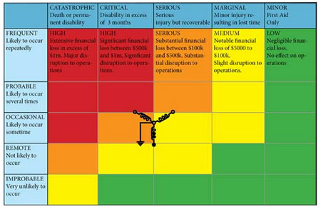
Figure 3. Risk Assessment Matrix – Solidly Grounded System
An arc flash is a breakdown of the air resulting in an arc which can occur where there is sufficient voltage in an electrical system and a path to ground, neutral, or another phase. An arc flash, with a high level of current, in the range of 1000 amps or more, can cause substantial damage, fire or injury. The massive energy released in an arcing fault can instantly vaporize metal in the path of the arc, blasting molten metal and expanding plasma outward with extreme force. The result of the violent event can cause fire, destruction of equipment and serious injury to personnel in the vicinity of the blast.
An arc flash would likely have a Risk Assessment of MEDIUM to SERIOUS due to its low frequency but devastating impact on equipment and personnel.
There was a recent electrical fire at a recreational facility that resulted in consequential damages of $400,000, mostly in business interruption costs and as the forensic engineers and insurance investigators conducted their review, the focus was who and what was to blame for the losses.
The engineers and insurance representatives for all parties reviewed all aspects of the electrical equipment that was specified and installed including settings and commissioning reports. They questioned the integrity of the electrical switchgear, the protection relays and components specified in the electrical system, the installation practices of the electrical contractor, the maintenance schedule and its effectiveness etc.
The focus was not on whether the electrical system specified or used was correct or safe but simply who in the supply chain of electrical equipment and services would pay the damages. During the course of the investigation a simple question was raised. Was the grounding method chosen by the consulting engineer and the facility owner or operator a contributing factor?
The most common grounding method in use in North America for both commercial and industrial facilities and the method chosen in this specific instance is called solidly grounding. However, this grounding method is known to have the highest incident level of arc flash events and electrical fires. There are estimated to be around 210,000 industrial facilities that operate solidly grounded despite the higher level of risk.
Simply be using the Risk Assessment Matrix, the consulting engineer or business operator could have readily identified that choosing to specify a solidly grounded electrical system while economical and simple to implement, the associated hazard frequency level of OCCASIONAL and a hazard severity level of SERIOUS would result in a MEDIUM level of risk and that remedial action would need to be taken at the next convenient opportunity.
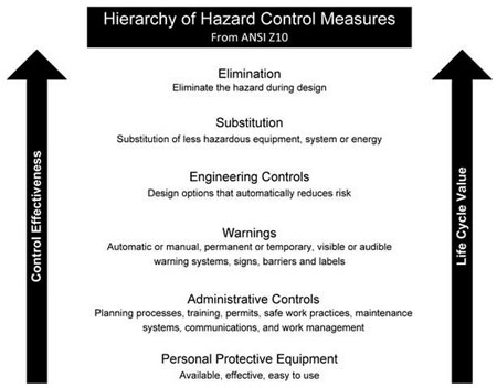
Figure 4. Hierarchy of Hazard Controls
In fact, since this was the design stage, preventative measure could have been implemented to ensure a REMOTE frequency and MARGINAL or MINOR impact to secure a LOW level of risk. Rather than point fingers post event looking to cast blame or recover damages, the responsible approach would be to proactively reduce the likelihood of the hazard and reduce the impact of the hazard at the design stage.
The least common method but safest grounding method in use today in North America is Resistance Grounding where a resistor is connected between the neutral of the transformer secondary and the earth ground. The reasons supporting this option for electrical grounding can be found in several IEEE (Institute of Electrical and Electronic Engineers) Reference Guides.
IEEE Standard 141-1993 Recommended Practice for Electric Power Distribution for Industrial Plants
7.2.2 There is no arc flash hazard, as there is with solidly grounded systems, since the fault current is limited to approximately 5A. Another benefit of high-resistance grounded systems is the limitation of ground fault current to prevent damage to equipment.
The investigation continues and no blame or fault has been established nor damages awarded but the possible implication for the consulting engineering fraternity could be substantial. If the insurance investigation determines that the root cause was the specifying of a solidly grounded system which by its very nature contains a risk of arc flash occurring, then the responsibility lies with the specifying engineer.
The question for engineers, business owners, safety managers etc is what steps to take next after defining and categorizing the Risk and Hazard.
The first choice is to Eliminate the hazard, this is the most effective control measure and must always be considered first. If the hazard cannot be eliminated completely then there are a number of control options that can be used to prevent or minimize exposure to the risk.
- Substituting the risk for a lesser one
- Redesigning the equipment
- Isolating the hazard
- Establish safe work practices
- Personal Protective Equipment.
So why then do we start electrical safety with a focus on protection rather than prevention? We quite readily invest in and offer safety awareness training, we purchase and post warning signs, we insist on safety goggles and gloves and perhaps even PPE (Personal Protective Equipment) but we do not invest in prevention and take the steps necessary to eliminate or reduce the likelihood of a hazardous electrical incident.
Administration and the use of personal protective equipment are the lowest priority on the list of controls and should never be relied on as a primary means of risk control. Personal Protective Equipment should be used as a last resort when exposure to risk is not or cannot be minimized by other measures.
Elimination of the Hazard
In practice, the majority of electrical faults experienced in industrial low-voltage systems are phase-to-ground faults. For solidly grounded wye systems, the IEEE Red Book (Std 141-1993, Section 7.2.4) states that “A safety hazard exists for solidly grounded systems from the severe flash, arc burning, and blast hazard from any phase-to-ground fault.” The same standard recommends a solution to resolve this issue. Section 7.2.2 of the IEEE Red Book states that when using high resistance grounding, “There is no arc flash hazard, as there is with solidly grounded systems, since the fault current is limited to approximately 5 A.” The Red Book is referring here to phase-to-ground faults.
High resistance grounding (HRG) of AC electrical systems allows continuation of power to the circuit while maintenance personnel isolate the faulted equipment. This permits avoidance of an unplanned shutdown of a continuous process facility.
High resistance grounding, as a technology, was originally applied to industrial power distribution systems in industries as diverse as: food processing, mining, petrochemical and even commercial installations such as airports, data centers, etc. The main driver was to enhance the reliability and availability of power distribution equipment and prevent unplanned outages. HRG has also proven to be very effective in significantly reducing the frequency and severity of arc-flash accidents by limiting ground fault currents during the first phase to ground fault conditions.
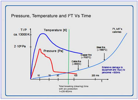
Figure 5. Arc Flash Characteristics
Industry data indicates that 85% to 98% of electrical faults start as phase-to-ground faults. Resistance grounding inserts impedance between the transformer neutral and ground and limits the ground fault current to less than 5 amperes. With the ground fault limited to a low value, there is insufficient fault energy for the arcing to take effect. The hazard frequency is reduced during the first phase to ground fault. The first phase to ground fault normally initiates an alarm to allow isolation of the faulted equipment or circuit before the fault can escalate to phase to phase to ground fault. In fact, the NFPA 70E -2009 Standard for Electrical Safety in the Workplace states in section 130.2 FPN No.3 “Proven designs such as arc-resistant switchgear,…high-resistance grounding and current limitation….are techniques available to reduce the hazard of the system”. OSHA subpart S issued on February 14 2007, and effective on August 13, 2007 is based on NFPA 70E.
Substitution of the Hazard
An arc is developed in milliseconds and leads to the discharge of enormous amounts of energy. The energy discharged in the arc is directly proportional to the square of the short circuit current and the time the arc takes to develop, i.e. energy = I2t
The damage resulting from the arc depends on the arcing current and time and of these two factors time is the most easily controlled and managed. Rules of thumb for different arc burning times are:
- 35 ms or less – no significant damage to persons or switchgear which can often be returned to use after checking for insulation resistance
- 100 ms – small damage to switchgear that requires cleaning and possibly some minor repair. Personnel are could be at risk of injuries.
- 500 ms – catastrophic damage to equipment and personnel are likely to suffering serious injuries.
The goal of arc mitigation technology is to protect personnel and property and to effectively accomplish this we must first detect the arc and then cut the flow of current to the arc in as short a time as possible. As noted above the target is to achieve a total reaction time of 100ms or less from detection of the arc to isolation of the circuit.
Current-limiting fuses are often used in the design of electrical distribution systems to protect electrical equipment under high available short-circuit conditions (NEC110.10). They are able to protect the equipment from the significant thermal damage and magnetic forces associated with high short-circuit currents by actually reducing the current that flows and the time that it flows. Within their current-limiting range, they keep the current from reaching its peak during the first ½ cycle. And because they can react so quickly, the current is driven to zero in as little as ¼ cycle, or even less.
This great reduction in damaging current and time not only protects equipment from significant short-circuit currents, but naturally also helps protect workers that might be exposed to horrendous arc-flash energies. The difference between a 30,000-ampere arcing fault that lasts for 30 cycles, and a let-through arcing current of 1,000 amperes that lasts for ¼ cycle can be the difference between a worker driving home after work and a ride to the morgue.
An arc is accompanied by radiation in the form of light, sound and heat. Therefore the presence of an arc can be detected by analyzing visible light, sound waves, and temperature change. To avoid erroneous trips it is normal to use a short-circuit current detector along with one of the aforementioned arc indicators and the most common pairing in North America is current and light.
The burning of the arc heats up the ambient air causing it to expand and create a measurable increase in pressure inside the switchgear. In Europe it has become common practice to use the combination of light and pressure as positive indicators of an arc. The pressure sensor has an operating time between 8ms and 18ms and when combined with a circuit breaker with an operating time between 35ms and 50ms we have achieved our goal of 100ms or less.
However, many older circuit breakers operate closer to 80ms and these require to be paired with a faster acting arc detection device. Arcs produce light at intensity levels that excess 20,000 lux. This can be detected through special optical sensors connected to a relay system that has a typical operating time under 1ms and is the fastest arc flash detection technology currently available. The operating time is independent of the fault current magnitude since any current detector elements are used only to supervise the optical system.
With optical arc protection technology installed the relay operating time is essentially negligible compared to the circuit breaker operating time and the cost is fairly low since current transformers are only needed on the main breakers. Again, if we sum up the circuit breaker operating time and the optical arc detection time we are well below the goal of 100ms regardless of the age and speed of the circuit breaker and have mitigated the damage to a more reasonable level.
Isolating the Hazard
Arc resistance switchgear is designed to contain the hazard and vent the destructive energy away from personnel. The remains damage to the capital equipment but less than in conventional switchgear, there remains process interruptions but perhaps less than in conventional switchgear but personnel are isolated from the hazard.
Remote racking and remote switching ensures that personnel are not in close proximity to electrical switchgear in the event of an arc flash incident. Neither affects the frequency or severity of the hazard and the consequential impact on equipment damage and process interruptions but both ensure a lower risk of injury to personnel.
If we deploy proven technology such as High Resistance Grounding to reduce the frequency of the ground fault and arc flash hazard to OCCASIONAL or REMOTE and we take steps to reduce the impact of the hazard through the use of current limiting fuses or fast action optical relays to MARGINAL or MINOR, if we isolate personnel from the Hazard through arc resistant switchgear or remote racking then we can achieve a LOW risk from Electrical Hazards. We have the technology and the management tools to make the difference between sending 5 to 10 persons per day to hospital due to arc flash explosions to 5 to 10 per month.
Let’s get serious about Electrical Safety.