
Selective coordination has been required for multiple elevators, supplied from a single feeder, since the 1993 National Electrical Code (NEC®). This requirement was based on a similar requirement in the Canadian Electrical Code. In the 2005 NEC, requirements for selective coordination were added to 700.27 for emergency (700.28 in 2014 NEC) and 701.18 for legally required standby systems (701.27 in the 2014 NEC). These requirements additionally applied to essential electrical systems in healthcare facilities, since these systems were required to follow the requirements of emergency systems. In addition, a definition of Coordination (Selective) was modified and moved from Article 240 to Article 100 to better define and emphasize the objective of this requirement. This definition was important to identify the “level” of coordination when compared to traditional “coordination and short-circuit studies”. The definition of selective coordination indicated localization of all overcurrent conditions. If one looks at the definition of overcurrent in Article 100, it indicates that this includes overloads, ground faults and short-circuits. Therefore, selective coordination is considered “total” coordination. Traditional coordination and short-circuit studies, did not necessarily assure “total” coordination, simply the recommended settings for the devices installed to achieve the best “level” of coordination possible with the installed overcurrent protective devices.
In subsequent editions of NEC, the requirements for selective coordination have been expanded to include Critical Operation Power Systems (COPS) in the 2008 NEC and Fire Pumps in Multibuilding Campus-Style Complexes in the 2011 NEC.
Over the years, the biggest challenge for the electrical inspector with regard to selective coordination was assuring code-compliant selectively coordinated systems were being installed. This was based on two concerns. First, was the definition of selective coordination properly interpreted as “total” coordination? Second, were the overcurrent protective devices properly selected, documented, and installed to meet the definition of selective coordination? This article will discuss changes that have occurred in the 2014 NEC to address these two concerns as well as examples of documentation that must be submitted to support compliance with selective coordination.
Definition of Selective Coordination
The first change in the 2014 NEC is to the definition of Coordination (Selective). This definition was revised to:
Coordination (Selective). Localization of an overcurrent condition to restrict outages to the circuit or equipment affected, accomplished by the
choiceselection and installation of overcurrent protective devices and their ratings or settings for the full range of available overcurrents, from overload to the maximum available fault current, and for the full range of overcurrent protective device opening times associated with those overcurrents.
These revisions clarified the intent of the definition. The first change was to replace “choice” with “selection and installation”. This helps clarify that it is not a “choice” but rather the proper “selection and installation” of overcurrent devices (types, ratings and settings) that achieves selective coordination. The additional text added to the end of the definition clarifies that the term selective coordination applies to the full range of overcurrents, from overload to the maximum available fault current and all operating times of overcurrent devices for these overcurrent conditions. This added language makes it clear that “partial or limited coordination,” such as coordination for operating times of 0.1 seconds or longer would not meet the definition of selective coordination.
Selective Coordination Documentation Requirements
A key concern for selective coordination is to provide proper documentation of compliance. The 2014 NEC has addressed this concern by adding new text to several sections of the Code where selective coordination is required. This new text has been added to 620.62; 700.28 (previously 700.27); 701.27; and 708.54 and is shown below:
“Selective coordination shall be selected by a licensed professional engineer or other qualified person engaged primarily in the design, installation, or maintenance of electrical systems. The selection shall be documented and made available to those authorized to design, install, inspect, maintain, and operate the system.”
This change makes it clear that persons competent for the task must select overcurrent protective devices that will selectively coordinate and the selection must be documented. The documentation provides the detail on the selection of each overcurrent protective device and substantiates that all the overcurrent protective devices are selectively coordinated. This includes detailing each overcurrent protective device type, ampere rating, and settings. The documentation must be made available to the inspector, contractor, and system owner. This is especially important during the installation phase of the electrical equipment. When electrical equipment is shipped from the manufacturing location, the circuit breakers are not set as indicated in the selective coordination study and fuses of the correct type and ampacity rating are not installed. As such, the installer must use this documentation to assure the proper circuit breaker (types, setting and ratings) and fuses (types and ratings) are installed. This new language, which was proposed by IAEI International, will help improve the process for the enforcement authorities. In addition, the documentation provides the future maintainers with the details so that the system can be maintained as a selectively coordinated system.
From the inspector standpoint, use of “checklists” or “inspection forms” can be useful tools to communicate important Code requirements to electrical designers, manufacturers and installers. With regard to selective coordination, the electrical designer may not always be the person who selects the overcurrent protective devices to comply with the requirements for selective coordination. Some electrical designers will specify a “basis of design” to achieve selective coordination. Other electrical designers may simply indicate that the electrical equipment manufacturer or installer must select and provide documentation of compliance with selective coordination. In either case, a Selective Coordination Inspection Form, as shown in figure 1, is an example of an inspection tool that can be used to make sure this selection and documentation are provided and the person responsible for this selection has signed a document indicating compliance with these requirements.
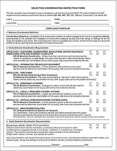
Figure 1: Example of a selective coordination inspection form for electrical inspectors.
Compliance with Selective Coordination Requirements
In order to verify compliance with requirements for selective coordination, time-current characteristic (TCC) curves can be constructed to show the opening and clearing times of the overcurrent devices for all values of overcurrents up to the maximum available fault current. In order to achieve selective coordination, there can be no overlap of TCC curves at the fault current, which the devices will see. Figure 2 is a plot of the TCC curves for three circuit breakers in series with each other. Also plotted is the calculated maximum available fault current. This is an example of traditional time-current curves. This TCC curve for a circuit breaker system is not selectively coordinated (as indicated by the overlap in circuit breaker time-current curves for each fault current value). As shown in figure 2, for a fault at the furthest bus downstream on the load side of the 20-A circuit breaker, all three overcurrent protective devices see a fault current of up to 6,500 amps which exceeds the instantaneous pickup of all three overcurrent protective devices. Therefore, all three circuit breakers may trip. If the trip curves are the only method being used to determine selectivity, these devices do not selectively coordinate.
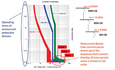
Figure 2: Example time-current curves for circuit breakers where selective coordination is not achieved by the overcurrent devices at the calculated values of available fault current due to overlap in the time-current curves.
There are options available to achieve selective coordination for the system shown in figure 2. The first and most cost effective method is to leverage circuit breaker selective coordination tables to show selectivity even though there is an overlap of curves at the specified fault current. Another method is to select circuit breakers based on TCC curves, circuit breakers that incorporate higher instantaneous trips and/or short-time delay settings that avoid overlap of the downstream circuit breaker time-current curves for the specified levels of fault current. Selective coordination tables published by the circuit breaker manufacturer indicate the maximum level of available fault current to which pairs of circuit breakers achieve selective coordination for all values of time (even below 0.01 seconds as shown traditional time-current curves). Circuit breaker manufacturers also publish coordination tables for 0.1 seconds which only confirm separation of trip curves for times beyond 0.1 seconds (overload conditions only).
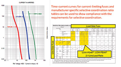
Figure 3: Time-current curves showing selective coordination of current-limiting fuses and manufacturer specific selective coordination minimum ampacity ratio table for manufacturer specific fuses.
When applying fuse type overcurrent protective devices, such as current-limiting fuses, selective coordination is achieved in a similar, but not identical, manner. Figure 3 shows an example of time-current curves for a fuse system that is selectively coordinated. Figure 3 also shows a manufacturer specific selective coordination ampacity ratio table for specific types of current-limiting fuses. As shown in the Eaton’s Bussmann Business fuse ampacity ratio table, Low-Peak® fuses have a minimum of 2:1 to achieve selective coordination. These tables assure selective coordination for all values of times (even below 0.01 seconds) and all values of fault current levels, up to the interrupting rating of the current-limiting fuses, or 200,000 amperes, whichever is less. A major difference between what was discussed above for circuit breakers and that which is discussed here for fuses is that the fuse tables make it possible to determine selectivity without having to plot time current curves up to the available fault currents.
It is important to note that fuse tables and circuit breaker tables only apply to the products of the manufacturer who published them.
Essential Electrical Systems in Healthcare Facilities
The first change in the 2014 NEC for essential electrical systems in healthcare facilities was the deletion of “Emergency System.” In the previous edition of the NEC, the emergency system comprised the life safety branch and the critical branch. This change was made to correlate with the 2012 NFPA 99 Health Care Facilities Code, and to avoid the misconception that the critical branch of a healthcare facility is considered a part of the emergency system of a facility and must comply with Article 700. Additionally, NEC 517.26 was revised to affirm that only the life safety branch of the essential electrical system must comply with Article 700. A new informational note was also added to 517.26 to refer the user to the requirements of essential electrical systems for hospitals per 517.30 and NFPA 99.
517.26 Application of Other Articles. The life safety branch of the essential electrical system shall meet the requirements of Article 700, except as amended by Article 517.
Informational Note No. 2: For additional information, see 517.30 and NFPA 99-2012, Health Care Facilities Code.
The second change to Article 517 addressed the requirements of selective coordination for the essential electrical system in hospitals. In the 2011 NEC, the entire essential electrical system was required to comply with Article 700 per 517.26. Because of this, the essential electrical system was required to comply with requirements for selective coordination per NEC 700.27. In the 2014 NEC, new 517.30(G) was added to correlate with the requirements from NFPA 99. Because of the special “defend in place” requirements in Article 517 and NFPA 99 that are intended to allow healthcare to “ride through” full or partial system blackouts, the healthcare industry believes that it can safely “ride through” any lack of selective coordination (blackouts) due to short-circuits, ground faults and arcing faults. This new section simply requires “coordination” for times of 0.1 seconds and greater. There is no mention of requirements for “selective coordination” for the essential electrical system in hospitals. As such, a system that does not comply with “selective coordination,” as shown in figure 2, may comply with “coordination” to 0.1 seconds as shown in figure 4. In addition, exceptions were added similar to those shown in 700.27 and 701.18 of the 2008 NEC. Lastly, an informational note was added to clarify that “coordination” and “coordinated” do not cover the full range of overcurrent conditions. The term coordination, as per the informational note associated with 517.30(G) which states that “The terms coordination and coordinated as used in this section do not cover the full range of overcurrent conditions.”, essentially disregards the available fault current and only seeks separation of trip curves beyond 0.1 seconds (overloads only).
517.30 Essential Electrical Systems
for Hospitals.
(G) Coordination. Overcurrent protective devices serving the essential electrical system shall be coordinated for the period of time that a fault’s duration extends beyond 0.1 second.
Exception No. 1: Between transformer primary and secondary overcurrent protective devices, where only one overcurrent protective device or set of overcurrent protective devices exists on the transformer secondary.Exception No. 2: Between overcurrent protective devices of the same size (ampere rating) in series.
Informational Note: The terms coordination and coordinated as used in this section do not cover the full range of overcurrent conditions.
The TCC Curve of figure 4 does not include the plot of available fault current. As per the informational note of this section, 0.1 second coordination levels disregard current, only looking for separation of curves for the times above 0.1 seconds.

Photo 1. Selective coordination is required for multiple elevators supplied by a single feeder.
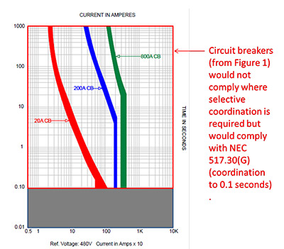
Figure 4: Compliance with coordination of 0.1 seconds does not consider all overcurrent conditions; some have coined this as only overload coordination.
It is important to note that although selective coordination is not required per the 2014 NEC for the essential electrical systems in hospitals, some electrical system designers may require selective coordination for the life safety branch of hospitals, since it provides a similar purpose to that of an emergency system for other facilities, where selective coordination is required. In addition, selective coordination may be considered by some electrical system designers as needed for some or all parts of the critical branch in hospitals to increase system reliability. As we’ll see in this article, new requirements around who performs these studies places more responsibility on the electrical system designer to make the right decisions for safety.
Critical Operation Data Systems
In the 2014 NEC, a new requirement for selective coordination was added to Article 645, which covers Information Technology Equipment. This new section, 645.27, requires selective coordination for “critical operation data systems.” Critical operation data systems are similar to critical operation power systems, where selective coordination is also required per 708.54. The definition of critical operation data system perNEC 645.2 and the requirements for selective coordination per 645.27 are shown below:
647.2 Definitions
Critical Operations Data System. An information technology equipment system that requires continuous operation for reasons of public safety, emergency management, national security, or business continuity.645.27 Selective Coordination. Critical operations data system(s) overcurrent protective devices shall be selectively coordinated with all supply-side overcurrent protective devices.
Conclusion
Selective coordination is a key requirement for increasing system reliability and safety of critical systems. Over the past several code cycles, the requirements for selective coordination have expanded to new types of systems. In the past code cycle, the definition of Coordination (Selective) has been revised to clarify the intent of the definition. Additionally, documentation requirements have been added for select critical systems to aid enforcement and compliance with the requirements for selective coordination. For electrical inspectors, a selective coordination inspection form may be used to communicate the requirements and needed documentation for systems that require selective coordination. To show compliance with selective coordination, time-current curves and/or manufacturer specific selective coordination tables for both circuit breakers and fuses can be used. This documentation must be provided to the designer, installers, inspectors, maintainers and operators of the system. Finally, because of the “defend in place” philosophy of healthcare facilities, the requirements for essential electrical systems in healthcare facilities have been lowered to only require “coordination” for times of 0.1 seconds and greater, although some electrical system designers may choose to apply selective coordination to these systems to increase reliability and safety.