At first glance, the obvious answer is: Photovoltaic (PV) systems are no different from other electrical power systems, and of course they should be grounded as required by the National Electrical Code. The real question is: How critical is grounding PV systems?
Let us examine the various features of PV systems that relate to grounding. Most PV modules have aluminum frames and circuit conductors. They must be installed where trees, poles, or other high objects do not shade them. These systems are frequently installed on the roofs of buildings and are frequently the highest metallic objects in the vicinity. As such, they are subject to surges from nearby lightning strikes. In fact, mounted high on buildings, they may act like air terminals (lightning rods).
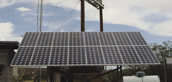
Photo 1. Stand-alone PV system near power lines
With the significant monetary incentives in California, New Jersey, New York, Pennsylvania and elsewhere, numerous PV systems are being installed in urban areas near power transmission lines (see photos 1 and 2). As a result of severe weather, earthquakes, or man-made disasters, these transmission lines may come into contact with the PV array in its exposed location.
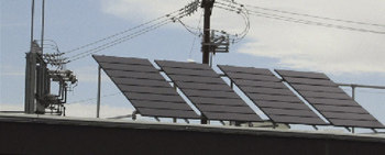
Photo 2.Utility-interactive PV system under power lines
The most common types of utility-interactive PV systems use inverters that operate up to 600 volts direct current (dc). This voltage is significantly higher than the normal 208–240-volt ac found in dwellings and small commercial buildings. Keeping those voltages safely under control during the rare fault condition is certainly important, a strong case for proper grounding.
PV modules can be expected to generate dangerous amounts of energy (shock and fire hazards) when exposed to the sunlight for the next 40–50 years or longer. This is significantly longer than the life expectancy of most other electrical generators. Today, deterioration of residential wiring systems only slightly older is becoming a problem, and the wiring systems used in PV systems are exposed to the harsher outdoor environment. Durable grounding can help to minimize future problems.
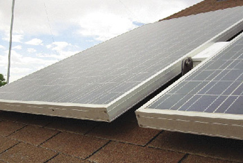
Photo 3. Aluminum-framed PV modules
Do PV systems require quality grounding? Yes, they do, for all of the reasons identified in the Code and then some. All PV systems will require equipment grounding with the equipment grounding conductors. Most of the equipment has metal enclosures that should be grounded by the normal methods. If we look closely at PV systems, we see two areas where they present some unique grounding issues. The first is the grounding of the frames of PV modules (see the sidebar). The second area relates to grounding the circuit conductors.
PV Inverters Create Separately Derived Systems
The second area focuses on the fact that PV systems have dc circuits and ac circuits and both must be properly grounded. Although the NEC has parts of Article 250 that deal with the grounding of ac systems and parts that deal with the proper grounding of dc systems, it does not specifically deal with systems that have both ac and dc components.
In Article 100, the definition of separately derived systems includes PV systems and, in most cases, this is correct. Most, but not all, PV systems (both stand-alone systems and utility-interactive systems) employ an inverter that converts the dc from the PV modules to ac that is used to feed loads or the utility grid. These inverters use a transformer that isolates the dc side of the system from the ac side. The grounded dc circuit conductor is not directly connected to the grounded ac circuit conductor. Although we normally think of separately derived systems as applying only to ac systems with transformers, in fact, the isolation between ac and dc circuits in PV inverters makes many PV systems also separately derived.
AC Grounding
DC Grounding
The dc side of the system must also be grounded when the system voltage (open-circuit PV voltage times a temperature-dependent constant) is above 50 volts. See NEC 690.41 for more details. NEC Table 690.7 gives the temperature-dependent constant, and the application of this constant usually indicates that PV systems with a nominal voltage of 24-volts or greater must have the dc side grounded. Only infrequently, do we find 12-volt dc systems that do not have one of the dc circuit conductors grounded, and even those systems must have an equipment grounding system (see NEC 690.43). Nearly all utility-interactive PV systems operate with a nominal voltage of 48 volts or higher so they must have one of the dc circuit conductors grounded.
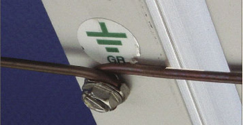
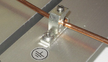
Photo 5. Improperly installed grounding hardware
Properly grounding the dc side of a PV system is somewhat complicated by NEC 690.5 that requires a ground-fault protection device (GFP) on some PV systems. If the PV array is mounted on the roof of a dwelling, 690.5 requires that this device be included in the system to reduce fire hazards. Many utility-interactive inverters have an internal GFP. Inverters (both stand-alone and utility-interactive) that are used in systems with PV modules mounted on the roofs of dwellings that do not have the internal GFP must have an external GFP installed in the system (see photo 6). In nearly all cases, these GFPs (either inside the inverter or externally mounted) actually make the grounded circuit conductor-to-ground bond.
For systems employing a GFP, there should be no external bonding conductor, and to add one to these systems would bypass the GFP and render it inoperative. A fine print note has been proposed for the 2005 NEC to alert installers and inspectors to the danger.
690.42 FPN: Equipment containing ground-fault protection devices as required by 690.5 will have the single-point for dc grounding included as a part of the equipment. Any grounding point installed externally to the equipment would bypass any internal ground-fault protection device.
In most dc systems, the negative conductor is the grounded conductor.
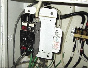
Photo 6. External ground-fault protection device
A dc bond inside the inverter with a GFP or a dc bond in a GFP external to the inverter establishes the need for and connection location of a dc grounding electrode conductor. Some inverters with an internal GFP have a terminal designated for connecting the usual 8 AWG to 4 AWG grounding electrode conductor. Other inverters are lacking this connection. Some inverter manufacturers are providing a field-installed lug kit for this connection that has been evaluated by their listing agency. PV systems with externally installed GFP devices will have an appropriate connection place (and instructions) for the grounding electrode conductor.
PV systems that do not have PV modules mounted on the roofs of dwellings are not required to have the 690.5 GFP, but many inverters in those systems will have it anyway. In those systems not requiring or having a GFP, then the dc bonding jumper may be installed at any single point on the PV output circuits, and this is where the dc grounding electrode conductor should be connected.
And The Other End of the Grounding Electrode Conductor?
There are two options for routing the ac and dc grounding electrode conductors, and these should be clarified in a proposed change to the 2005 NEC. Here is the wording of the proposal:
690.47(C) Systems with Alternating-Current and Direct-Current Grounding Requirements
Photovoltaic power systems with both alternating-current (ac) and direct-current (dc) grounding requirements shall be permitted to be grounded as described in (1) or (2).
(1) A grounding electrode conductor shall be connected between the identified dc grounding point to a separate dc grounding electrode. The dc grounding electrode conductor shall be sized according to 250.166. The dc grounding electrode shall be bonded to the ac grounding electrode to make a grounding electrode system according to 250.52 and 250.53. The bonding conductor shall be no smaller than the largest grounding electrode conductor, either ac or dc.
(2) The dc grounding electrode conductor and ac grounding electrode conductor shall be connected to a single grounding electrode. The separate grounding electrode conductors shall be sized as required by 250.66 (ac) and 250.166 (dc).
Summary
Grounding PV systems is at least as important as grounding other electrical power systems. Unique PV hardware such as the aluminum framed modules and inverters that isolate the dc circuits from the ac circuits dictate that extra attention should be directed toward making the grounding system reliable and durable.
By the way, a proposal for the 2005 NEC may eliminate the requirement to ground one of the circuit conductors in some PV systems.
For Additional Information
If this article has raised questions, do not hesitate to contact the author by phone or e-mail. E-mail: jwiles@nmsu.edu Phone: 505-646-6105
A PV Systems Inspector/Installer Checklist will be sent via e-mail to those requesting it. A copy of the 100-page Photovoltaic Power Systems and the National Electrical Code: Suggested Practices, published by Sandia National Laboratories and written by the author, will be sent at no charge to those requesting a copy with their address by e-mail. The Southwest Technology Development web site (http://www.nmsu.edu/~tdi) maintains all copies of the “Code Corner Columns” written by the author and published in Home Power Magazine over the last 10 years.
The author makes 6–8 hour presentations on “”PV Systems and the NEC”” to groups of 40 or more inspectors, electricians, electrical contractors, and PV professionals for a very nominal cost on an as-requested basis.
Sidebar
Grounding PV Modules
Grounding PV modules to reduce or eliminate shock and fire hazards is necessary but difficult. We typically use copper conductors for electrical connections and the module frames are generally aluminum (see photo 3). Copper and aluminum don’t mix as was discovered in numerous fires in houses wired with aluminum wiring in the 1970s. Many have a mill finish, some are clear coated, and some are anodized for color. The mill finish aluminum and any aluminum that is scratched quickly oxidizes. This oxidation and any clear coat or anodizing form an insulating surface that makes for difficult long-lasting, low-resistance electrical connections (e.g., frame grounding). The oxidation/anodizing is not a good enough insulator to prevent electrical shocks, but it is good enough to make good electrical connections difficult.
Underwriters Laboratories (UL) who tests and lists all PV modules sold in the U. S. requires very stringent mechanical connections between the various pieces of the module frame to ensure that these frame pieces remain mechanically and electrically connected over the life of the module. These low-resistance connections are required because a failure of the insulating materials in the module could allow the frame to become energized at up to 600 volts (depending on the system design). The National Electrical Code requires that any exposed metal surface be grounded if it could be energized. The installer of a PV system is required to ground each module frame. The Code and UL Standard 1703 require that the module frame be grounded at the point where a designated grounding provision has been made. The connection must be made with the hardware provided using the instructions supplied by the module manufacturer.
The designated point marked on the module frame must be used since this is the only point tested and evaluated by UL for use as a long-term grounding point. UL has established that using other points such as the module structural mounting holes coupled with typical field installation “techniques” do not result in low-resistance, durable connections to aluminum module frames. If each and every possible combination of nut, bolt, lock washer, and star washer could be evaluated for electrical properties and installation torque requirements and the installers would all use these components and install them according to the torque requirements (we all have and use torque wrenches and torque screw drivers don’t we?), it might be possible to use the structural mounting holes for grounding.
Most U.S. PV module manufacturers are providing acceptable grounding hardware and instructions. Japanese module manufacturers are frequently providing less-than-adequate hardware and unclear instructions. Future revisions of UL 1703 should address these issues. BP Solar is to be congratulated for getting their module listing to include making new grounding points at other locations than the marked points.
In the meantime, installers have to struggle with the existing hardware and instructions, even when they are less than adequate. Southwest Technology Development Institute has identified suitable grounding hardware and provides that information when installers ask about grounding—a frequent topic. And, yes, we are using the hardware and methods described below to ground PV modules in our new inverter test facility when the modules have less than satisfactory grounding hardware or no hardware at all.
For those modules that have been supplied with inadequate or unusable hardware or no hardware at all, here is a way to meet the intent of the Code and UL Standard 1703. Of course, ignoring the manufacturer’s instructions and hardware (however poor) is done at one’s own risk.
For those situations requiring an equipment grounding conductor larger than 10 AWG, a thread-cutting stainless steel 10-32 screw can be used to attach an ILSCO GBL4 DBT lug to the module frame at, or adjacent to, the point marked for grounding (see photo 4).
A #19 drill is required to make the proper size hole for the 10-32 screw. The 10-32 screw is required so that at least two threads are cut into the aluminum (a general UL requirement for connections of this kind). The thread-cutting screw is required so that an airtight, oxygen-free mating is assured between the screw and the frame to prevent the aluminum from re-oxidizing. It is not acceptable to use the hex-head green grounding screws (even when they have 10-32 threads) because they are not listed for outdoor exposure and will corrode eventually. The same can be said for other screws, lugs, and terminals that have not been listed for outdoor applications. Hex-head stainless steel “tech” screws and sheet metal screws do not have sufficiently fine threads to make the necessary low-resistance, mechanically durable connection. The only thread-cutting, 10-32 stainless steel screws that have been identified so far have Phillips heads; not the fastest for installation.
The ILSCO GBL4 DBT lug is a lay-in lug made of solid copper and then tin-plated. It has a stainless steel screw to hold the wire. It accepts a 14–4 AWG copper conductor. It is listed for direct burial use (DB) and outdoor use and can be attached to aluminum structures (the tin plate). The much cheaper ILSCO GBL4 lug looks identical, but is tin plated aluminum, has a plated screw, and is not listed for outdoor use. I have not been able to identify an alternative to the GBL4 DBT, but continue to search.
If the module grounding is to be accomplished with a 14–10 AWG conductor, then the ILSCO lug is not needed. Two number 10 stainless-steel flat washers would be used on the 10-32 screw and the copper wire would be wrapped around the screw between the two flat washers that would isolate the copper conductor from contact with the aluminum module frame.
Yes, we would all like to use the module mounting structure for grounding. The Code allows metal structures to be used for grounding and even allows the paint or other covering to be scraped away to ensure a good electrical contact. We see numerous types of electrical equipment grounded with sheet metal screws and star washers. This works on common metals like steel, but not on aluminum due to oxidation.
Unfortunately, many PV systems are being grounded improperly even when the proper hardware has been supplied. Photo 5 shows that even the proper hardware can be misused. Here, the stainless-steel isolation washer has been installed in the wrong sequence and the copper grounding wire is being pushed against the aluminum frame, a condition sure to cause corrosion and loss of electrical contact in the future.