This article addresses one of the largest connections within a dwelling unit and, in all likelihood, the largest branch circuit: the range and/or the oven. Although obvious that we should ensure that it is being connected properly, this connection is seldom checked.
All-electric units can be up to 50 amps. The possibility of an improperly installed and connected unit can result in a higher amperage fault, which may result in dramatic failure. These connections are located where they are not usually visible, and they may be in storage areas, both of which add to the possibility of increased danger.
Let’s explore the installation process for these electrical appliances. The electrician provides the branch circuit for the unit using a 4-wire circuit consisting of two ungrounded, one grounded, and one equipment grounding conductor. The conductors are roughed into a junction box, which may be plastic or metal. If it is metal, then a connection is made to the box with the equipment grounding conductor. When installed into a plastic box, we may have a couple of issues. First, a normal receptacle or switch box that has pre-formed cable entries for 14 to 10 AWG cable assemblies is not approved for larger cable assemblies such as 8 to 6 AWG four-conductor cable assemblies. Therefore, the installation would require a box with factory cable entries listed for larger cables or traditional knockouts and a properly sized and listed cable connector. Due to the fact we have a plastic box, there is no connection point for an equipment grounding conductor — yet. See Photo 1.
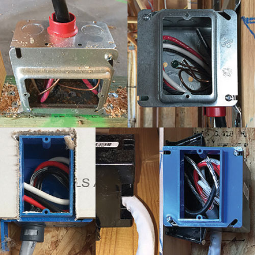
During the trim process, the electrician installs a blank cover on the box as the range or oven is not on site yet. Now we may start to have a problem. If we have a metallic blank cover installed on the plastic rough-in box, do we ground it? No, because it is just temporary? If it has a knock-out in the cover, is this the location where the connection will be made? There are several unknowns at this point.
Also, who does the final connection when the appliance finally arrives on site? Does the electrician come back and make the connection? This would make sense since this is an electrical connection of a large branch circuit that we should make sure is done safely and is arguably just as important as the main service connections or the sub-panel connections, right?
I wish this were the case. However, for well over 20 years while involved in the dwelling construction environment, seldom did we ever see the electrician make the final connection of these appliances. The final installation is typically performed by the truck driver/delivery person, who is trying to perform his work as fast as possible. When we checked with the appliance suppliers, we asked if they hired any electricians to do these installs and the answer was no. So we have an unqualified delivery person making the final connections and completing the installations. Personally, this does not give me a warm feeling.
So while we are on my personal feelings, let me expound on the issue as I see it. From a liability perspective, I have always liked a clear dividing line between the work performed by the electrician and the utilization equipment. A great way to establish this dividing line is at the receptacle (plug) connection. The electrical system from the main service to the receptacle face is the responsibility of the electrician; everything plugged into that receptacle is the responsibility of the owner or maker of the equipment being used.
So with that said, why don’t we follow this procedure for range/oven installations? If I am the electrician and I install a properly sized receptacle – say, a 50 amp 4-wire unit — then I have done my job, and my responsibility stops at the face of that receptacle. When the appliance is delivered, they can install a NEMA approved 125/250V 50A range power supply cord and simply plug in the unit. Simple, right? Too bad we do not live in a perfect world.
So is this what we see? Unfortunately no, and the main reason is that the appliance manufacturers do not make or list their equipment to be used with an approved NEMA supply cord. Instead, they have a flexible metallic raceway with conductors that may have a higher temperature rating because the outside of the appliance may have elevated temperatures. This raceway does not have a connector on the end that can be field connected.
Sometimes we see a NEMA 14-50P cord cap installed on the flex that would allow you to plug in the flexible whip. There are two issues with this, one of which is making a grounding connection to the flexible raceway. The second is that these cord caps are not tested and listed to be used on flexible raceways, only for flexible cords, so this is not a permissible use per the listing.
To do the connection correctly, the appliance installer has to use the proper connector, provide proper grounding of the metallic raceway, and make the correct electrical connections. The installation requirements from the manufacturers are very similar. I have reviewed those from the five major appliance makers, and they all have the same metallic flexible whip and similar instructions and pictorials of the proper installation. See Photo 2.
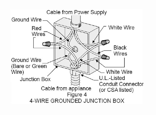
Generally, the boxes roughed in by the electricians are flush with the finished wall, which doesn’t provide any available knock-outs for the raceway entry. As you can see in the illustration of the installation instructions, they show the flexible conduit entry into the side of a junction box. So to do the installation according to the manufacturer’s instructions, a box extension would have to be installed on the flush box to follow the illustrated instructions. If the box is metal and a proper connector is used, this will solve any grounding issues.
If the rough-in box is plastic then grounding becomes a little more difficult. Do you install a metallic extension box and then ground it? If you use a plastic extension box, then you would have to use a bonding bushing on the connector to properly ground the flexible metallic raceway used by the appliance maker. Would the connector have enough threads for a lock nut and a bonding bushing? All are issues that have to be addressed.
The most common installation I have seen is a metallic blank box cover with a knock-out through which they install an angled flex connector. When installing this solution on a plastic box, the grounding again becomes an issue and should be checked.
We have covered the grounding and bonding issues, the box rough-in and making the mechanical connections of the factory flexible wiring whips. Now let’s look at the electrical connections of the circuit conductors.
The flexible whips that come attached to the appliances have copper conductors. If the branch circuit conductors are copper, then we simply have to make sure we use a mechanical connector that is listed for copper conductors and sized properly for the conductors being connected. Examples of these could be a twist on wire connector, split bolts, or insulated terminal blocks, all listed for copper connections.
The most common branch circuit wiring we commonly see for range/ovens is Type SE Style R aluminum cable assembly, generally with 6 AWG circuit conductors. This represents a connection issue that may seem mundane and easy to solve for electricians. However, to appliance delivery people who are not electricians, this could become an issue due to code ignorance. The appliance installers are there to do their job as fast as possible and move to the next delivery. They generally carry twist on wire connectors. A flex ninety fitting gets put on the end of the flex, into a blank metallic cover it goes, four twist on connectors, and two screws to secure the cover to the box, then off they go.
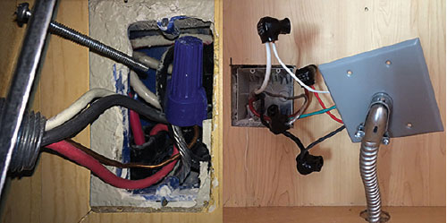
So what is the proper way to make the dissimilar metal terminations? First, you have to find a connector that is listed for both copper and aluminum. This is not as hard as it seems, but you have to verify. There are CU/AL split bolts, which will require a proper insulating material to be installed on the split bolt, such as rubber tape and then electrical tape to equal the wire insulation thickness. Another way is to find an insulated terminal block that is listed CU/AL. These are usually made from insulated aluminum terminal blocks and provide an excellent terminal for the aluminum conductor. However, they have to have a copper flash and then a tin plating to be approved for the copper conductor. So they need to be checked, and they should clearly be listed CU/AL. See photos 3 and 4.

When I was electrical inspections supervisor, I would tell my inspectors doing residential work that they didn’t need to check every appliance, but they did need to randomly check by asking the superintendent to pull an oven from time to time and check the connections. If they found the connections done incorrectly, then we would have them pull more to insure the others were done properly. If those were good, we would continue with random checks. Word gets out, and soon the issues get cleared up since the builders hate to pull these units over and over again.
A superintendent for one of the larger buildings locally, who I used to work with, specifically checks the appliance installations on his projects. He kindly provided some of the photos for this article. He has shared that they have had issues with improper installations, and he feels it is important to check all the connections.
The idea of having a clear dividing line between the electricians and the appliance installer will help to protect the electrician when and if a failure occurs and help prove who is responsible for the liability issues. When a failure happens, it is usually the electrician that gets the call and the blame. After all, it is an electrical issue right? However, we know that it is probably an issue caused by the appliance installer, who is long gone and never gets the blame.
Since these appliances are often the largest loads connected within our dwelling units, with up to fifty amps of current that could heat and cause an arcing condition and result in a fire condition, it is critical to make sure the connections are done properly. This is probably an inspection point that many inspectors never check. I hope I have shared with you some of the issues and possibilities of failures that could be caused by not getting these done in an electrically safe manner. If grounding is not done right, we could energize the entire appliance, including the metallic flex that then becomes a conductor and has the possibility of heating up like a toaster coil, easily igniting nearby combustibles. This type of failure is all too possible when we do not use the proper connectors for the circuit conductors.