During the past thirty years, flooding in the U.S. has resulted in an annual average of nearly $8 billion in flood losses (adjusted for inflation) and eighty-two fatalities.1 Because of anticipated changes in climate conditions, stronger storms and rising sea levels, the U.S. Global Change Research Program estimates flood risk to coastal and interior flood-prone areas is only expected to increase, along with its associated losses.2
A significant portion of flood damage is attributed to critical building systems, including mechanical, electrical, plumbing, and other utility elements. Residents, communities, and businesses are all impacted when building utility systems are damaged and cause delays in post-flood building re-occupancy.
This article illustrates the design and construction of typical residential utility systems that comply with the National Flood Insurance Program (NFIP) requirements for construction of new residential structures in flood-prone areas. It is also useful when evaluating structures that will undergo substantial improvement, guiding users to meet floodplain management regulations and building code requirements.
Even if compliance is not required, many building owners may find that applying mitigation measures described in this article will not only reduce future flood damage but also facilitate recovery after flooding
Mitigation Planning
When planning and, ultimately, installing building utility systems, the basic process illustrated in figure 1 should be followed to ensure selection of appropriate flood risk reduction measures for building utility systems that satisfy building code requirements, manufacturer specifications, and local floodplain management regulations.

Regulated Flood Hazard Areas
The National Flood Insurance Program (NFIP) can offer affordable flood insurance by using risk management (floodplain management) principles to reduce flood losses. The federal government established the standard for mapping and regulating flood risk to be the one-percent-annual-chance flood, also referred to as the “base flood” and sometimes called the “100-year flood.” The base flood represents a magnitude and frequency that has a one percent chance of being equaled or exceeded in any given year. A flood of this magnitude has a 26 percent (one in four) chance of occurring over the life of a 30-year mortgage. The one-percent-annual-chance flood standard has been used since the NFIP’s inception and is used in more than 22,200 participating communities.
Floodplains are areas subject to inundation from floodwaters. The Federal Emergency Management Agency (FEMA) prepares Flood Insurance Studies (FISs) and defines and delineates areas at risk for one-percent-annual-chance flooding on Flood Insurance Rate Maps (FIRMs). These areas are called Special Flood Hazard Areas (SFHAs). Communities that participate in the NFIP adopt FISs and associated FIRMs, which are then used to regulate development. FISs are prepared using specified engineering models and the physical, hydrologic, and climate conditions in effect at the time the studies were conducted. The resulting FIRMs are drawn incorporating the FIS data. FIRMs and FISs are thus a “snapshot” of flood risk at a certain time and can become outdated as topographic, hydrologic, land use or climate conditions change or as engineering methods, data collection and models improve. The FIS, FIRMs and associated flood data adopted by communities are referred to as “effective” until replaced by a new FIS or FIRM.
NFIP regulations [44 CFR §60.3(a)(3)] state that:
All new construction and Substantial Improvements shall be constructed with electrical, heating, ventilation, plumbing, and air conditioning equipment and other service facilities that are designed and/or located so as to prevent water from entering or accumulating in the components during conditions of flooding.
This requirement is reflected in the IRC, where Section 322 requires the following to be elevated above the flood protection level:
- heating, ventilating, duct systems, and air conditioning systems, equipment and components;
- electrical systems, equipment, and components;
- plumbing appliances, plumbing fixtures; and
- other service equipment.
Exceptions are allowed only when components are designed and installed to prevent water entry or where equipment can resist flood loads, including buoyancy. While it may be practical to prevent water entry into a few utility components (e.g., sealed water piping), it is often difficult to resist flood forces that tend to crush or dislodge submerged equipment. Thus, elevating utility systems is often the only practical option for flood protection.
Elevation and Relocation
This section presents an overview of the mitigation measures available to bring utility systems, equipment, and components into compliance with NFIP requirements for new construction or Substantial Improvement and repair of Substantial Damage. These measures are generally applicable to both residential and non-residential buildings, although some may be used only for non-residential buildings when compliance is required. When compliance is not required, certain measures may also be used to reduce flood vulnerability for existing buildings, resulting in reduced recovery time and cost.
Elevation: Installing or locating utility systems and components at or above the flood protection level required by local floodplain management regulations or building codes.
Relocation: Moving existing utility systems and components previously installed below the base flood elevation to less vulnerable locations, preferably above the flood protection level required for new construction.
Component protection (Dry floodproofing): This measure involves the installation of flood-resistant barriers and can be used to protect vulnerable components of MEP systems. The NFIP does not recognize dry floodproofing for residential buildings as a mitigation measure; therefore, it is not an option for new construction and Substantially Improved buildings. Nonetheless, dry floodproofing can reduce flood risks in instances other than Substantial Improvement or Substantial Damage.
Other Measures (Wet floodproofing): Partial system mitigation can reduce flood damage. Certain HVAC components that have some resistance to flood damage, and can be readily cleaned and repaired, may be used instead of elevation or dry floodproofing. The NFIP, the IRC and ASCE 24 allow components to be exposed to floodwater, provided they can resist flood forces and are designed and installed to prevent floodwater entry. However, it can be difficult to obtain flood-resistant utility components, particularly those that prevent floodwater entry and can resist flood loads.
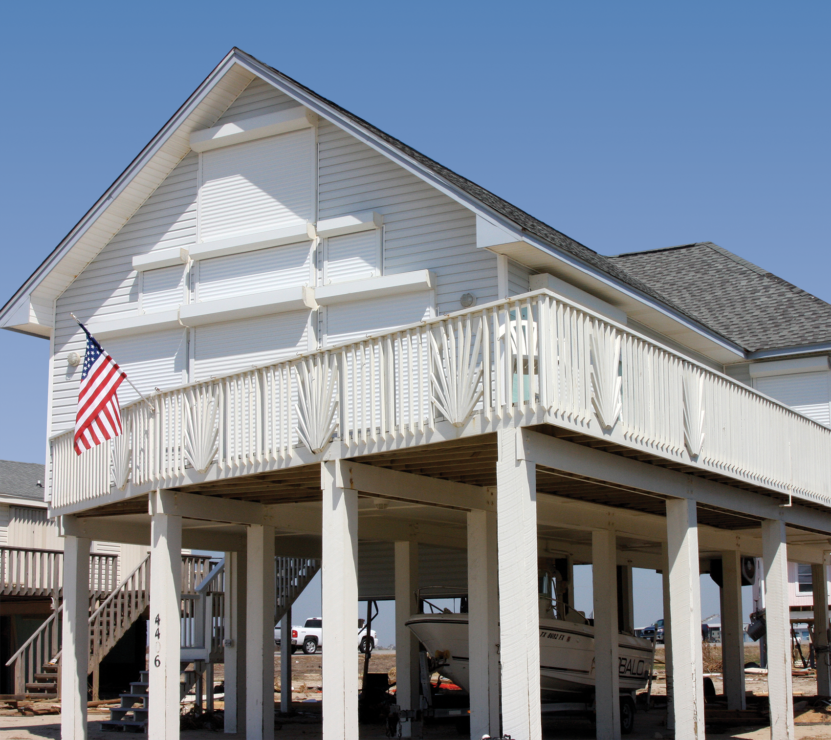
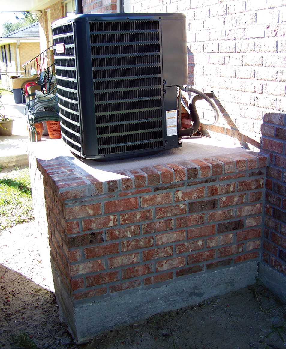
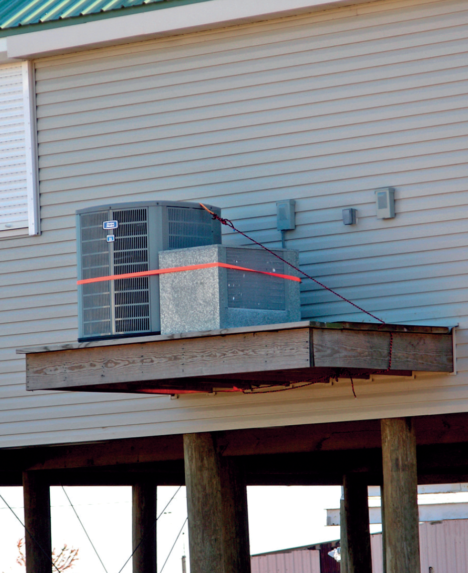
Compliance with elevation or relocation requirements generally entails installing exterior equipment on platforms, pedestals, or the rooftop. Interior equipment can be installed on platforms inside enclosures below elevated buildings or installed or relocated to floors at or above the required elevation. Pedestals are typically masonry structures (see photo 1). Platforms may be free-standing, self-supporting structures or they may be cantilevered from, or knee-braced to, buildings (see photo 2). In flood hazard areas identified as Zone V on FIRMs, pedestals must not be sited under or immediately adjacent to buildings because they could obstruct the free passage of floodwater and waves.
Depending on building characteristics, some systems or equipment may be suspended from walls, floor systems, or roof framing to raise them above the required elevation. Additionally, protection must be provided for any element or component that extends from the ground to the building, such as water supply pipes, sanitary drainage pipes, gas and fuel lines, or underground electric service.
Replacement of equipment and systems that serve existing buildings provides an opportunity to reduce vulnerability to future flooding. In some jurisdictions, when buildings are “Substantially Improved” or repaired after incurring “Substantial Damage,” the buildings and their equipment and utilities must be brought into compliance with the same requirements that apply to new construction. Elevating or relocating equipment achieves compliance. Dry floodproofing (also called component protection) below the elevation required for protection by using substantially impermeable, watertight vaults or utility rooms may achieve compliance in non-residential buildings.
When replacement of equipment and systems is not part of “Substantial Improvement,” relocating equipment from lower to higher elevations provides some protection against flood damage and may help occupants return to the building more quickly after a flood. Relocation is especially effective when equipment is moved from below-grade areas (i.e., basements) to higher floors. In some cases, small above-ground additions can be added to existing buildings to serve as utility rooms for relocated equipment.
Electrical Systems
A typical residential electrical system is shown in figure 2. Power originates from a utility transformer that generally provides single phase 120/240-volt power for detached one- and two-family dwellings. The transformer may be pole- or pad-mounted. Larger multi-family residential buildings may receive single phase 120/208-volt power derived from a three-phase system, but flood recommendations are the same in either case. For clarity, only portions of the branch circuits and electrical devices are shown.
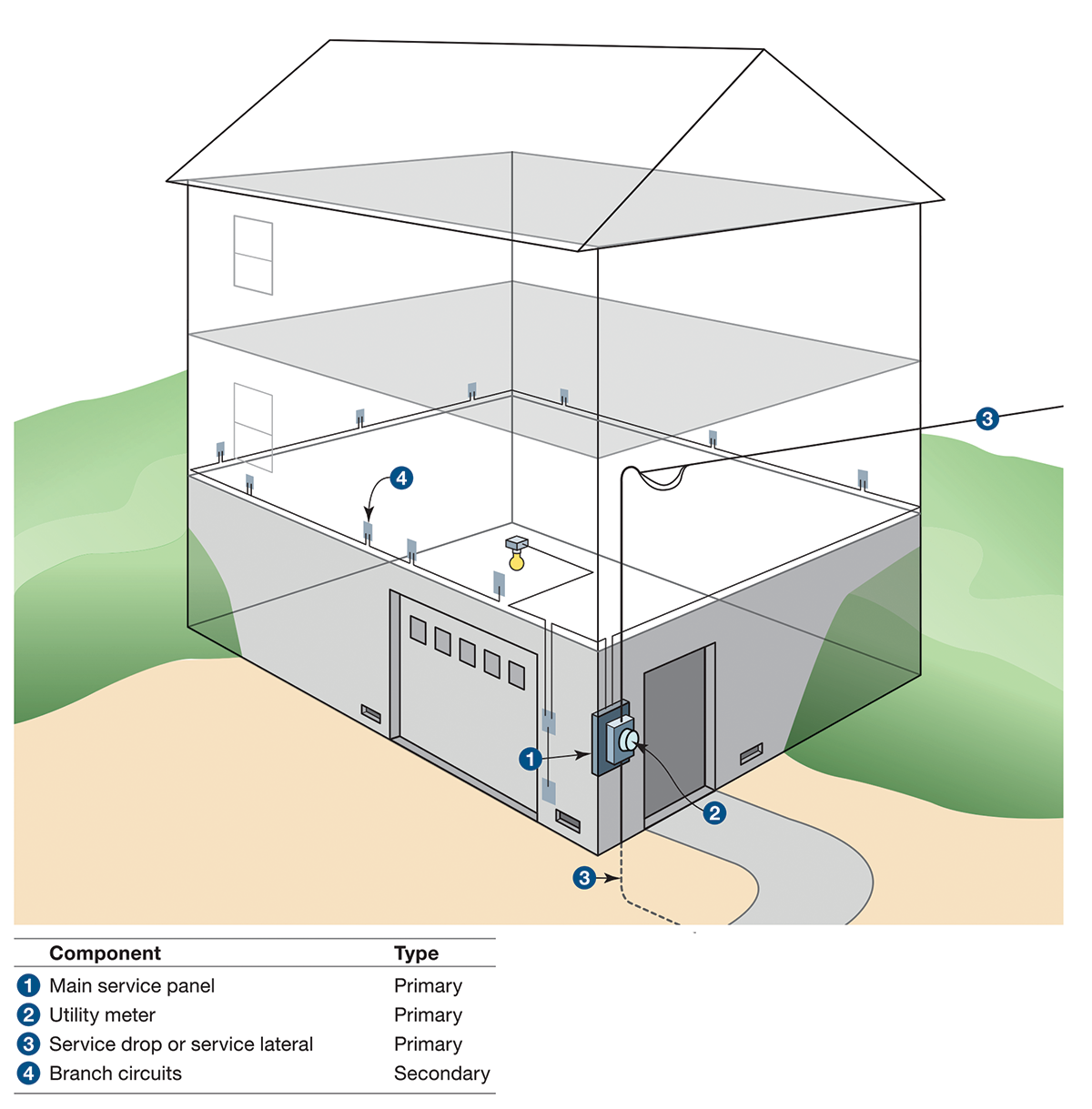
From the transformer, power flows through an overhead service drop or an underground service lateral to a utility meter where power consumption is measured for billing purposes. Utility meters are typically centered about five feet above grade so that they may be read and easily removed when a customer’s power needs to be shut off.
From the utility meter, power enters the building and feeds the main service disconnect, which may be a separate enclosed fuse or circuit breaker or may be mounted in the home’s main panel. Most homes have a single main panel; larger homes, homes with additions, and those that have a combination of new and legacy wiring may have two or more panels. When present, electrical feeders connect panels that are downstream of the main panel to the main panel.
Panels contain overcurrent devices such as circuit breakers or fuses that protect branch circuit wiring. The branch circuits are either 120 volt (lights and outlets) or 240 volt (appliances like ranges, ovens, electric water heaters and air conditioning units that draw significant power).
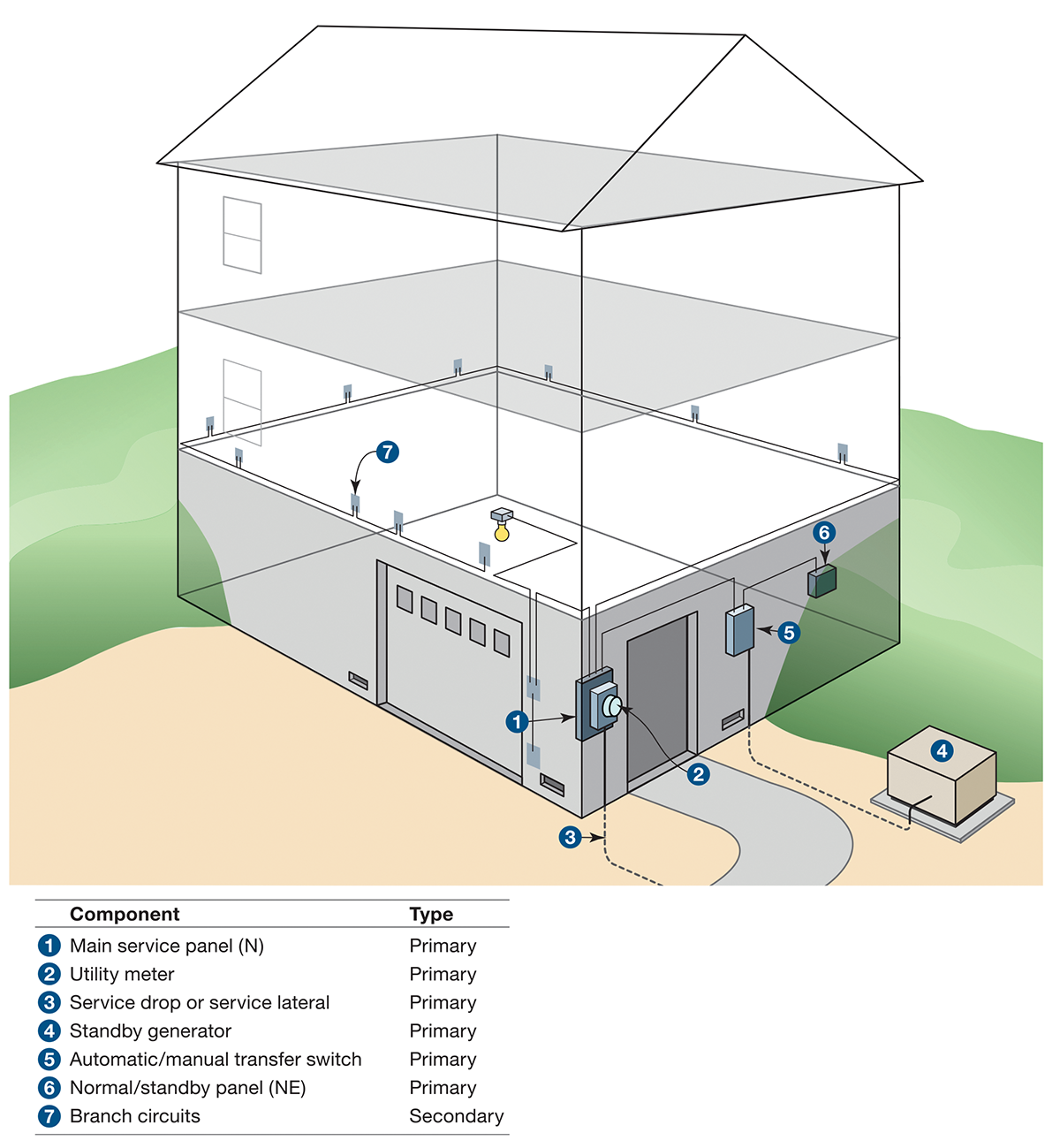
Homes that have standby generators or provisions to connect portable generators are enabled by transfer switches to draw power from the utility company, or from the generator if utility power is not available. Transfer switches are either automatic transfer switches (ATSs) or manual transfer switches (MTSs). ATSs automatically sense a loss of utility power, send a signal to start the generator and operate to transfer loads from the utility to the generator. MTSs require manual transfer of power from the utility to the generator. Homes with on-site generators may have ATSs or MTSs; homes with properly designed provisions to connect temporary generators typically have MTSs.
Figure 3 shows a home supplied with an on-site standby generator. The home features two branch circuit panels. One of the panels (designated “N” for normal power) is the main service panel, which is supplied only from the utility. The other panel (designated “NE” for normal/emergency) is supplied from the transfer switch that receives power from the utility through the main service panel, or from the standby generator. Loads considered important such as the refrigerator, freezer, well pump, water heater, and selected lights and receptacles are typically supplied from the normal/emergency panel. Loads deemed less important — particularly those that draw significant power like electric ranges, air conditioning units, and clothes dryers — are often supplied by the normal power panel to allow a small standby generator to supply the home.
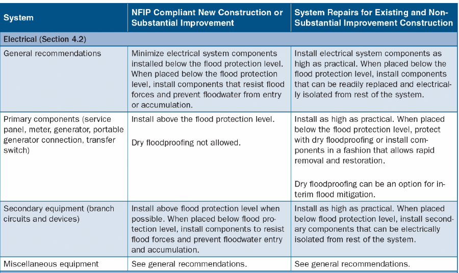
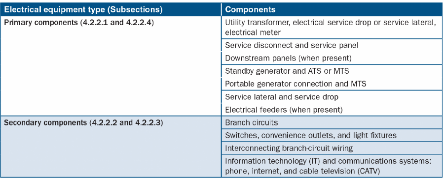
Electrical systems can be divided into primary and secondary components. Primary components are needed for any portion of the system to function; secondary components can be damaged or rendered inoperative without causing a total loss of function for the electrical system. Table 2 lists the typical components of a residential system and distinguishes them as primary or secondary components.
Flood Risks to Electrical Systems
Floodwater can damage nearly all electrical system components except those designed for submerged applications. Damage to electrical system components can create fire and electrocution hazards during a flood, extended power outages, and delay the reoccupation of a home after a flood event.
For new construction and Substantially Improved buildings, codes allow electrical devices to be installed below the regulatory flood protection elevation, but only require that electrical devices be suitable for wet locations. Electrical devices suitable for wet locations can still be damaged if submerged in floodwater; therefore, only equipment listed for at least temporary submersion is recommended for use below the flood protection level. The National Electric Code (NEC) Table 110.28, Enclosure Selection, lists the degree of protection for various electrical enclosures. Only National Electrical Manufacturers Association (NEMA) Type 6 and 6P enclosures are listed for protection from submersion.
The primary components of an electrical system that may be vulnerable to flood damage include pad-mounted utility transformers, underground electrical service laterals, electrical utility meters, service disconnect or service panels, and standby power equipment like an on-site generator, transfer switch and portable generator connectors. Electrical feeders that connect the primary components are considered primary components. Electrical service drops, which are typically placed more than 10 feet above ground level, are usually not at risk of flooding. Supply equipment placed at lower elevations can be vulnerable to floods.
Secondary components that are vulnerable to flood damage include all equipment and wiring that is not specifically designed for submerged installations. These include switches, convenience outlets, light fixtures, junction boxes, and interconnecting wiring not suitable for submerged installations.
Mitigation for Electrical Systems
Mitigation actions for electrical systems should focus on primary components; secondary components should be mitigated where practical. Primary and secondary components should be placed as high above the flood protection elevation as possible. Placing as many components as high as possible should be the design goal for all new construction and Substantially Improved residential buildings.
Component relocation is generally the most appropriate mitigation approach for residential electrical systems. This is an option when the residence is not undergoing substantial improvement. Component reconfiguration is generally not an option because most primary electrical components cannot be re-configured to allow installation at higher elevations. In-place elevation is an option, but NEC contains specific requirements for access to electrical equipment that may limit in-place elevation. Those criteria apply to the service disconnect, service panel, and transfer switches. In-place elevation must satisfy NEC requirements.
If components must be located below the required flood elevation, they should be designed and installed to minimize effects on elements of the electrical system not damaged by floodwater. To accomplish this, wiring and devices installed below the flood protection elevation should be supplied from dedicated branch circuits separate from those that supply equipment above the flood level. Also, for equipment that is vulnerable to floodwater exposure, wiring suitable for submerged applications should be used. As an alternative, wiring that facilitates the replacement of flood-damaged components should be installed. Non-metallic conduit and boxes, installed in a way that allows them to be readily cleaned after a flood and facilitates removal and replacement of flood-damaged conductors, should be considered.
Mitigating secondary components of the electrical system is often most feasible for new construction, but it is also possible when repairing damaged homes. When homes are being renovated in which interior finishes are removed or otherwise exposed, normally concealed portions of the electrical system, including the utility meter, electrical panel, and other main components, can be installed above the required flood elevation. Electrical components that need to be located below the required flood elevation can be constructed using equipment suitable for submerged applications like ground-fault circuit interrupter (GFCI) receptacles or can be installed in a manner that allows them to be electrically isolated and readily replaced if flooded.
Mitigation for Primary Components
Primary electrical system components are generally either the responsibility of the electrical utility or the property owner; therefore, the flood mitigation discussion is directed at whoever is responsible for components. Typically, the utility is responsible for the transformer, the electrical service drop or service lateral, and the electrical meter. The property owner is typically responsible for the service disconnect and service panel, downstream panels and electrical feeders, and all branch circuit wiring and devices. Standby generators or generator connections and ATSs or MTSs are also typically the responsibility of the property owner. The demarcation between utility and property owner responsibility varies between utilities so, the utility company should be contacted to discuss mitigation specifics.
The first primary component of a residential electrical system that is the responsibility of a property owner is the service disconnect, usually located in the home’s main service panel. While a specific maximum distance between the meter and the service disconnect is not specified in the NEC, the service disconnect is typically located as close as possible to the electric meter. This arrangement is intended to minimize the length of service conductors exposed to damage that are only protected from overcurrent devices in the utility system.
When the service disconnect is close to the utility meter and the meter is exposed to flooding, the service disconnect is also exposed to flooding. Preferably, the meter, service disconnect, and main service panel (if separate from the service disconnect) should all be placed above the required flood elevation. When the meter cannot be elevated, one option is to install a combination meter socket and service disconnect. This configuration allows the main service panel equipment to be elevated even if elevating the electric meter is not possible. Figure 4 shows an example of a combination meter socket and circuit breaker, which serves as the service disconnect, and depicts a combination meter socket and circuit breaker that allows the main panel to be elevated when the meter cannot be moved.
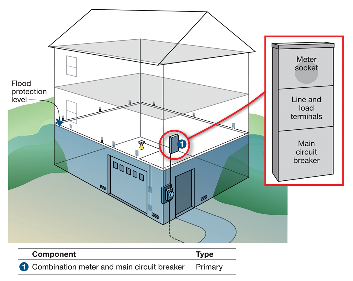
The service disconnect provides overcurrent protection for downstream equipment, alleviates the minimum distance requirement, and allows the main service panel to be elevated above the meter. Occasionally, the main service panel can be elevated above the meter without installing a combination meter and service disconnect. This can be done by routing the wiring between the meter and the main service panel outside of the home. However, this approach should be discussed with local electrical inspectors and the utility company to confirm if it is a viable option.
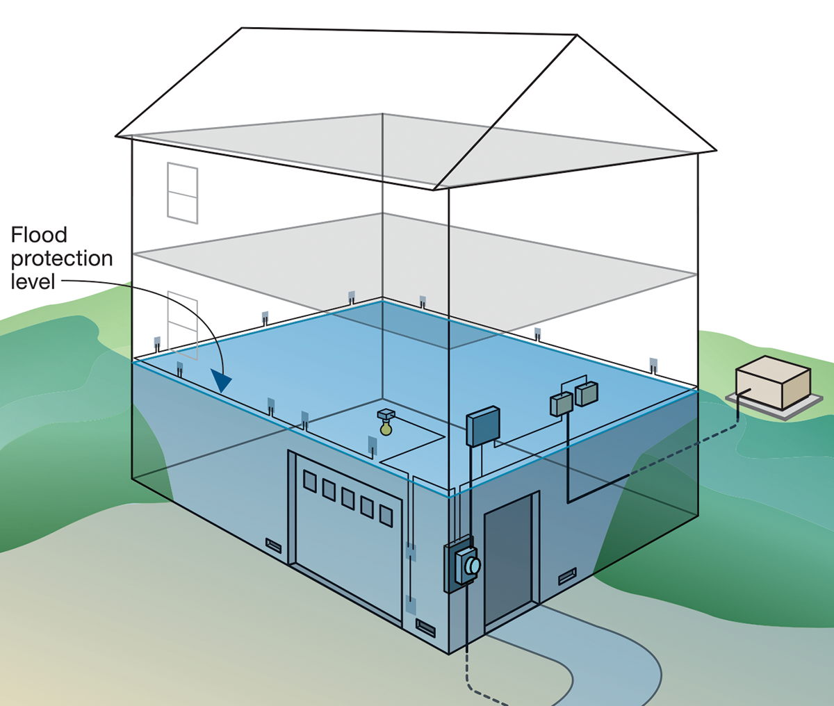
If the home has a standby generator, it, along with the transfer switch and normal/emergency panel, should be elevated above the flood protection elevation. The feeder that connects the generator to the electrical system and all control wiring should either be elevated or be suitable for submerged installations. Figure 5 shows a home served by an elevated standby generator with an elevated transfer switch and normal/emergency panel.
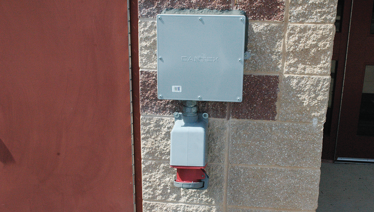
In homes provided with a flanged connection (often called a quick connect) to connect a temporary generator, the flanged connection should be placed above the required flood elevation in a place that allows the generator to be brought onto the site, quickly connected to the home, and safely refueled. Additionally, the generator should be located away from vents or windows to prevent exhaust gases from entering the home or otherwise pose a risk to occupants. Photo 3 shows a flanged connection often used to connect a temporary generator.
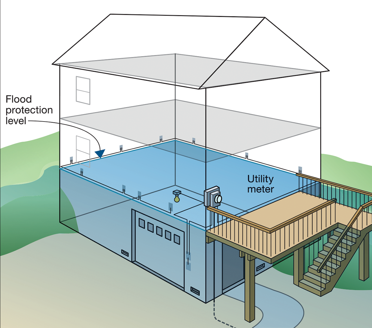
The ability to elevate electrical meters is often limited by dependence on the local utility company to enable access for reading the meter and removing it when electrical power needs to be interrupted. Typically, meters need to be placed five feet above grade, which often exposes it to flood damage. One mitigation option is to mount electrical meters over elevated decks or platforms so that the meter is above the required flood elevation. Those decks or platforms typically cannot be used only for meter access because single-use decks or platforms can fall into disrepair and become a hazard for personnel reading the meters. Owners who are considering elevating their electric meter should contact the local electrical utility to identify and coordinate meter relocation to meet the utility’s criteria.
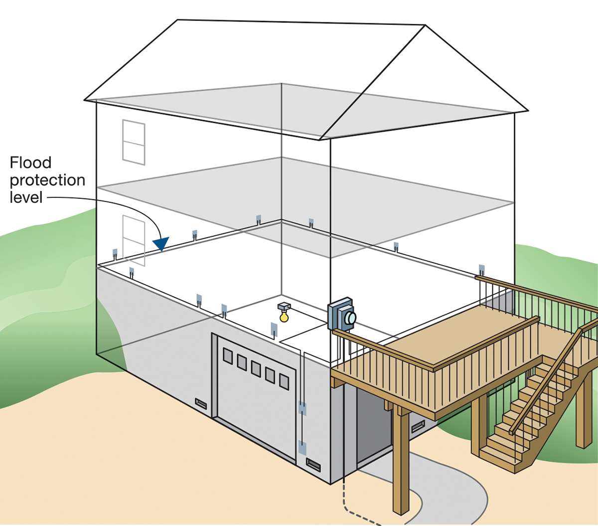
Figure 6 shows an example of an elevated deck that allows an electrical meter to be relocated above the required flood level. The dual nature of the deck is conducive to performing adequate maintenance.
Component Protection (Dry floodproofing): Dry floodproofing can be considered as an interim mitigation option for electrical system components in existing homes that are not Substantially Improved. Dry floodproofing will not lead to full compliance with building codes, standards or the NFIP.
Mitigation of Secondary Components
As with the primary components of an electrical system, the preferred approach to mitigate secondary components is to place as many as possible above the required flood elevation. For new construction and Substantial Improvement to residences where interior finishes are typically removed to create access for installing secondary components, this approach is almost always feasible. For existing homes that are not undergoing substantial improvement, many electrical components can be elevated or relocated.
Electrical devices and wiring should be located above the required flood elevation. In cases where they must be placed below this elevation and exposed to floodwater, they should be suitable for submerged locations. However, ASCE 24 and the IRC allow wiring suitable for wet locations. Wiring suitable for wet locations is less restrictive and more prone to flood damage than wiring suitable for submerged locations.
The number of required devices (receptacles, switches, lights, and other components) placed below the required flood elevation should be minimized. Those components should be supplied from separate branch circuits protected by GFCI breakers. In addition, these breakers should be clearly marked so that they can be disconnected in the event of flooding. Installing wiring in a non-metallic conduit that can readily be cleaned after a flood event can facilitate recovery. Conductors that could sustain damage can be removed and replaced more readily if they are installed in a conduit. Alternatively, junction boxes can be installed in branch circuits that allow damaged wiring below the junction box to be readily removed and replaced. Junction boxes should be placed above the required flood elevation.
In addition, all wiring and components that could potentially be exposed to flooding should be designed and installed to accelerate repair or replacement after a flood event. When elements of branch circuits are located below the required flood elevation, they should be designed to be electrically isolated from the rest of the system. Such isolation will allow for power restoration before flood-related electrical repairs are completed.
Figure 7 shows a home where flood mitigation has been completed on several primary and secondary electrical system components. Electrical devices in the basement and wiring to those devices have been elevated as high as possible. If devices cannot be elevated (e.g., a sump pump to control leakage into the basement), they are supplied by separate branch circuits and a junction box has been installed to facilitate the replacement of damaged wiring.
Mitigation of Miscellaneous Electrical Systems
IT and communications systems such as phone, internet, and cable television (CATV) components should be protected from flooding using methods similar to those of other electrical system components. Primary components like modems, video switches, splitters, and routers should be elevated. Secondary components like outlets and wiring should also be elevated. If outlets must be placed in areas exposed to flooding, the number of outlets should be minimal. GFCIs should be used and electrically isolated from the rest of the system.
Other Mitigation Considerations for Electrical Systems. In areas where moving floodwater is anticipated, electrical equipment that cannot be elevated should be installed to reduce the potential for physical damage. In coastal areas, electrical equipment should not be installed on walls designed to break away when exposed to flood loads. Equipment installed below the flood elevation should be routed along the landward side of structural members in coastal areas or along the downstream side in riverine areas. Figure 8 depicts electrical equipment routed in that fashion.

Protection of Exposed Risers, Conduits, and Cables
Underground utilities, including water supply, sanitary drainage, gas service, and electric service, are exposed to flooding when they extend from the ground supply source to elevated buildings. Connecting risers, conduits, and cables should be installed to resist anticipated flood loads, including impact from flood-borne debris. Exposed utility system connection components and equipment elements can be protected in several ways:
Installing risers, conduits, and cables on the most sheltered side of interior piles or other vertical foundation members. In coastal areas, installation on the landward side of pilings or columns provides protection. Similarly, in riverine areas, installation should be on the downstream side of columns, pilings, and posts, or located inside foundation perimeter walls (crawlspace).
Protecting risers, conduits, and cables by enclosing them in insulated, rigid, watertight conduits or chases with welded seams designed to withstand flood and debris impact forces.
Installing utility equipment components and connectors so they do not penetrate through walls designed to break away under flood loads. In coastal high-hazard areas, walls that surround enclosures used for parking, storage and building access must be breakaway walls.
Other Mitigation Options – Partial Protection Measures
There are situations – particularly for existing buildings that are not Substantially Improved or Substantially Damaged – in which elevation, relocation, or component protection measures are not feasible, or owners may determine that the cost of such measures is not warranted. This situation may occur when buildings are subject to significant flood forces, or when buildings have basements containing utility systems that cannot be readily elevated, relocated, or floodproofed. In these situations, other measures can provide partial protection of building utility systems.
Flood Damage-Resistant Materials
Flood damage-resistant materials can be used to provide partial protection to elements located below the required elevation. Most flood damage-resistant materials are commonly used for exterior finishes, structural elements, and interior building finishes. However, there are some materials and finishes that can be used to reduce flood impacts to building utility systems, such as:
- Uninsulated stainless-steel ductwork in HVAC systems designed to be submerged;
- Most piping materials used in plumbing systems; and
- Corrosion-resistant coatings and finishes used to protect components located in elevator pits.
Although flood damage-resistant materials do not eliminate damage, they can help reduce it and facilitate cleanup to allow for swift restoration of building services.
Fast Replacement of Components
If components of a building utility system cannot be elevated, relocated, or protected with component protection measures, another mitigation measure is to install these elements in a manner that allows for quick isolation and cost-efficient replacement if damaged. Although this approach does not eliminate flood damage to building utility systems, it can help isolate the damage and allow for quicker service restoration.
Examples of these measures are:
- Installing sections of HVAC ductwork that are exposed to flooding with brackets and joints that allow for quick removal and replacement;
- Installing electrical wiring using corrosion resistant raceway systems that facilitate replacement of conductors exposed to flooding;
- Electrically isolating components installed in areas subject to flooding from components at higher elevations; and
- Installing separate branch circuits or feeders that are isolated from the rest of the electrical system and protected using ground-fault circuit interrupters (GFCIs).
Emergency Measures
Emergency measures are temporary procedures implemented in the period between the recognition of a flood threat and when flooding actually occurs. These measures may be used to provide some protection to buildings or portions of buildings. Some commonly used emergency measures with variable effectiveness are briefly described below. “Active measures” are those requiring intervention or activity such as filling and placing sandbags, activating a flood protection system or deploying flood gates. “Passive measures” are those which are in place, ready to function without intervention such as protective flood barriers or an automatic generator.
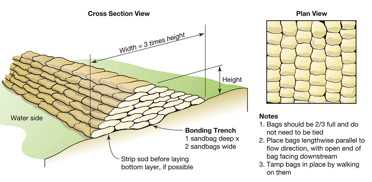
Sandbags: Temporary barriers constructed of sandbags can be used to protect structures or system components from flooding or provide additional height to existing flood barriers before flooding reaches critical levels (see figure 9). However, unless emergency placement is planned and deployed under the direction of trained personnel, most sandbag barriers are not fully effective and leaking and failure are common. Due to the intensive effort and amount of time needed for proper placement, and the limited protection they afford, sandbag walls should not be considered a reliable long-term protection measure.
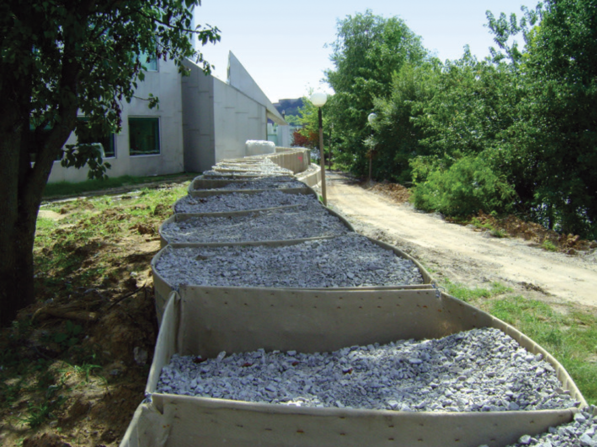
Temporary Flood Barriers: A number of vendors offer temporary, self-supporting flood barriers that can be assembled, moved into place, anchored, and filled with water, sand or gravel and then removed after flood threats have passed (see photo 4). These barriers must be sized for the site or building. Caution should be exercised when considering use of temporary barriers for flood depths greater than three feet. Training and annual drills are important, so personnel know how to deploy the barriers. Proper storage, including cleaning after deployment, is necessary to protect the materials over long periods of time.
Flood Wrapping Systems: Flood wrapping systems are temporary emergency measures in which plastic or other synthetic waterproof sheeting material is used to seal buildings and prevent water intrusion into the building and associated systems. Depending on building configuration, the use of a wrapping system may be effective to protect an equipment or machine room from frequent flooding.
The appropriate mitigation action for any part of the utility systems that serve buildings depends on whether a building is new construction, substantial improvement, or a repair of substantial damage, in which case compliance is required. If compliance or conformance is not required, some mitigation actions may reduce vulnerability to flooding damage. Other factors must be considered in the context of a specific building’s characteristics, such as whether action must be taken when flooding threatens (active or passive measures), the degree of protection required or desired and the relative cost.
Online Access to the FEMA Map Service Center
The FEMA Flood Map Service Center (MSC) is the official public source for flood hazard information produced in support of the NFIP. Use of the MSC enables owners, engineers, architects, builders, and government officials to find official flood maps, access a range of other flood hazard products, and take advantage of tools to more clearly understand the flood risk for specific structures and sites. The MSC can be accessed at http://msc.fema.gov/portal. Technical support is available at 1-877-FEMA-MAP or 1-877-336-2627 from 8:00 AM to 6:30 PM, Eastern Time, Monday through Friday.
References
- NWS (National Weather Service). 2015. National Oceanic and Atmospheric Administration’s Hydrologic Information – Flood Loss Data. Available at http://www.nws.noaa.gov/hic/.
- U.S. Global Change Research Program. 2014. Third National Climate Assessment: Climate Change Impacts in the United States. Available at http://nca2014.globalchange.gov/.
Extracted from FEMA P-348, Edition 2 / February 2017. Protecting Building Utility Systems from Flood Damage.