
Many industrial processes use electrically powered heat trace systems. Installers with little experience in this application think that heat trace cable is used to keep water pipes from freezing, but this is just the beginning. Heat trace is also used extensively to keep product being transferred from one process to another through piping at a constant temperature. This helps to keep the material liquid, or at least the same viscosity, during the transfer. Allowing the product to cool even slightly can cause unwanted chemical reactions.
There are other ways to accomplish the same task. Commonly steam is injected at low pressure into a separate tube attached to the pipe, which needs to stay at a constant temperature. Heated air can be used to perform the required function in certain applications where electrically heated cable or steam trace may be dangerous or impractical. Installation is quite expensive in both forced air and steam heat.
Electrically operated heat trace cable has a number of advantages over these other methods:
- Electrical circuits can be extended for extremely long distances without much degradation, whereas steam or heated forced air cools rapidly as it travels away from the source.
- Cable for heat trace can be installed by most qualified electricians.
- Steam systems require expert pipe fitters using a great deal of planning and time. Forced air systems are most effective in smaller, more confined areas. They also require ducting, a heat source (gas, fuel, or electric) and electric power to operate the fans at each point.
- Cable is more flexible, allowing for changes in ambient temperature to affect the installation to a smaller degree, without the need for pipe expansion joints as would be needed with steam systems.
The primary purpose of monitoring electric heat trace cable is so “leaks” can be detected before they cause irreparable harm. If steam or heated air leaks from a pipe, there may be some damage caused by excessive heat pressure or corrosion, but leaking electricity has the potential (no pun intended) to kill. A maintenance person wearing gloves and boots will be relatively well protected against shock, but it is certainly not worth taking any chances.
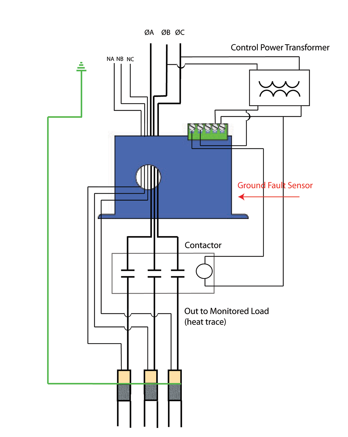
The most common installations use a cable connecting one phase to neutral, or one phase to another phase. If both current-carrying conductors pass through a ground fault sensor, the magnetic field produced by the AC current in one conductor will be canceled out by the return current in the other conductor. Over time when the cable insulation begins to break down or is damaged, and the conductor is exposed, there will be some current passing to ground, which will be detected by the sensor. When this current imbalance occurs, the ground fault sensor will open a contact to de-energize the operating coil of the contactor supplying the cable power, as shown in figure 1, or to complete a circuit to operate a shunt trip breaker operating solenoid to open the offending circuit.
In the oil fields on the North Slope in Alaska, miles and miles of heat trace cable ensure the crude stays liquefied in subfreezing temperatures. There are ground fault sensors placed in a zonal pattern, so when there is a fault it can be isolated to some degree. In this application, the contact is not used to disconnect the load from the supply. What the sensor provides is a contact closing and latching closed. This triggers an alarm, letting the system operator know that there is a problem. Since there is little chance that low-level leakage current will cause harm to humans, the fault is noted. When the opportunity arises, repair crews will move out and find the faulty cable, repair, or replace it. In the interim, the low-level current will just waste electricity; the heating effect will be diminished but not eliminated, although there may be minor damage to the pipe.
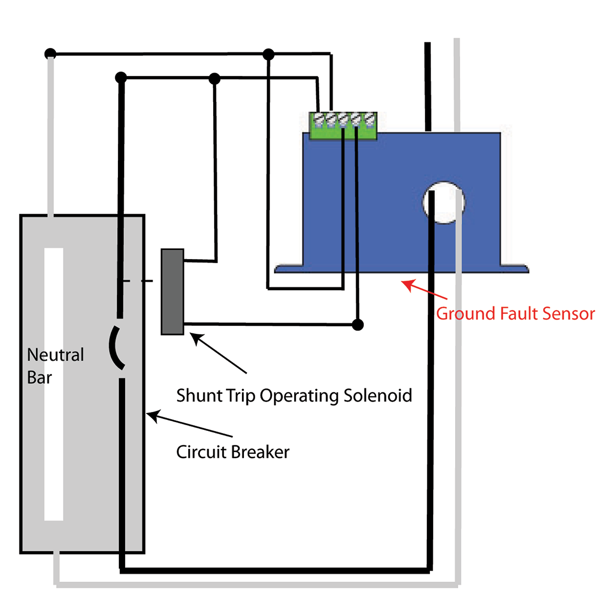
In other systems, the sensor will close a contact, which then energizes a shunt trip breaker operating solenoid, shutting off the power (see figure 2).
The National Electric Code (NEC) and Canadian Electrical Code (CEC) require that most heating loads be disconnected from the supply when ground or earth faults occur, which may damage equipment. This will keep the risk of fire from arcing to a minimum. The amount of current that will flow to ground before the sensor disconnects the load from the supply is not well defined in any place in the NEC. Relying on the circuit overcurrent will protect the wire feeding the load but not the equipment if the leakage current to earth is lower than the circuit protection level. A two-inch block of carbon steel will begin to glow when it is conducting about 500 mA. To avoid damage, the ground fault protection should be lower than 500 mA.
NEC Section 427.22 states that each branch circuit supplying electric heat equipment shall have “ground-fault protection of equipment,” with exceptions. The main exception is that in industrial environments, continued operation of the heating equipment is necessary for safe operation of equipment or processes. In these cases, the circuit need not be disconnected from the supply, but an alarm shall be required.
The manufacturers of circuit breakers have standardized the trip point of 30 mA for GFCI equipment protection. This works in most installations, but there are many applications where this may be too low to alleviate nuisance or spurious tripping. With some sensor designs, the trip point can be set at 5, 10 or 30 mA. It is much more common for system engineers to order the ground fault sensor with a single trip point set to detect any fault over 30 mA. If they have problems keeping the heat trace online or there are too many alarms, the trip point can be adjusted to a higher level, up to 100 mA in some models, and up to 950 mA in others.
Some installations are designed so the sensor contact operates in a “fail-safe” mode. Here the sensor operates the output contact as soon as the power supply energizes the sensor. These models will then have a reverse contact action when the fault current exceeds the trip point, or if the power supply is lost. A detailed examination of the control circuit is recommended.
Imagine this scenario: An auto-reset ground fault sensor trips due to a fault over the trip point, thereby de-energizing the offending load. This removes the fault current and causes the sensor to return to the untripped condition. If this contact action again re-energizes the load, and the fault is still present, the sensor will trip again, setting up a cycle of frustration for the user.
Melting snow from sidewalks, driveways, and roof gutters use similar heating methods in residential and industrial applications. Ground-fault protection (GFP) of equipment shall be provided for fixed outdoor electric deicing and snow-melting equipment as referenced at 426.28. While many of these systems can be protected by GFCI outlets or circuit breakers when the current needed to operate exceeds 20 amps or the circuit potential is higher than 125 VAC, using a sensor coupled with a shunt trip breaker or contactor can be a solution. The reaction time of the sensor is not as critical as when personnel must be protected, but the sooner the faulting circuit can be disconnected the less chance for damage to the cables or heating mats.