
What is fault current? What is short-circuit current? The answer is the same for both questions, because they are two different ways of saying the same thing. Both terms are used to identify the amount of current that will flow during a short-circuit condition. In the 2017 National Electrical Code® (NEC®), both terms are used, but neither are defined. Because of this, these questions were recently addressed during the 2020 NEC Code cycle. This was done by creating a task group, and they decided that the proper term to use is fault current and submitted public inputs to add definitions and revise sections to use the term “fault current” for consistency. This article discusses the new definitions, how to determine the amount of fault current, and applicable NEC requirements.
Fault Current
As discussed previously, fault current and short-circuit current are interchangeable; they both indicate the current that can flow at a point on the system during a short-circuit condition. This amount of fault current varies based upon the source of power and where the short-circuit condition is created. Therefore, another term, available fault current, was needed. This is the maximum amount of current that can be delivered at a specific point in the system during a short-circuit condition. The important thing to remember is that fault current and available fault current are related to the electrical system parameters.
The 2020 NEC has newly added definitions for “fault current” and “available fault current” in Article 100 per below:
Fault Current. The current delivered at a point on the system during a short-circuit condition.
Fault Current, Available (Available Fault Current). The largest amount of current capable of being delivered at a point on the system during a short-circuit condition.
Informational Note: A short-circuit can occur during abnormal conditions such as a fault between circuit conductors or a ground fault. See Informational Note Figure 100.1.1 [See figure 1]
The figure referenced in the information note also indicates the importance of the terms “interrupting rating,” which applies to overcurrent protective devices, and “short-circuit current rating,” which applies to equipment.

Calculating Available Fault Current
When calculating the available fault current, the starting point is always the source of power, which is typically the utility. The utility may provide the amount of fault current at the service point or a simple calculation based upon the transformer supplying the service can be used.
Once this value is determined, the next step is to do another calculation based upon the conductors or busway from the service point to the service entrance equipment.
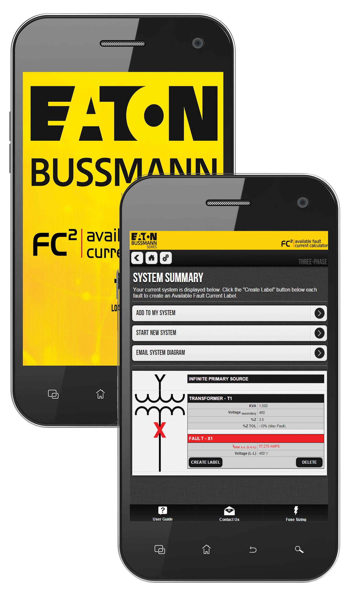
This process is then repeated for equipment downstream of the service entrance equipment. This calculation can be done by hand, by software programs or by mobile applications, such as the Eaton Bussmann series mobile app, FC2.
Documentation/Marking of Available Fault Current
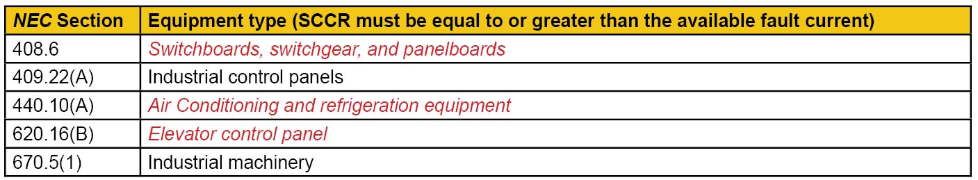
Since the 2011 NEC, it has been required to mark the available fault current at service entrance equipment. In the 2017 NEC, it is now required to either document and/or mark the available fault current at the equipment shown in red shown below.
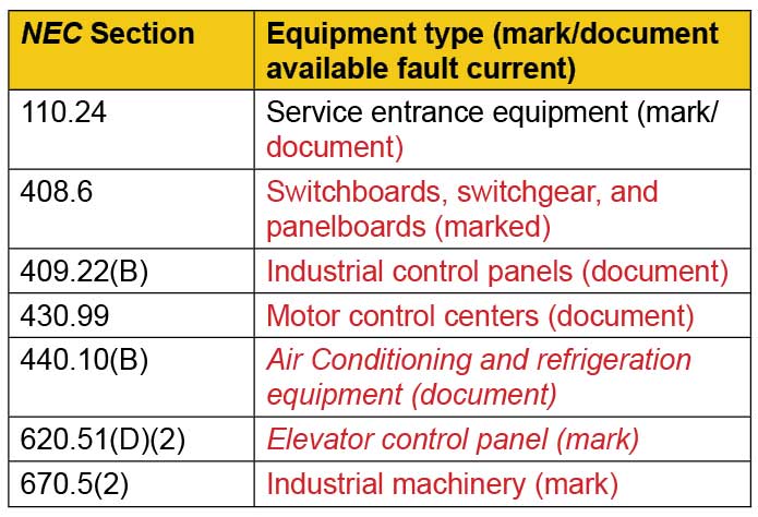
The 2020 NEC added a new requirement in Section 408.6 for panelboards, switchboards, and switchgear that requires field marking of the available fault current in other than one- and two-family dwelling units. This is a significant change requiring nearly all electrical power distribution equipment to be marked with the available fault current.
Interrupting Rating and Overcurrent Protective Device Requirements
The first term that was used in the NEC to identify an overcurrent protective device’s ability to interrupt current was “interrupting capacity.” Circuit breaker manufacturers then, and in some cases today, used the acronym “AIC,” which is short for “ampere interrupting capacity.”
This term, and the requirement that overcurrent protective devices must have adequate interrupting capacity, dates to the 1940 NEC, where Section 1109 stated, “Devices intended to break current shall have an interrupting capacity sufficient for the voltage employed and for the current which must be interrupted.”
The 1959 NEC changed this from Section 1109 to 110-9. In the 1978 NEC the term interrupting capacity was changed to interrupting rating and a second paragraph was added to NEC 110-9 that identified equipment other than fault levels must have an adequate interrupting rating as well, such as devices that are required to interrupt overloads. In 1981, the definition of interrupting rating was added. The current definition of interrupting rating in NEC Article 100 and the current text of NEC 110.9 is shown below.
110.9 Interrupting Rating. Equipment intended to interrupt current at fault levels shall have an interrupting rating at nominal circuit voltage at least equal to the current that is available at the line terminals of the equipment.
Equipment intended to interrupt current at other than fault levels shall have an interrupting rating at nominal circuit voltage at least equal to the current that must be interrupted. 1
So, since the 1940s, the question that should have been asked is — “What is the highest amount of current (available fault current) that the overcurrent protective device must be capable of interrupting and what is the corresponding interrupting rating (interrupting capacity) that the overcurrent protective device must have?”
Short-Circuit Current Ratings and Equipment Requirements
The counterpart to the interrupting rating of overcurrent protective devices is the short-circuit current ratings of equipment. The term used previously, but not defined in the NEC, was the “short-circuit withstand rating,” and it simply referred to the highest amount of current the equipment could safely withstand. In the 2005 NEC, the definition of short-circuit current rating (SCCR) was added as shown below.
Short-Circuit Current Rating. The prospective symmetrical fault current at a nominal voltage to which an apparatus or system is able to be connected without sustaining damage exceeding defined acceptance criteria.1
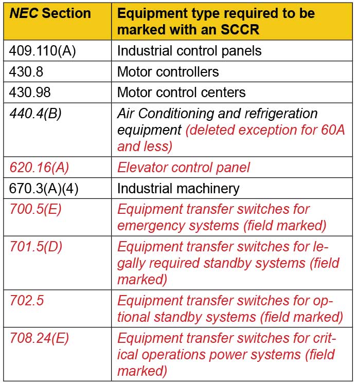
Also in the 2005 NEC, additional equipment, that was often overlooked, was required to be marked with a SCCR (shown in black text in table 2). In the 2017 NEC, additional equipment was required to be marked with a SCCR (shown in red text in table 2). The driving force for adding the marking requirements of SCCR is to ensure the equipment is not installed at locations where the available fault current is higher than its marked SCCR, thus preventing a serious safety hazard. Note that marking for transfer switches is a field marking in addition to the manufacturer marking. The field marking is needed since the SCCR of the transfer switch can vary based upon the upstream overcurrent protective device type, rating, and settings.
Similar to NEC 110.9 for proper application of interrupting rating, NEC 110.10 requires equipment to have a short-circuit current rating adequate for the available fault current. NEC 110.10 has been in the NEC since 1965 and requires the protection of electrical components from extensive damage. The 1978 version of NEC 110.10 added the term short-circuit withstand rating. In the 1999 NEC, this term was changed in NEC 110.10 to “short-circuit current rating.” So, since 1965, the question that should have been asked is — “What is the available fault current and what are the electrical component (equipment) ratings (short-circuit current ratings)?” When applying electrical equipment such as switchboards, panelboards, motor control centers, disconnect switches, automatic transfer switches and other equipment as required per the current version of the NEC.
110.10 Circuit Impedance, Short-Circuit Current Ratings, and Other Characteristics. The overcurrent protective devices, the total impedance, the equipment short-circuit current ratings, and other characteristics of the circuit to be protected shall be selected and coordinated to permit the circuit protective devices used to clear a fault to do so without extensive damage to the electrical equipment of the circuit. This fault shall be assumed to be either between two or more of the circuit conductors or between any circuit conductor and the equipment grounding conductor(s) permitted in 250.118. Listed equipment applied in accordance with their listing shall be considered to meet the requirements of this section. 1
Looking at the wording of NEC 110.10, it may be confusing that this requirement is simply requiring the equipment SCCR to be adequate for the available fault current.
- For instance, why does it reference the overcurrent protective devices? This is because equipment SCCR may be dependent upon a specific overcurrent protective device.
- Why does it reference the total impedance? This is because the available fault current varies based on where in the system the equipment is located (the total impedance from the power source to the point of the short-circuit condition).
- What are the other characteristics to consider? These might be something like minimum enclosure size for a given component in the equipment.
- What is “extensive damage?” This indicates that damage may occur, but it must not present a shock hazard, fire hazard, or expel projectiles from the equipment.
- If equipment is Listed, do I have to worry about SCCR? Yes, you do. This refers to the fact that NEC3(B) requires applying equipment per its listing and labeling. Hence, if the equipment SCCR is 5kA, it would be a violation of NEC 110.3(B) and NEC 110.10 if the available fault current was greater than 5kA.
In the 2011 NEC, additional requirements were added that clearly indicate the equipment SCCR must be equal to or greater than the available fault current for industrial control panels and industrial machinery electrical panels and equipment. In the 2017 NEC, similar requirements were added for the equipment shown in red below. Again, the important thing to remember is the short-circuit current rating relates to “equipment,” and the equipment SCCR must be equal to or greater than the available fault current.
In the 2020 NEC, the new Section 408.6 not only requires the field marking of all switchboards, switchgear, and panelboards, but also requires that the SCCR be equal to or greater than the available fault current. This requirement is not really “new” because the equipment has been required to meet 110.9 and 110.10 for many Code cycles. It does serve to highlight the need to evaluate this equipment for proper SCCR to engineers, contractors, and inspectors. It can still be challenging to evaluate and inspect this equipment for proper SCCR because typical circuit breaker panelboards and switchboards will accept numerous different circuit breakers, and the SCCR is dependent on the lowest interrupting rating device installed in the equipment. Therefore, it is important for engineers and contractors to note the specific circuit breakers and their interrupting ratings so that the inspectors can easily evaluate the equipment for proper SCCR.
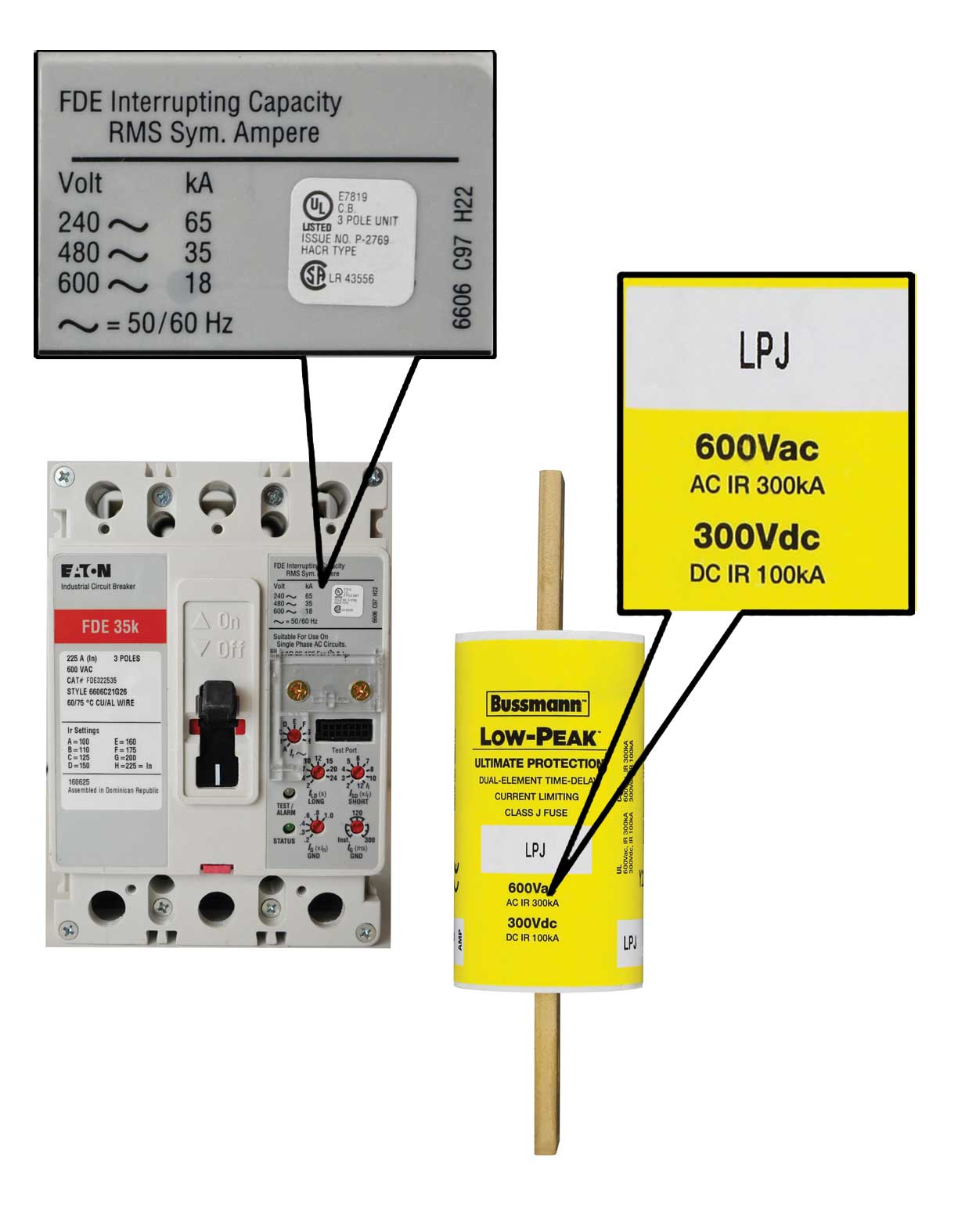
It is also important to install circuit breakers with proper interrupting rating when replacing or adding new circuit breakers after the initial installation. If series ratings are used, the series rating must be verified for compliance with 240.86 and marked in accordance with 110.22(B) or (C). Typical fusible equipment will have a 100,000-ampere or 200,000-ampere SCCR when using current-limiting fuses such as Class CF, J, R, L or T. Care should be taken to install rejection style clips in equipment that can accommodate Class R fuses, but reject Class H (K5) fuses as required per 240.60(B) on systems capable of delivering more than 10,000-ampere of fault current. The use of Class H switches will allow the use of non-current limiting Class H fuses and limits the assembly SCCR to 10,000-amperes.
Selective Coordination
The available fault current is also a key consideration for critical systems where selective coordination is required or desired. This is because the definition of selective coordination, which was modified in the 2014 NEC, now clearly indicates that this includes the full range of overcurrents (all currents), from overload to the available fault current, and the full range of overcurrent protective device opening times (all times).
Coordination, Selective (Selective Coordination). Localization of an overcurrent condition to restrict outages to the circuit or equipment affected, accomplished by the selection and installation of overcurrent protective devices and their ratings or settings for the full range of available overcurrents, from overload to the maximum available fault current, and for the full range of overcurrent protective device opening times associated with those overcurrents. 1
The underlined text above was added since some mistakenly interpreted selective coordination to be “time-based.” This was not the intent, so selective coordination is not for 0.1 seconds or 0.01 seconds, but essentially down to time “zero.” Despite this change to the definition, this misunderstanding of limiting the time to 0.1 seconds or 0.01 seconds continues to be promoted. In fact, one manufacturer stated, “total selective coordination (some in the industry refer to this as selectivity down to 0.01 seconds).” This is not a true statement.
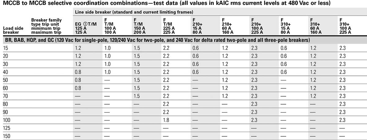
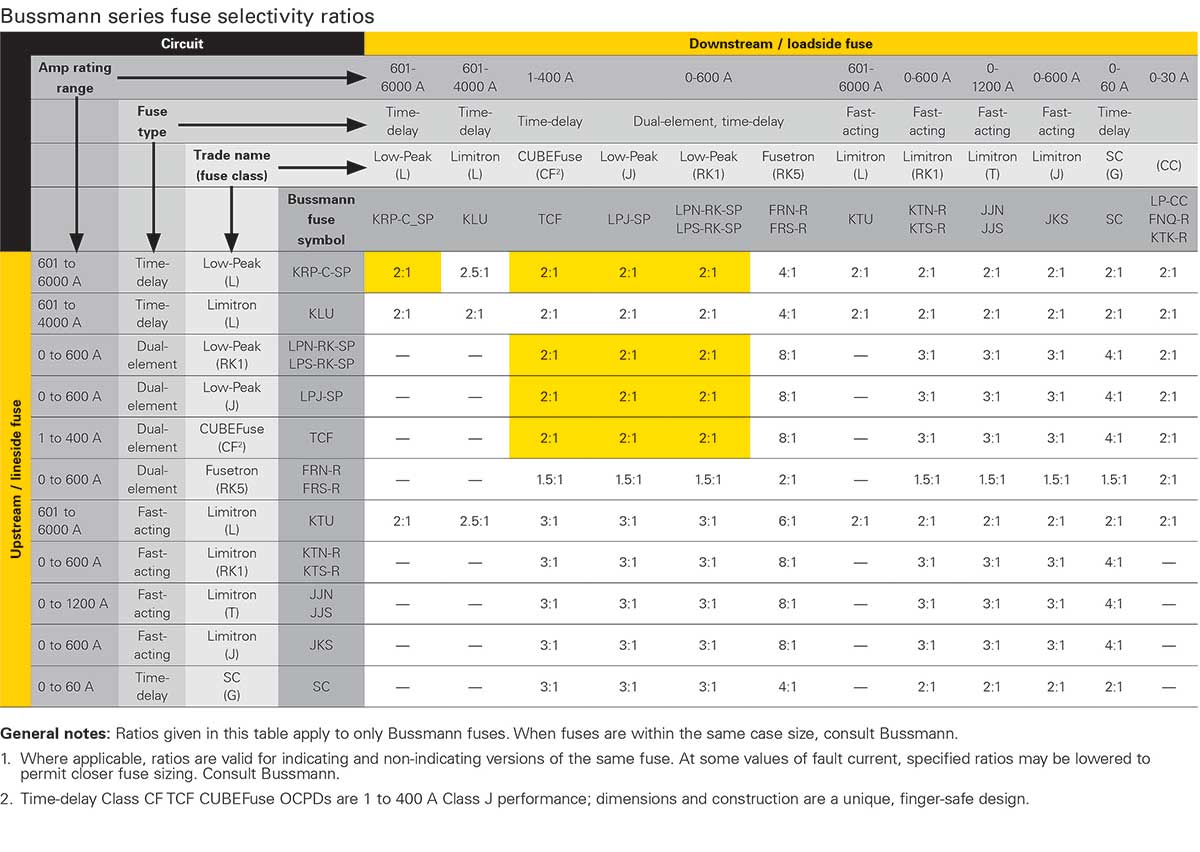
To analyze for all overcurrents and all times, analysis of only time-current curves, in most cases, is not sufficient when evaluating overcurrent protective devices for selective coordination. Under certain conditions, confirmation of all currents and all times may require the use of manufacturer selective coordination tables, as shown in figure 4 for fuses and circuit breakers. For circuit breakers, the table shows the maximum fault current for which a pair of circuit breakers are selectively coordinated. Fault currents above this value will result in a lack of selective coordination. As you can see in figure 4, circuit breakers are often only capable of achieving selective coordination for lower levels of available fault currents.
To achieve selective coordination at higher fault currents, the upstream circuit breaker may need to be increased in ampere rating and may require additional capabilities such as short-time delay plus the conductors may need to be increased in ampacity.
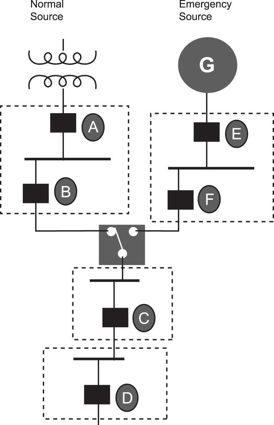
An important change was made in the 2020 NEC with regards to clarifying which overcurrent protective devices must have selective coordination. An informational note and figure was added to 700.32, 701.32, and 708.54 to address this concern. This note clarifies the emergency system overcurrent devices (on the load side of the automatic transfer switch) must selectively coordinate with the normal source overcurrent protective devices. However, the overcurrent protective devices that are not emergency system overcurrent protective devices (normal source overcurrent protective devices) are not required to be selectively coordinated with other non-emergency OCPDs.
700.32 Selective Coordination. Emergency system(s) overcurrent devices shall be selectively coordinated with all supply-side overcurrent protective devices.
Selective coordination shall be selected by a licensed professional engineer or other qualified persons engaged primarily in the design, installation, or maintenance of electrical systems. The selection shall be documented and made available to those authorized to design, install, inspect, maintain, and operate the system.
Exception: Selective coordination shall not be required between two overcurrent devices located in series if no loads are connected in parallel with the downstream device.
Informational Note: See Informational Note Figure 700.32 for an example of how emergency system overcurrent protective devices (OCPDs) selectively coordinate with all supply-side OCPDs.
OCPD D selectively coordinates with OCPDs C, F, E, B, and A.
OCPD C selectively coordinates with OCPDs F, E, B, and A.
OCPD F selectively coordinates with OCPD E.
OCPD B is not required to selectively coordinate with OCPD A because OCPD B is not an emergency system OCPD.1
Summary
Fault current and available fault current are key considerations for the proper application of overcurrent devices, equipment, and systems where selective coordination is required. The 2020 NEC definition of “fault current” and “available fault current,” as well as the informational note and figure in the definition of available fault current help explain the importance of overcurrent protective device interrupting rating and equipment short-circuit current ratings as it relates to the system available fault current. Proper application of overcurrent protective device interrupting rating and component and equipment SCCR should not be a new concept as the history dates back to 1940 and 1965 respectively. Because of the changes related to this topic since the 2005 NEC, don’t be surprised when the electrical inspector asks you these questions — “What is the available fault current? Is it marked or documented? And are the overcurrent protective devices and equipment short-circuit current ratings equal to or greater than the available fault current?”
References
- NFPA 70®, National Electrical Code®, 2020 edition. Copyright© 2019, National Fire Protection Association. For a full copy of NFPA 70®, please go to www.nfpa.org.