Photovoltaic (PV) power systems are fairly rugged electrical systems when properly designed and installed. They will operate unintended with little or no maintenance for many years, possibly decades, while producing significant amounts of electrical energy. The durable nature of PV systems demands that the design and installation be of the highest quality in order to achieve this longevity. And, it behooves the electrical inspector to ensure that the installation meets Code requirements in all aspects. Considering the complexity of the PV systems and the environment in which they operate, that is no easy task for the AHJ. In this article we will examine a few of the details that are sometimes overlooked in the inspection of a PV system.
The Environment
With a salute to the US Postal Service: Neither snow nor rain nor heat nor gloom of night stays the PV system from producing power. Well, OK, the PV system will stop producing power at night and will have reduced output when the sun is not shining brightly, but when the sun next comes up, it will be ready to produce the rated power, or more, day after day and year after year.
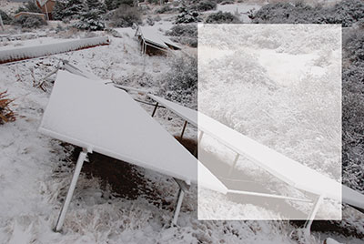
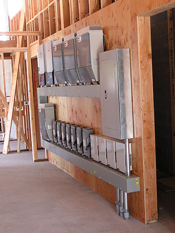
The environment that the PV array operates in is harsh. The array and the module and string wiring are exposed to outdoor environmental conditions from the coldest temperatures in the winter to the hottest temperatures in the summer plus the added stress of high winds, sleet, hail, snow, and nearly every day additional heating due to solar radiation. See the lead-in photo.
The PV system may be subjected to high levels of sunshine (irradiance) on a continuous basis (three hours or more) when the sky is clear, the sun is bright, and there is low atmospheric pollution (humidity, dust, smog, etc.). Under those conditions, the PV array may produce power and current that can reach 125% of the rated output. The PV system is designed to accommodate these situations. The PV system will also be subjected to short periods (minutes) of cloud enhanced, snow enhanced or water enhanced irradiance that can be up to 150% of the bright, sunny day sunshine.
These environmental factors and the fact that this is an electrical power system that produces power in a daily cycle means that all of the conductors, any combiners, all overcurrent devices and disconnects, and each and every electrical terminal is subjected to a cyclic flow of current from zero at night to a maximum at or above (for short periods) the rated value of the device every day. Additionally, the environmental heating and cooling variations on a daily and a seasonal cycle impose additional stresses on the PV system.
This high stress environment and operation is somewhat unique compared to the typical residential and small commercial electrical systems that are familiar to the AHJ. And, when we look at the fact that these systems may operate unattended and unmaintained for years, if not decades, it demands that the highest quality designs, materials, equipment, and installation be associated with photovoltaic power systems. The AHJ in the plan review and final inspection of a PV system has the final responsibility and authority to verify that the stringent requirements of the electrical and building codes are followed in the installation. Let’s look at some details in various PV subsystems that may need additional attention in order to achieve a hazard-free, long-lived system.
Yes, Time and Money Are in Short Supply
It is acknowledged that many residential electrical systems are inspected in less than an hour. That is probably acceptable for an electrical system that has remained essentially unchanged for 100 years, where the inspector is quite familiar with the Code requirements for those electrical systems and is also familiar with the technologies and equipment being installed. Experience with the contractors involved also speeds the inspection process.
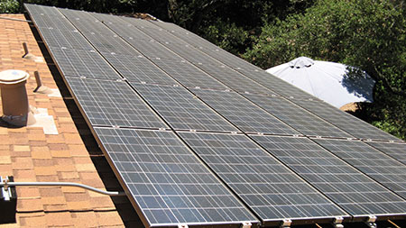
It is also acknowledged that many jurisdictions do not have plan review and unfortunately this hampers the ability of the inspector to verify easily all of the Code requirements. PV modules on the roofs are generally mounted close to the roof and it is generally not possible to examine all of the connections in the PV array including conductor size, grounding and bonding, and module wiring interconnections (photo 1). In a related issue, in a well-installed PV or other electrical system, it is sometimes difficult to verify conductor types and conductor sizes where connections are made inside of the standard disconnecting devices and inverters. These particular code requirements are best reviewed in a plan review stage even if that review is only a half an hour in the office looking at the detailed schematics and diagrams that were submitted with the permit application. If issues are found during the office review, it is almost certain that similar issues or more critical ones will be found if time is taken to examine those particular areas in the field inspection.
While many of the larger PV systems are ground mounted, the great majority of residential PV systems and smaller commercial PV systems are mounted on the roofs of buildings. And, unfortunately, some jurisdictions have insurance policies that prohibit the inspector from going on the roof, making an examination of those critical components in the PV system impossible. If a ladder is available– and the installing contractor should make all areas of the array easily accessible by providing ladders–the inspector might be able to view some of the array from the ladder without actually going on to the roof. And the roof is no place to be in inclement weather.
The Array
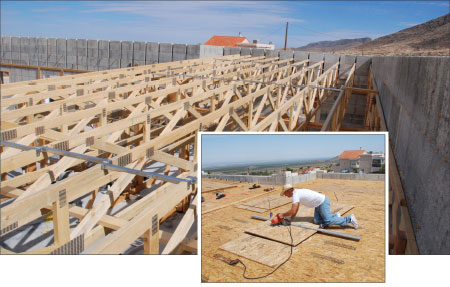
Combination inspectors who are also building inspectors are probably more aware of the mechanical requirements to fasten the PV modules to the roof and the building structure than the typical electrical inspector might be. Most mounting systems including PV racking systems require that the PV array be connected to the structural elements of the roof and not just to the thin roof sheathing. Without going into the attic (and the flat roofed Southwest homes have no attic) it is difficult to verify that the mechanical fasteners are indeed being inserted into the structural roofing components. See photo 2. A standard spacing for trusses in many parts the country is 24 inches with older homes having structural members at 16 inches. A quick check of the exterior mounting feet for the array rack should show them to be consistently on some multiple of these dimensions. Racking and mounting systems are continually evolving and any system must be installed according to the manufacturer’s instructions.
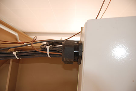
The module interconnect wiring should be firmly secured to the racking members or otherwise supported. See the March-April 2015 issue of the IAEI magazine for an excellent article by Bill Brooks and Jim Rogers on cable support systems. Those exposed, single-conductor cables should not be hanging loosely below the modules where they are subjected to additional mechanical stress from wind loading and the possibility of abrading the insulation against the roof. Unfortunately, many of the plastic wire ties that are frequently used to attach these conductors to the racking members, although listed for outdoor exposure, do not have the necessary longevity for the years of service needed in a PV system (photo 3). It is suggested that metal clips with rounded edges be used to attach these wires to provide the longevity needed for a PV system.
Module connectors should be firmly seated and to some extent that can be visually evaluated at a distance, but where the conductors have been properly secured to the racks, the connectors may be less visible.
The grounding and bonding methods used for the modules and the racks should be evaluated and compared with the instructions for those devices.
Can’t get on the roof?
In those jurisdictions where it is not possible for the AHJ to get to the roof to examine the aforementioned parts of the array closely, it is possible to query the installer about some of the things mentioned above. For example, the method of grounding and bonding the modules and the racks can be discussed while looking at the instructions for those pieces of equipment. It might be a good idea to ask the installer to see the torque wrenches and torque screwdrivers that are necessary to properly install those grounding and bonding devices. The ties or clips used to attach and secure the module wiring to the racking members could be discussed along with any listing or other information that addresses the durability of those particular devices in the PV application. The installer might be queried on the method of determining where the racking or module attachment devices were located in relation to the structural members of the roof.
Torquing Considerations
All electrical connections that require a threaded fastening will have a torque requirement for making that connection correctly. These threaded screw or bolt connections are found on disconnect switches, overcurrent devices, DC combiners, and inverter inputs and outputs. Due to the daily cycling of the currents in these circuits, it is critical that they be torqued to the manufacturer’s specifications. The installer should be able to provide data on all of those torque specifications. The torque values that should have been used should be readily available in the manuals and cut sheets provided with the permit application (photo 4).
See the informative article by Rhonda Parkhurst on inspecting these types of connections for proper torque in the January-February 2015 IAEI magazine. Ask the installer to show you the torque wrenches and torque screwdrivers used to make these connections. It’s not a bad idea, where it can be done safely, to pull on a few conductors attached to these terminals to see if they have been tightened at all. Ah, you might think this is extreme, but conductors have been pulled loose from breakers by inspectors where they we never tightened—just like plumbing inspectors who find drain traps loose and leaking when inspecting new homes. Also the torque tools can be used to verify that the minimum value of torque has been achieved, but obviously no torque test should be done on energized circuits.
The AC Utility Connection
Although Section 705.12 of the NEC is being improved in each edition of the Code, the requirements still confuse some installers and some AHJs. Here are a few simple checks that can be done in the field to at least partially verify Code compliance.
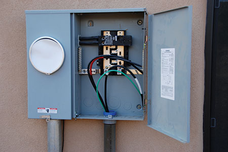
A supply-side connection as allowed by 705.12(A) will be made between the existing revenue meter and the main disconnect on the service. This connection is typically not allowed to be inside a meter-main combo load center where tapping either the internal conductors or the bus bar between the meter socket and the main disconnect would violate the listing on the load center (photo 5).
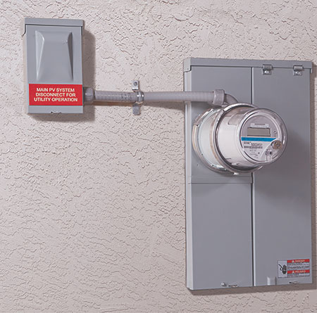
There are now several listed meter socket adapters on the market designed for making a supply side connection at the meter. The existing meter is removed, the adapter is installed in the existing meter base socket, and the meter is reinstalled by plugging it into the adapter. The adapter provides a set of terminals that are a supply-side connection. This adapter might conceivably even be used in a meter main combo load center to make a utility connection without violating the listing on the load center. While this is a listed device, usually utility approval is required for its use since many utilities consider the meter and the meter base to be under utility control (photo 6).
The rating of a supply-side connection for a PV system is limited by the size of the service entrance or any meter adapter or conductors involved with the service. A 100 amp service entrance that has 100 amp meter and 100 amp service entrance conductors could be fed by a 100 amp PV overcurrent device. If a meter adapter were used it would also have to be rated at 100 amp to utilize the full 100 amp from a PV system.
Load side connections, under 705.12(D), are made by backfeeding a circuit breaker in the main load center or making a connection elsewhere in the electrical system at a subpanel or possibly even tapping a feeder. Although 705.12(D) has been clarified significantly in the 2014 NEC, there are still a number of considerations to be made that are best checked in the office in a plan review exercise. However, the most common connection is a backfed breaker in the main load center and several items are relatively easy to verify for code compliance.
In order to use the 120% rule, the backfed breaker must be located in the load center as far as possible from the main breaker. Main breaker at the top of the panel? Then the backfed PV breaker must be in the last position at the bottom of the busbar. If the backfed breaker is in this position, then the 120% rule can be applied and normally, with a main breaker rated the same as the bus bar for the load center, the backfed breaker can be up to 20% of the rating of the load center.
When the main breaker is less than the rating of the load center, there is a simple method of calculating the maximum allowable rating of the PV backfed breaker. The PV backfed breaker can be no greater than 120% of the busbar rating minus the main breaker rating. And, the 2014 NEC complicates or simplifies the situation (depending on your point of view) by allowing 125% of the rated inverter current to be used rather than the actual rating of the backfed circuit breaker in these calculations.
Where the backfed PV breaker is not located at the bottom of the busbar opposite the main breaker, the 120% rule cannot be used. If the main breaker is rated the same as the busbar, then no backfed PV breaker can be installed. In some cases, the main breaker may have been reduced in size where justified by full NEC Chapter 2 load calculations, and then the difference between the main breaker rating and the busbar rating would be the allowable rating for the backfed PV breaker.
Summary
There are numerous details involved in the installation and inspection of PV systems. If some of these details have been overlooked or not properly addressed by the installer, it is very likely that additional areas of the PV system are not in compliance with requirements the National Electric Code. With new installers, new and unusual electrical equipment, and the outdoor environmental conditions involved with the PV system, it is generally going to take more than a short inspection of a typical residential or small commercial PV system. Detailed schematics and manuals should be submitted with any PV permit application. If at all possible some sort of plan review should be carried out in the office to verify that the basic design of the PV system meets Code requirements.
For More Information
The author has retired from the Southwest Technology Development Institute at New Mexico State University, but is devoting about 25% of his time to PV activities in order to keep involved in writing these “Perspectives on PV’ articles in the IAEI News and to stay active in the NEC and UL Standards development process. Seven to eight hour presentations are still available on PV and the Code and they cover 2008-2014 NEC requirements. He can be reached at: e-mail: jwiles@nmsu.edu, phone: 575-646-6105
The Southwest Technology Development Institute web site maintains a PV Systems Inspector/Installer Checklist and all copies of the previous “Perspectives on PV” articles for easy downloading. A color copy of the latest version (1.93) of the 150-page, Photovoltaic Power Systems and the 2005 National Electrical Code: Suggested Practices, written by the author, may be downloaded from this web site: http://www.nmsu.edu/~tdi/Photovoltaics/Codes-Stds/Codes-Stds.html.