Practical Example
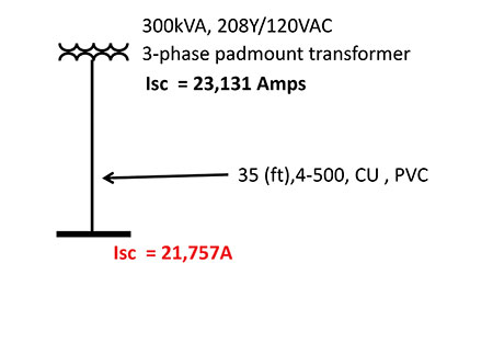
The following is a real-life example of a church supplied from a 208Y/120 VAC, 300 KVA, 3-phase pad mount utility transformer. The published utility tables indicate the available short-circuit current at the secondary terminals of the transformer to be 23,131 amperes. The service lateral consists of four sets of 500 KCMIL, CU conductors 35 feet in length, installed in PVC raceways to service equipment. The Bussmann Fault Current calculator is leveraged to calculate the maximum available fault current at the service entrance equipment considering the service lateral conductors. The maximum available fault current at the service equipment is calculated to be 21,757 amperes. (See figure 7.) For this example, we will need to provide a label that meets 110.16(B).
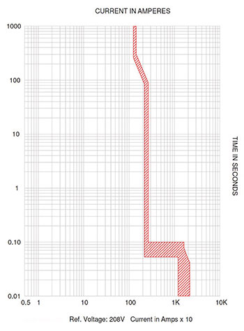
This is a 1200-amp service. The main in this panel in the field is a 1200 A molded-case circuit breaker. The manufacturer’s trip curve for this main OCPD is shown in figure 5. The curve is cut off at the fault current value of 21,757, the fault current at the panel.
Here is what we know about the clearing times for this circuit breaker based upon the trip curve:
- Any fault current greater than 16,120 amps is into the instantaneous region of this main OCPD and carries a clearing time of 0.04 Seconds (2.5 cycles)
- Any fault from 2,612 A to 16,120 amps is in the short-time delay region and has a clearing time of 0.1 seconds (6.25 cycles)
- Fault currents less than 2,612 amps are into the long-time region of this circuit breaker
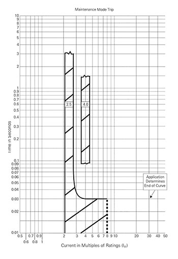
Because this is a 1200-amp circuit breaker, section 240.87 tells us that we must employ an arc reduction technology. The technology used here is the Arc Reduction Maintenance switch. From this trip curve (figure 6) we know that for fault currents greater than 3,300 amps, the clearing time of the circuit breaker is 0.03 seconds or 1.9 cycles.
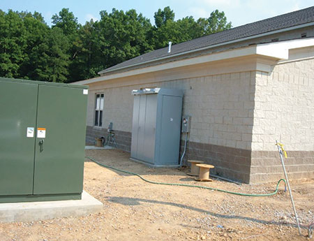
Figure 1. The church service equipment of this example.
To meet the requirements of the positive language of 110.16(B), the label would read as follows (figure 2):
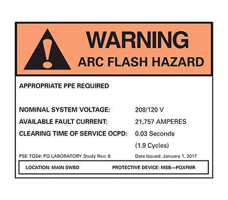
- Nominal system voltage = 208/120 volts
- Available fault current = 21,757 amperes
- Service OCPD clearing time = 0.03 seconds (1.9 cycles)
- Date: 1/1/2017
If the exception is leveraged, any one of the following two labels, per NFPA 70E, would be acceptable:
Calculated Incident energy label:
The calculation method leverages the equations found in IEEE 1584 or any other acceptable method. The basic process and input for this calculation is as follows:
1. Obtain the actual available fault current. In this case, we are given the theoretical maximum from the utility which cannot be used for the arcing current calculation. Without that information, we can only make two conservative assumptions and use the maximum calculated incident energy for our label. In this case, we will use both the maximum available fault current provided from the utility and 50% of that value for our calculations. (Reference IEEE Paper titled “Impact of Available Fault Current Variations on Arc-Flash Calculations” by Balasubramanian and Graham) Thus, the two values of fault current are:
a. ISC = 21,757 amps
b. ISC = 10,878 amps
2. Two values of arcing current are calculated per the IEEE 1584 equations for each of these available fault current values. The new Eaton Bussmann arcing fault current calculator was used to calculate these values (http://arcingcurrentcalculator.bussmann.com ); they are as follows:
a. For ISC of 21,757 amps the arcing current values could be as high as
i. Arcing Current: 7,510 A
ii. 85% Arcing Current: 6,380 A
b. For ISC of 10,878 amps the arcing current values could be as low as
i. Arcing current: 4,610 A
ii. 85% Arcing Current: 3,920 A
3. The clearing times for these arcing fault currents are obtained from the main circuit breaker trip curve. The clearing times are determined with consideration that the circuit breakers are in maintenance mode. (Note that per Section 240.87, since this is a 1200-ampere breaker an arc reduction method is required.) The clearing times are recorded as follows:
a. For ISC of 21,757 amps, the clearing times for the corresponding arcing currents could be as high as
i. For an arcing current of 7,510 A, the clear ing time is 0.03 seconds
ii. For an arcing current of 6,380 A, the clearing time is 0.03 seconds
b. For ISC of 10,878 amps the clearing times for the corresponding arcing currents could be as high as
i. For an arcing current of 4,610 A, the clearing time is 0.03 seconds
ii. For an arcing current of 3,920 A, the clearing time is 0.03 seconds
4. Armed with arcing current values and corresponding clearing times, the IEEE 1584 incident energy equations are utilized to provide the maximum incident energy for this application.
a. For an ISC of 21,757 amps, the corresponding incident energy is calculated as 0.7 Cal/cm2
b. For an ISC of 10,878 amps, the corresponding incident energy is calculated as 0.4 Cal/cm2
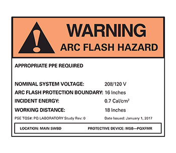
5. The label is created and reflects the worst-case incident energy from the calculations above (figure 3):
a. Nominal system voltage = 208/120 volts
b. Arc-flash protection boundary = 16 inches
c. Incident energy = 0.7 Cal/cm2 at 18 inch working distance
6. Those who would happen to perform justified energized work, including inspections within the arc-flash boundary, would review this label and wear arc-rated clothing that has a calorie rating greater than that shown on the label.
Table method
The table method can be used to provide a label as per NFPA 70E Table 130.7(C)(15)(A)(b) or to help determine proper PPE when justified energized work or inspection within the arc flash boundary is performed and the label includes the information required under the positive language of 110.16(B).
The following are the steps to determine the label or proper PPE.
- Note the voltage of the panel is 208 volts.
- The available fault current is obtained from that calculated at the service-entrance panel which is 21,757 amps. Note that this information is also printed on the label as part of the positive language of 110.16(B) and would be required as part of the steps to determine proper PPE to wear should justified energized work or inspection occur in the future.
- The clearing time of the arc reduction maintenance switch is 0.03 seconds. Note that this information, too, is printed on the label as part of the positive language of 110.16(B). This information is required as part of the steps to determine proper PPE to wear should justified energized work or inspection within the arc flash boundary occur in the future.
- Armed with this information, Table 130.7(C)(15)(A)(b) is consulted, the parameters of available short-circuit current and fault clearing time is met and the arc flash PPE category is determined to be 1 and, as per the table, the arc flash boundary is determined to be 19 inches.
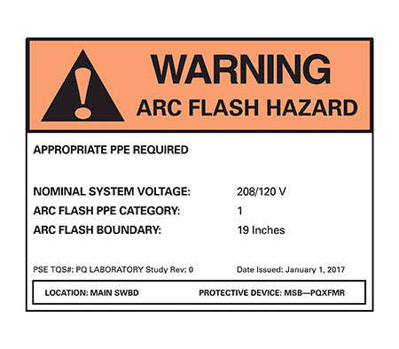
- The label to be applied to the equipment would read as follows (figure 4):
- Nominal system voltage = 208/120 volts
- Arc flash PPE category = 1
- Arc flash boundary = 19 inches
Note that the positive language of 110.16(B) provides enough information to utilize the Table method of NFPA 70E.