Electrical power is essential for the continued operation of various types of fire safety-related equipment under fire conditions. Fire safety equipment includes fire pumps, fire alarm signaling equipment, elevators, alarms and industrial process control equipment. The National Electrical Code addresses the importance of maintaining the circuit functionality by requiring protection from potential damage by fire, structural failure or operational accident in Article 695 for fire pumps, Article 700 for emergency systems and Article 760 for fire alarm systems.
There are several different types of listed fire-resistive systems that comply with specific NEC requirements detailed in Articles 695, 700 and 760. These fire-resistive systems are intended to maintain the electrical functionality of the circuits during a fire. An overview of the tests used to evaluate the fire-resistive performance of the systems will be provided as well as the different characteristics provided by each type of protective system.
Fire characteristics such as flammability and smoke generation of the materials used in these systems are not addressed in this article.
Article 695, Fire Pumps
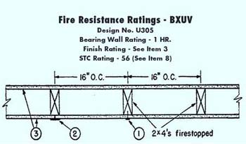
Figure 1. Fire resistance ratings – BXUV
Section 695.6(B) details the requirements for fire pump supply circuit conductors on the load side of the final disconnecting means and overcurrent device to be routed through a building. The NEC identifies the following three methods that can be used to provide protection to the circuit:
1. Encased in a minimum 50 mm (2 in.) of concrete
2. Located within an enclosed construction dedicated to the fire pump circuit(s) and having a minimum of a 1-hr fire-resistive rating
3. Have a listed electrical circuit protective system with a minimum 1-hour fire rating.
As an alternative to method 1, requiring the conductors being encased in 50 mm (2 in.) of concrete, Section 695.6(B) permits methods 2 and 3 for which there are listed systems.
Fire-resistive constructions specified in method 2 include many forms of construction. What is significant to note is that the entire wall assembly or floor-ceiling assembly is rated and not a component of the assembly such as a ceiling membrane or a layer of gypsum board. The fire test method used to establish these fire-resistive ratings for building assemblies is defined in the Standard for Fire Tests of Building Construction and Materials, UL 263, as well as ASTM E119 and NFPA 251. The test method and the acceptance criteria in each of these standards are essentially equivalent.
Fire rated assemblies are UL classified under the product category entitled Fire Resistance Ratings for Building Assemblies–ANSI/UL263, category “BXUV.” This product category covers fire rated assemblies consisting of walls and partitions, floor-ceilings, roof-ceilings, beams and columns. These systems are published in volume 1 of the UL Fire Resistance Directories as cross sectional design drawings with detailed descriptions of all the components and building materials for installation as an assembly to achieve the assigned fire resistance rating (see figure 1).
The listed electrical circuit protective systems specified in method 3 are typically constructed of fire resistant materials encasing the wiring system and supports, or cables on their own, such that the construction of the cable jacket and insulation provide the fire resistance.
These protective systems are evaluated with respect to fire exposure and water-hose stream performance. Systems incorporating cable protected with electrical circuit protective materials are evaluated for compliance with UL’s “Outline of Investigation for Fire Tests for Electrical Circuit Protective Systems” (Subject 1724). Systems constructed with fire-resistive cable are evaluated for compliance with the Standard for Tests of Fire Resistive Cables, UL 2196. A description of how the tests are conducted will be discussed later in this article.
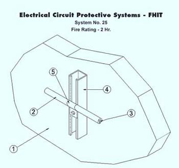
Figure 2. Electrical circuit protective systems
These systems are UL classified under the product category entitled Electrical Circuit Protective Systems, category “FHIT” and are published in volume 2A of the UL Fire Resistance Directories as cross sectional design drawings with detailed descriptions of all the components for installation as a system. These systems are intended for installation as protection for specific electrical wiring systems, with respect to the disruption of electrical circuit integrity upon exterior fire exposure (see figure 2).
Fire ratings apply only to the entire protection system assembly as specified and constructed in each UL classified assembly design. Fire ratings are not assigned to the individual components as stand-alone products and are not interchangeable between systems.
Article 700, Emergency Systems
The proper operation of emergency electrical systems during a fire is critical such that emergency systems can function to assist occupants in the evacuation of a building. NEC Section 700.9(D)(1) identifies the following six methods to provide a level of fire protection for the feeder-circuit wiring for specific occupancies:
1. Installed with buildings that are fully protected by an approved automatic fire suppression system
2. Have a listed electrical circuit protective system with a minimum 1-hour rating
3. Protected by a listed thermal barrier system for electrical system components
4. Protected by a fire-rated assembly listed to achieve a minimum fire rating of 1 hour
5. Encased in a minimum 50 mm (2 in.) of concrete
6. Have a cable listed to maintain circuit integrity for not less than 1 hour when installed in accordance with the listing requirements
The several listed alternatives to fully protecting a building by an approved fire suppression system as referenced in method 1, or encasing the feeder circuit wiring in not less than 50mm (2 inches) of concrete as referenced in method 5, to assure the emergency electrical system will function during a fire will be addressed in detail.
Method 2 was indicated for fire pumps as an option for Section 695.6(B)(3), the use of 1-hour rated listed electrical circuit protective systems is also permitted to protect emergency feeder circuit wiring. Electrical circuit protective systems are typically constructed of fire resistant materials encasing the wiring system and supports, or cables on their own, where the construction of the cable jacket and insulation provide the fire resistance. These systems are UL classified under the product category entitled Electrical Circuit Protective Systems, category “FHIT.” These systems are published in volume 2A of the UL Fire Resistance Directories as cross sectional design drawings with detailed descriptions of all the components for installation as a system.
Method 3 includes listed thermal barrier systems that are typically constructed of heat and fire resistant material wrapped around or encasing the wiring method and support system to prevent the transmission of heat above a specified temperature during the fire test method. Thermal barrier systems are evaluated by the fire exposure test as described in the Standard Test Methods for Fire Tests of Fire-Resistive Barrier Systems for Electrical Components, ASTM E 1725-95.
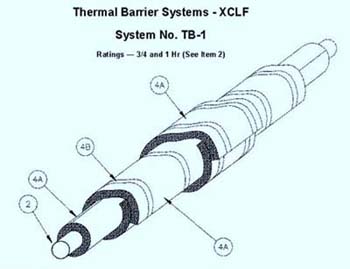
Figure 3. Thermal barrier systems
These systems are UL classified under the product category entitled Thermal Barrier Systems, category “XCLF.” These systems are published in volume 2A of the UL Fire Resistance Directories as cross sectional design drawings with detailed descriptions of all the components for installation as a system (see figure 3).
As with Electrical Circuit Protective Systems (FHIT), Thermal Barrier Systems (XCLF) fire ratings apply only to the entire protection system assembly as specified and constructed in each UL classified assembly design. Fire ratings are not assigned to the individual components as separate products and are not interchangeable between systems.
Method 4. As discussed for fire pumps as an option for Section 695.6(B)(2), the use of a listed 1-hour fire rated assembly is also permitted for this application to protect the emergency feeder circuit wiring. Fire rated assemblies are UL classified under the product category for Fire Resistance Ratings of Building Assemblies–ANSI/UL263, category “BXUV.” This product category covers fire rated assemblies consisting of walls and partitions, floor-ceilings, roof-ceilings, beams and columns. These systems are published in volume 1 of the UL Fire Resistance Directories as cross sectional design drawings with detailed descriptions of all the components and building materials for installation as an assembly to achieve the assigned fire resistance rating.
Method 6. Cables listed to maintain circuit integrity for a minimum of 1-hour during a fire are cables whose cable jacket and insulation provide the fire resistance. The cables comply with the applicable electrical requirements, and also have been investigated for their ability to remain electrically functional during a fire exposure and after the impact, erosion and cooling effect of a water-hose stream test. Fire-resistive cables are investigated for compliance with the Standard for Tests of Fire Resistive Cables, UL 2196 and are intended for installation in accordance with the National Electrical Code.
These cables are UL classified under the product category Fire Resistive Cables, category “FHJR.” They are published in volume 2A of the UL Fire Resistance Directories. This category covers fire-resistive cables, which are insulated electrical cables intended for installation as specified in the individual Electrical Circuit Protective Systems (FHIT) which were previously referenced. Fire Resistive Cables (FHJR) fire ratings apply to the cable as installed in accordance with its UL Classification in the specified Electrical Circuit Protection System (FHIT).
Conductor Ampacity Considerations
When using any type of enclosure or barrier system such as an Electrical Circuit Protective System (FHIT) or Thermal Barrier Systems (XCLF) to provide the fire protection, attention should be directed to Article 310, Conductors for General Wiring, regarding conductor ampacity.
The use of a barrier or enclosure could reduce the allowable conductor ampacity because the barrier acts as an additional thermal jacketing to the conductor and derating of the conductor ampacity may be necessary. The significance of this effect is dependent upon the loads being carried by the conductor and the anticipated duration of the operation of the equipment connected to the conductor.
If the UL classified system does not specify the ampacity reduction due to the electrical circuit protection system or the thermal barrier system for normal ambient conditions, then the effect of the system on the electrical conductor ampacity has not been
UL Listing vs. Classification
The NEC sections refer to listed systems. However, UL refers to classified systems for the fire protection methods referenced in this article. Are they the same? Yes, while the terminology is different. Classification complies with the definition of listed as detailed in Article 100. For purposes of compliance with the Code, the two types of certification are considered equivalent.
Fire Alarms, Article 760 and Circuit Integrity (Ci) Cable
Fire Alarm Circuit Integrity (CI) cable is defined in Section 760.2 as “Cable used in fire alarm systems to ensure continued operation of critical circuits during a specified time under fire conditions.”
Sections 760.31(F) and (G) and 760.71(G) and (I), respectively require non-power limited fire alarm cables (Type NPLF) and power limited fire alarm cables (Type FPL) to be listed as fire alarm circuit integrity (CI) cable and marked with the “CI” suffix. Fine print notes No. 2 to 760.31(F) and 760.71(G) explain that one method of defining circuit integrity (CI) cable is a 2-hour fire resistance rating for the cable in compliance with the Standard for Tests of Fire Resistive Cables, UL 2196.
Circuit integrity (CI) fire alarm cables are fire alarm cables where the cable jacket and insulation is constructed of material that on its own provides fire resistance. They are marked with the fire alarm cable type and “CI (max voltage ___)” to identify that it is suitable for use as circuit integrity cable at the maximum voltage to ground indicated, in accordance with Section 760.31(F) and 760.71 (G) respectively.
In addition to complying with the applicable standards for fire alarm cable, fire alarm circuit integrity (CI) cable complies with the Standard for Tests of Fire Resistive Cables, UL 2196.
Listed fire alarm circuit integrity cable can be located under the following UL product categories, Non-power Limited Fire Alarm Cable (HNHT) and Power Limited Fire Alarm Cable (HNIR). The marking information for the cable is detailed in the UL Guide Information for those two categories in the UL Directory for Electrical Construction Equipment Directory (Green Book) as well as the UL General Information for Electrical Equipment Directory (the White Book).
These categories, as well as all UL product categories, can be located by the four letter category code in parentheses following the product category title (in this case HNHT or HNIR), this four-letter code is the UL product category guide designation, also known as the CCN. The guide information for a product category as well as listings for these product categories can be accessed on UL’s Online Certification Database at www.ul.com/database and entering the code at the UL Category Code/ Guide Information search
Fire Tests
In discussing fire performance requirements contained in Articles 695, 700 and 760, several fire tests methods have been referenced. Except for the test designed for building assemblies, the tests have been developed to measure the ability of electrical cables to remain functional during a fire scenario. These fire tests are intended to subject the electrical cables and their protective enclosures to the environmental conditions that would be anticipated to occur during fully developed fires. The fire tests include the use samples of sufficient size so that the structural performance of the electrical cables together with their enclosures and support systems are also evaluated. These fire tests are conducted in addition to tests traditionally conducted to measure the performance of electrical cables during ambient conditions.
The test samples, approximately 3 meters long, are not limited to just the electrical cable but consist of the complete wiring method system including items such as cables, raceways, cable trays, conduits, protection materials and the means used to support the systems to a horizontal or vertical mounting surface. The protection materials for the cables may consist of building assemblies, such as walls or shafts or could simply be the cable jacketing material as is the case with “CI” cable.
The fire test methods identified in Articles 695, 700 and 760 measure the performance of three types of protection systems: 1) building assemblies, 2) barrier/wrap protection, and 3) cable jacket protection.
Fire Resistive Building Assemblies (BXUV)
UL 263, ASTM E119, NFPA 251
This test method anticipates a complete building assembly such as a wall to be constructed around the safety related electrical circuit. The test method is described in Standard UL 263 (ASTM E119, NFPA 251). For wall assemblies, the sample is typically 10 by 10 feet. At the rating period, the average temperature rise on the unexposed surface of the wall away from the fire is limited to 250°F with no individual temperature rise exceeding 325°F and flaming on the surface of the wall away from the fire is prohibited.
After the fire test the assembly must comply with the hose stream test. The hose stream test consists of water being delivered through a 1-1/8 inch play pipe nozzle at a pressure of 30 pounds per square inch at a flow rate of approximately 200 gallons per minute. The impact pressure applied to the test sample is approximately 58 pounds per square foot.
For acceptable performance, the water stream cannot penetrate through a building assembly.
Electrical Circuit Protective Systems (FHIT)
Thermal Barrier Systems (XCLF)
With Barrier or Wrap Protection
UL Outline of Investigation, SU 1724 / ASTM E1725
This test method is designed for cable systems where the fire protection is provided by a barrier such as a blanket surrounding the electrical raceway or where the electrical raceway is placed within a building assembly such as a wall. The test is described in Standard ASTM E1725, Standard Test Methods for Fire Tests of Fire-Resistive Barrier Systems for Electrical System Components and UL’s Outline of Investigation Subject 1724, “Fire Tests for Electrical Circuit Protective Systems.”
The test method simulates electrical cables by a single bare No. 8 AWG stranded copper conductor. Thermocouples are attached to the copper conductor at 6-inch on-center spacing. The temperatures measured by the thermocouples attached to the conductor determine the fire-resistive performance of the enclosure surrounding the copper conductor. Ratings, such as 1-hour or 2-hour, are based upon the ability of the enclosure or barrier to limit the average temperature rise along the bare copper conductor to 250°F and limit the temperature rise at any point on the conductor to 325°F.
Similar temperature limits are included in the test methods for building assemblies and barriers for cables.
After the fire test, assemblies tested in accordance with UL 1724 must comply with the hose stream test; however, ASTM E1725 does not require hose stream performance. The hose stream test consists of water being delivered through a 1-1/8 inch play pipe nozzle at a pressure of 30 pounds per square inch at a flow rate of approximately 200 gallons per minute. The impact pressure applied to the test sample is approximately 58 pounds per square foot. For acceptable performance, the water stream cannot penetrate through a protective barrier or wrapping resulting in the electrical cable becoming visible.
Electrical Circuit Protective Systems (FHIT)
with Cable Jacket Protection
Fire Resistive Cables (FHJR)
and Circuit Integrity Cable (CI)
UL 2196
This test method is used when the cable jacketing provides the fire-resistive barrier. The test is described in the Standard for Tests for Fire Resistive Cables, UL 2196. When a test is conducted in accordance with Standard UL 2196, the fire-resistive cable is a part of the test sample in lieu of the bare copper conductor. The fire-resistive cable is routed through the test furnace with a minimum of 3 meters of the cable being within the furnace. For this test, the electrical cable is exposed to the same fire as the other protective systems but the acceptance criteria is based upon the ability of the cable to remain functional.
During the fire test, the electrical cable is energized by applying an electrical load equaling the cable’s rated voltage or the cable’s utilization voltage under a low current ranging from 0.25 amps to 0.50 amps. The utilization voltage is defined as the cable’s maximum voltage anticipated during normal usage such as typical line voltages of 120 volts, 240 volts and 480 volts.
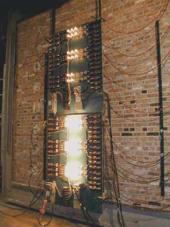
Figure 4
The electrical cable is connected to monitoring lamps that are used to verify circuit integrity. Prior to entering and upon exiting the furnace, the current is continuously monitored to provide leakage current data for the cable within the test furnace. Before and after the fire exposure, the installation resistance of the jacketing material is determined (see figure 4).
For “CI” cables used in fire alarm systems, UL 2196 includes specific mounting methods for the test sample. The cables, without any supplemental barrier or wrapping material, are supported by steel rings spaced 24 inches on center.
Electrical cables tested in accordance with Standard UL 2196 are subjected to the impact and cooling effects of a hose stream test immediately after the fire exposure. Two levels of the hose stream test are available. For circuit integrity “CI” rated cables as defined in the NEC, the water stream is applied through a 1-1/2 inch fog nozzle with the minimum discharge being 75 gallons per minute. The impact pressure applied on the “CI” cables is approximately 0.2 pounds per square foot (see figure 5).
To be considered meeting the acceptance criteria of Standard UL 2196, the cables must remain functional during the fire exposure and after the hose stream tests. Functionality is determined by illumination of the monitoring lamps. Ratings, such as 1-hour or 2-hour, relate to the duration of the fire exposure.
Fire Exposure Intensity
Each of the three test methods include a fire exposure designed to represent a fully developed fire that would be anticipated in industrial, commercial or residential buildings. Temperatures in the furnace chamber for this fire exposure test reach 1000°F at 5 minutes, 1700°F at 60 minutes and 2000°F at 4 hours.
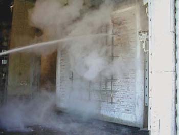
Figure 5
The two test methods designed to measure the performance of barrier/wrap protection or cable jacket protection also include a fire exposure intended to represent a hydrocarbon pool fire such as burning kerosene, oil or alcohol. Temperatures in the furnace when this fire is represented reach 2000°F at 5 minutes and maintain this temperature throughout the duration of the fire exposure which may be up to 4 hours.
Summary
Article 695 for fire pumps, Article 700 for emergency systems and Article 760 for fire alarm systems recognize the need to maintain electrical circuit integrity during a fire such that electrical power is not interrupted to critical circuits under fire conditions.
UL listed or classified products such as Power Limited Fire Alarm Cable (HNIR) or Non-power Limited Fire Alarm Cable (HNHT) with the “CI” marking, Electrical Circuit Protective Systems (FHIT), Thermal Barrier Systems (XCLF), Fire Resistive Building Assemblies (BXUV) and Fire Resistive Cables (FHJR) provide a means to meet those Code requirements.
These product categories, as well as all UL product categories, can be located by the four-letter category code in parentheses following the product category title. The Guide information for each category as well as listings for these product categories can be accessed on UL’s Online Certification Database atwww.ul.com/database and entering the four-letter category code at the UL Category Code/ Guide Information search. This information is also located in the appropriate UL Product Directory.
For more information useful to AHJs, please visit the UL Regulators page atwww.ul.com/database and bookmark it.