Since the beginning of time, we have dealt with hours of darkness every night. Early man had to contend with nocturnal predators, and the best way to survive was to find a safe, comfortable space to rest until sunrise. Modern society brought us artificial lighting, and we now spend both day and night inside buildings.
However, darkness is still a problem when the lights suddenly go out, and we are left to find our way out of an unfamiliar building. For this reason, our modern building codes and standards make provisions to ensure that we are never left in complete darkness for more than a few seconds. One item that tempers this situation these days is that almost everyone has a “flashlight” in their pocket (quit texting for a minute and turn the light on). Nevertheless, the codes account for those occasions when your phone is unavailable, or the battery is dead.
Section 1008 of the International Building Code (IBC) and Chapter 7 of the NFPA 101, Life Safety Code, both require that “Emergency illumination shall be provided for a minimum of 1½ hours in the event of failure of normal lighting” [NFPA 101, paragraph 7.9.2]. These codes also list minimum illumination levels for paths of egress and require that the emergency lights come on within 10 seconds. Finally, as we discuss meeting requirements for emergency lighting, it is important to remember that we need to ensure the lights are on in the egress path, both in the event of a local power outage (a single breaker feeding the lights trips or is inadvertently turned off), or where the entire facility is left in darkness (problems with the electrical utility).
National Electrical Code (NEC) Article 700, Emergency Systems, covers requirements for emergency lighting. In the 2020 NEC, Section 700.16(B) states:
(B) System Reliability. Emergency lighting systems shall be designed and installed so that the failure of any illumination source cannot leave in total darkness any space that requires emergency illumination.
Section 700.17 addresses branch circuits for emergency lighting. In explaining the intent of this paragraph, the NEC Handbook gives the following example:
For example, if a single branch circuit, supplied by an emergency circuit panelboard, supplies the lighting in a stairwell (means of egress), a failure of that branch circuit leaves the stairwell in total darkness. If two branch circuits from separate power sources are run to the stairwell, it is unlikely that both circuits to the stairway would fail simultaneously; therefore, the risk to occupants created by total darkness is minimized.
The actual verbiage for paragraph 700.17 is as follows:
700.17 Branch Circuits for Emergency Lighting. Branch circuits that supply emergency lighting shall be installed to provide service from a source complying with 700.12 when the normal supply for lighting is interrupted. Such installations shall provide either of the following:
(1) An emergency lighting supply, independent of the normal lighting supply, with provisions for automatically transferring the emergency lights upon the event of failure of the normal lighting branch circuit
(2) Two or more branch circuits supplied from separate and complete systems with independent power sources. One of the two power sources and systems shall be part of the emergency system, and the other shall be permitted to be part of the normal power source and system. Each system shall provide sufficient power for emergency lighting purposes.
Unless both systems are used for regular lighting purposes and are both kept lighted, means shall be provided for automatically energizing either system upon failure of the other. Either or both systems shall be permitted to be a part of the general lighting of the protected occupancy if circuits supplying lights for emergency illumination are installed in accordance with other sections of this article.
It is important to note that this paragraph allows the use of either provision (1) or provision (2) to meet the requirement. Also, although the text in the handbook is instructive, it is not binding when enforcing the code. With these thoughts in mind, there are four general methods commonly used for meeting these requirements of the following:
- Discrete battery backed up bugeye units.
- Fitting selected luminaires with integral battery ballasts.
- Standard luminaires fed by a central inverter system.
- Luminaires fed from an on-site generator.
Article 700 also allows the use of uninterruptable power supplies, fuel cell systems, DC microgrid systems, or a separate utility service for emergency power. These, however, are not as common and are beyond the scope of this article. Here we will discuss each of the four methods noted above and address some of the pros and cons for each and pitfalls to avoid with these various approaches. Refer to the chart at the end of the article for comparisons.
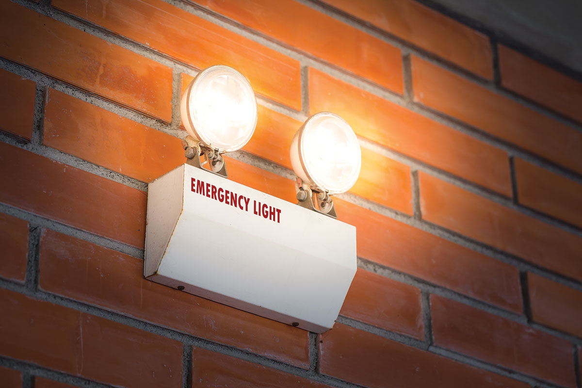
Discrete Battery Pack Units
The simplest solution for providing emergency lighting is to use discrete battery pack fixtures. In their simplest form, these luminaires are traditionally known as bugeye fixtures. These are generally economical to install, recognizable, easy to maintain, and the batteries can be swapped out over time. Because they are inexpensive, it may even be deemed easier to simply replace the units when their batteries run down.
Maintenance for these luminaires is cited in the Life Safety Code, Periodic Testing of Emergency Lighting Equipment [NFPA 101, paragraph 7.9.3]. This testing includes a visual inspection and functional test for 30 seconds every 30 days, an annual 90-minute functional test, and written records of visual inspections and tests kept for review by the authority having jurisdiction (AHJ). This maintenance regimen is the most difficult aspect of using these types of emergency lights. Just like ground-fault circuit interrupter (GFCI) receptacles, they need to be exercised regularly to function properly when needed.
Consequently, just like the manufacturers of GFCI receptacles, the code allows for self-testing/self-diagnostic routines with the units. This function automatically tests the luminaires every 30 days for 30 seconds and an annual full 90-minute test. The status of the testing is shown via LED indicators that change color and/or flash based on the results of the testing. Even when this method is employed, the code requires that these indicators, and the luminaires themselves, be visually inspected at 30-day intervals, and written records of those inspections need to be kept by the owner for inspection by the AHJ [NFPA 101, 7.9.3.1.2].
One other option for testing the battery pack luminaires allowed by the code is to install a computer-based, self-testing/self-diagnostic system to test all the emergency luminaires throughout the facility. This option is by far the most expensive, but it can provide history of tests and failures. Yet, with this system in place, it is still important to remember that the owner needs to occasionally do walk-throughs to ensure that emergency luminaires are not blocked and that the paths of egress are being kept clear.
Some of the best qualities of battery pack luminaires include:
- They are recognizable.
- They are wired to the unswitched portion of the circuit that powers the lights in the area.
- They come on immediately when the power goes out.
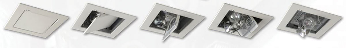
The biggest disadvantage is often these luminaires do not fit in with the aesthetic for the area. There are, however, some options to help with this problem. Luminaire designers have developed flush-mounted emergency battery pack fixtures that retract when not illuminated. This adds a mechanical aspect to their function and, therefore, another possible failure point, but this resolves the aesthetic issue.
The other option is to place a large battery pack with the capacity to power remote heads in a mechanical room and then install recessed remote heads in the ceiling or wall to light the path of egress. These remote heads can be recessed and therefore have a much cleaner look than bugeyes, but there are two potential drawbacks. The first is that the remote heads are low voltage, usually 12V or 24V, and voltage drop becomes a problem much more quickly. The other thing to remember is the circuit powering the large battery pack needs to be the same as the normal luminaires in the area, so when the local lighting breaker trips, the egress path will not be dark.
Luminaires with Integral Battery Packs
Many standard luminaires can be provided with an integral battery backup. This allows the emergency luminaires to look and function just like the other luminaires in the area when normal power is present. But when the power goes out, these battery packs keep a portion of the luminaire on to light the path of egress. Obviously, the battery pack needs to have a connection to the unswitched portion of the local circuit, so it will only come on when the circuit loses power and not every time the light switch is turned off. With the advent of LED lighting, luminaires became much easier to dim and control, and lighting designers frequently use those dimming capabilities. Even in paths of egress, they can set and adjust the lighting the area. Additionally, energy codes require that the luminaires be dimmed in accordance with the presence of sunlight when skylights, clearstory, or other windows are in the area. This control is frequently accomplished using 0-10V dimming.
When the normal circuit loses power, the battery pack ballast/driver senses the loss and forces the emergency portion of the luminaire to come on. Similar to discrete battery pack units, these are designed to maintain the emergency lighting for 90 minutes. They also need to be regularly tested in accordance with the Code as noted, and luminaires with integral battery units can also be provided with the self-testing/self-diagnostic functions. This function is even more essential for these fixtures because they do basically look like all the other luminaires in the area and can get missed during walk-throughs. Often these luminaires are harder to access than the bugeye units. If the facility is large and there are many of these luminaires with integral battery packs, the computer-based, self-testing/self-diagnostic system may become more attractive and more economically feasible.
An Egg and Basket Analogy
We have all heard the saying, “Don’t put all your eggs in one basket.” In the emergency lighting schemes discussed so far, we are basically providing a basket (battery backup) for each egg (emergency light). This is a secure way to design emergency lighting. However, when there are a lot of eggs to carry, a larger basket becomes a more efficient way to carry them.
There are some methods to handle larger quantities of emergency lights with fewer backup power units. Just like the eggs analogy, we need to be extra careful to make sure that our basket is reliable, and we can avoid dropping it and losing all our eggs or ending up in the dark when we really need emergency lighting.
As more eggs get placed into larger baskets, a couple of devices to allow emergency lighting to function properly during facility power outages and when the local lighting circuit breaker trips or is inadvertently turned off.
Automatic Load Control Relay (ALCR)
[NEC 700.26]
Each manufacturer has its own way to do it, but the schematic diagram in Figure 1 shows the basic function of an Automatic Load Control Relay (ALCR). Note that the luminaire always receives power from the emergency power source. This device is designed to turn the emergency light(s) on at full output if there is an overall power outage in the facility or if the local normal power breaker has been tripped or turned off.

To illustrate how this circuit works, Figures 2, 3, and 4 show how it operates in various typical circuit situations.
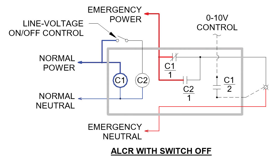

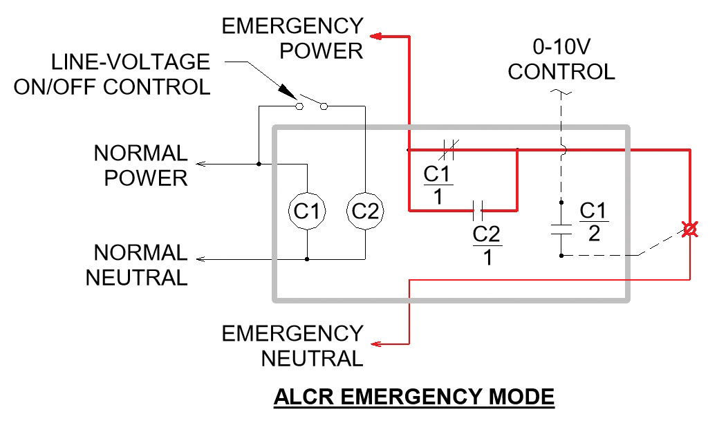
Note that the ALCR is compliant with UL 924 “Standard for Safety of Emergency Lighting and Power Equipment.” This device can be used in 0-10V dimming applications, but this basic version cannot function with line-voltage dimming.
Branch Circuit Emergency Lighting Transfer Switch (BCELTS)
[NEC 700.25]
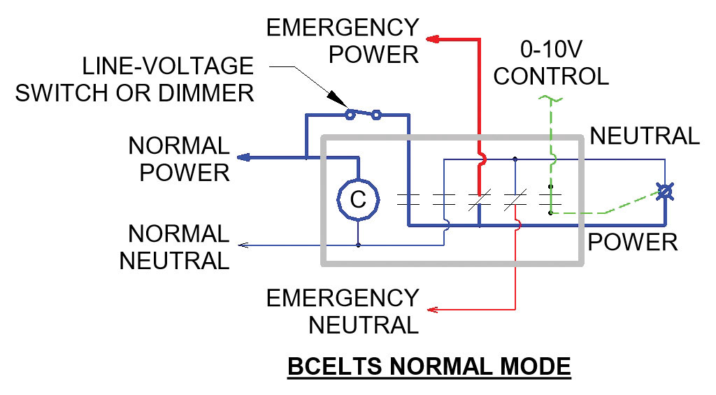
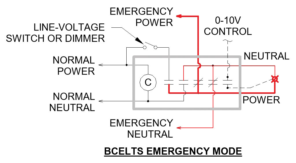
Another device that does a similar job is the Branch Circuit Emergency Lighting Transfer Switch (BCELTS), and figure 5 shows its basic function. When the normal power circuit is available, the luminaire receives power from it and is controlled along with the other luminaires in the area. When normal power is lost, either due to a facility power outage or a local outage, this device swaps the source, and the luminaires is then fed from the emergency power source.
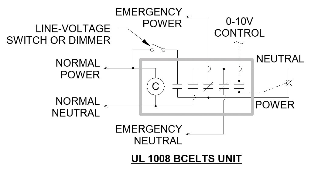
Figures 6 and 7 show how this device operates in the various circuit situations that can be encountered.
Both devices can be used in 0-10V dimming applications. Still, only the BCELTS can be used in 2-wire dimming applications, such as track or decorative lighting that are occasionally used in egress applications. In this case, the line voltage control status is simply passed on through this device when in the normal power condition and does not need to activate a relay coil. The BCELTS is rated to UL 1008 “Transfer Switch Equipment,” which is a more stringent rating than UL 924. Consequently, these devices generally cost more than the ALCRs.
Although not shown in these illustrations, both types of this device have an additional loop for a test switch or fire alarm input. When this loop is broken, the device goes into emergency mode. Finally, it is important to keep in mind that when calculating lighting circuit loads, using the ALCR, the emergency lighting load is always on the emergency circuit. Alternatively, with the BCELTS, that load must be added in with the other lighting on the normal power circuit.
Central Inverter System
A central inverter system has a larger battery that is kept charged under normal power conditions. When normal power is available, it is simply passed on to the emergency lights. But when normal power is lost, the inverter converts the battery’s DC power to line voltage AC power to feed standard luminaires that serve as emergency lighting. When this occurs, the emergency lighting will need to turn on at full output and override any switch that has the lighting dimmed or turned off. Therefore, either an ALCR or a BCELTS must be installed in the circuit to force the luminaire on at full output.
NEC 700.12(F)(2)(3) discusses the installation of battery equipment used for emergency lighting backup. Part of this section in the 2017 Code calls for the branch circuit that feeds the unit equipment to be on the same circuit as the one serving the normal lighting in the area. There is one exception to this requirement:
Exception: In a separate and uninterrupted area supplied by a minimum of three normal lighting circuits that are not part of a multiwire branch circuit, a separate branch circuit for unit equipment shall be permitted if it originates from the same panelboard as that of the normal lighting circuits and is provided with a lock-on feature.
In the 2020 NEC, this section was moved to 700.12(I)(2)(3) and changed to read:
(3) The branch circuit feeding the unit equipment shall be one of the following:
-
- The same branch circuit as that serving the normal lighting in the area and connected ahead of any local switches
- Where the normal lighting circuit is served by one or more branch circuits, a separate branch circuit, provided with a lock-on feature, that originates from the same panelboard as the normal lighting circuits. The branch circuit disconnecting means for this branch circuit shall be provided with a lock-on feature.
This change may seem like a step toward less emergency lighting circuit reliability, but it is acceptable because ALCRs and/or BCELTSs are used for the emergency lighting circuits.
Figure 8 shows where the inverter is handling the emergency lighting in three separate egress corridors with three separate circuits. Only the top corridor has the same circuit for the inverter and the normal lighting.
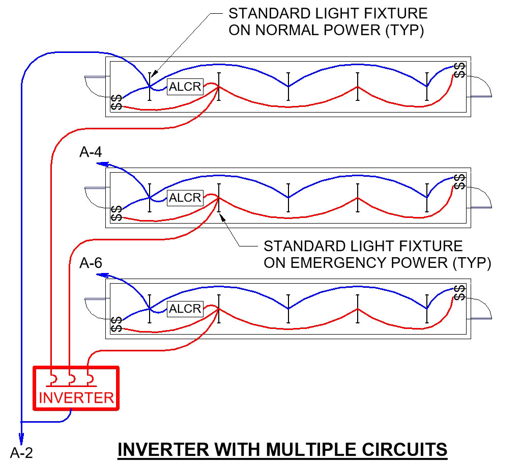
The following three instances demonstrate the inverter’s ability to provide proper emergency illumination in various branch circuit scenarios (see Figure 8).
- If there is a facility-wide power outage, the inverter is activated, and it supplies emergency power to each of the three corridors. The ALCRs would force the emergency lights in those corridors to come on at full power.
- If just circuit A-2 loses power, the inverter is activated and supplies power to the emergency fixtures in each corridor. Only in the top corridor would the ALCR force those emergency lights to full output.
- Now, if power is only lost on circuit A-6, the ALCR in the bottom corridor would force those emergency lights to full output to allow for safe egress. The inverter would not go to emergency battery mode but would simply pass the normal power from circuit A-2 — which has not been affected by an outage — onto the emergency lights in the bottom corridor.
Because the ALCRs react to a local power outage, the inverter can serve in as many separate circuits as needed.
Finally, some of the smaller inverters, up to about 250W, have the ALCR function built-in. The advantage here is if a single circuit is being backed up, the switched normal power and 0-10V dimming can simply be routed through the inverter, and a stand-alone ALCR would not be required. Some of these units can also dim the emergency luminaire to allow for more light fixtures and emergency illumination.
On-site Generator
Unless the building is a high rise or exceptionally large, a generator would not normally be installed just to power the emergency lighting. However, building owners are becoming increasingly sensitive to power interruptions and need backup power. Data centers, banks, manufacturing facilities, law enforcement, fire/emergency facilities, detention centers, healthcare buildings, labs, and transportation centers are candidates for on-site generators. For some of these facilities, the codes require backup power, and when it’s available, it seems obvious to use it for emergency lighting. There are, however, a number of factors that need to be weighed first.
Using a generator for emergency lighting means that at least that portion of the system must be dealt with as an emergency system [Article 700]. Therefore, the requirements are significantly more stringent than for those with either a legally required standby system [701] or an optional standby system [Article 702]. A few of these requirements include:
- A permanent switching means to connect a portable/temporary source whenever the generator must be disabled for maintenance or repair [700.3(F)].
- The emergency portion of the generator system needs its own transfer switch [NEC5(D)].
- A surge protection device is required for each emergency system panelboard [NEC8].
- Wiring for the emergency system must be kept entirely independent of all other wiring and equipment [700.10(B)].
- Emergency system generators, transfer switches, and circuits need to be located where adverse conditions won’t be present [700.10(C)] and [700.12(B)].
- Depending on occupancy, there are additional requirements for fire protection [NEC10(D)] and [700.12(B)].
- Since a generator must start, get up to speed, and then transfer power, there is an inevitable lag time for the lights to come back on. For emergency systems, the generator needs to supply power within 10 seconds of a power outage [700.12]. A legally required standby system has 60 seconds to supply power [701.12], and an optional standby system does not have a time limit. Modern generators can come online within 5 or 6 seconds, but is the facility such that occupants can deal with this delay? In some situations, that delay might be enough to cause panic.
- The generator set must comply with more stringent requirements than it would when backing up less vital loads [700.12(D)]
Two Generator System Use Cases
Health care facilities typically use emergency lighting that is fed by a generator system. Requirements for these facilities are covered in Article 517, where the essential electrical system consists of a life safety branch, a critical branch, and an equipment branch.
- The loads that can be fed by the life safety branch are very restricted, and they include illumination of the means of egress [517.33(A)]. Loads on the critical branch can include task illumination [517.34(A)]. Unless the facility is very small, with the essential electrical system being 150kVA or less, each of the three branches will have separate transfer switches [517.31(B)].
- As discussed for emergency lighting under Article 700, the egress lighting on the life safety branch needs to be forced on at full capacity via an ALCR or BCELTS.
- However, task lighting on the critical branch would not require an ALCR or BCELTS since those luminaires do not affect building egress and may need to stay dimmed — or off — during a power outage. With that in mind, it is also important that the lighting controls in those areas are not solely on normal power but will continue to control the task lighting in a power outage situation properly.
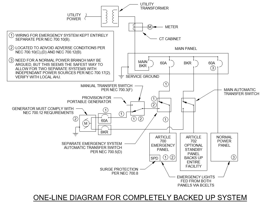
Another issue comes up when an entire facility is backed up with generator power. To meet NEC 700.17 (2), “Two or more branch circuits supplied from separate and complete systems with independent power sources,” it becomes necessary to include a small branch of power that is not backed up by the generator. Otherwise, a failure with the generator system or its distribution could leave the paths of egress completely dark even when the normal power is available from the utility (see One-Line Diagram for Completely Backed Up System in Figure 9).
General Generator Notes
Do not forget that to meet Section 700.17, local power outages need to be addressed as well as overall facility outages. As with a central inverter system, standard luminaires become emergency lights, so either an ALCR or a BCELTS must be installed in the circuit to force the luminaire to full output when overall or local normal power is lost.
If the generator is used for emergency lighting, the system needs to be thought through carefully and all the additional provisions must comply with Article 700. In addition, some jurisdictions will also require that the generator system complies with requirements of NFPA 110, Standard for Emergency and Standby Power Systems.
Finally, if the normal power goes out, and your generator system fails to start, transfer power, or another failure, the darkness will be complete. This is the ultimate case for having all your eggs in one basket that just hit the floor with disastrous consequences!
Final Thoughts
Always keep in mind that the design of the emergency lighting system is just the beginning and that a consistent maintenance routine needs to be followed to ensure the system will work when needed. Emergency lighting system designers and installers can help by specifying and supplying systems that can self-test and self-diagnose problems. Ultimately, when the applicable requirements of NEC 700.12 and NEC 700.17 are carefully followed, we can rest assured that no one will ever be left in complete darkness for more than a few seconds and will always have a lighted way to safely exit the building.
References
- NFPA 70 – National Electrical Code (2020 Edition)
- NFPA 70 – National Electrical Code Handbook (2020 Edition), Mark W. Earley, P.E.
- NFPA 101 – Life Safety Code (2018 Edition)
- IBC – International Building Code (2018 Edition)
| Pros | Cons | Considerations | ||
| Discrete Battery Pack | Surface Bugeye | · Instant on.
· Naturally wired to the local lighting circuit. · Stand out asking to be observed/tested. · Inexpensive. · One egg per basket. |
· Aesthetics issues.
· Many batteries to maintain. |
· Be sure to specify self-testing/self-diagnostic function.
· Visual inspections with records required. |
| Recessed Bugeye | · Instant on.
· Naturally wired to the local lighting circuit. · Aesthetically fits in. · One egg per basket. |
· Easier to miss in testing/maintenance.
· Many batteries to maintain. · More expensive. · Additional mechanical failure point. |
· Be sure to specify self-testing/self-diagnostic function.
· Visual inspections with records required. |
|
| Remote Heads | · Instant on.
· Aesthetically fits in better than bugeye. · Fewer batteries to maintain. |
· Care must be taken to circuit to the local lighting circuit.
· Batteries are larger and more expensive to replace. · Voltage drop (distance) considerations · More eggs per basket. |
· Be sure to specify self-testing/self-diagnostic function.
· Visual inspections with records required. |
|
| Luminaires with Integral Battery Pack | · Instant on.
· Fixtures match other fixtures in area. · Simple installation and wiring for electrician. · One egg per basket. |
· Can be hard to access and easier to miss for manual testing/ maintenance.
· Many batteries to maintain. |
· Emergency portion of fixture is less than full fixture output.
· Be sure to specify self-testing/self-diagnostic function. · Visual inspections with records required. |
|
| Central Inverter | · Instant on.
· Fixtures are equal to other fixtures in area. · Less equipment to maintain. |
· ALCRs or BCELTs are required (more complex wiring for electrician).
· Batteries are larger and more expensive to replace. · Many eggs per basket. |
· Be sure to specify self-testing/self-diagnostic function.
· Visual inspections with records still required. |
|
| Generator Backup | · Fixtures are equal to other fixtures in area.
· Often generator is already being supplied for the building. · Less equipment to maintain. |
· Separate Emergency System ATS is required.
· Up to 10-second delay to come on. · ALCRs or BCELTs are required (more complex wiring for electrician). · Much more involved equipment maintenance. · All the eggs are in one basket. |
· Must comply with requirements for NEC Article 700 system:
o NEC 700.3(F). o NEC 700.5(D). o NEC 700.8. o NEC 700.10(B). o NEC 700.10(C). o NEC 700.10(D). o NEC 700.12(B). o NEC 700.12(D). · Visual inspections with records still required. |
|