So sayeth the inspector when faced with inspecting his or her first rooftop residential or commercial PV installation. Yes, PV systems have some unusual wiring methods allowed by the Code. However, since all of the usual wiring methods found in chapter 3 of the Code also apply, the inspector must sort through what is allowed and what has been installed by the typical do-it-yourselfer or other uninformed installer of electrical equipment. Business will be as usual, with only a few small twists to learn.
CONDUCTORS FOR PV MODULES
Before we address these “new” or unusual wiring methods for PV modules, let’s cover the old standbys found in chapters 3 and 4 of the Code. Any wiring system that is suitable for the environment is acceptable for a code-compliant installation. The environment is tough with wide ranging temperatures and moisture. (See sidebar A for the environment in which PV modules operate). This usually dictates a wiring method rated for outdoor, hot (70°–80°C) and wet conditions. Some wiring methods are not suitable for outdoor wet environments, some are not suited for hot environments, and some are not sunlight resistant. In addition to wiring methods using conductors in a raceway, tray cable (type TC) might be considered and it is found attached to some PV modules with a connector.

Photo 1. Modules on tracker
Some PV modules are mounted on devices called trackers that move slowly throughout the day to follow the sun, thereby increasing the PV module output (see photo 1). Section 690.31(C) permits (does not require) the use of appropriate portable power cables found in Article 400 as long as they are suitable for the environment. However, the “extreme” rotational rate of these devices (900 revolutions per decade J) does not usually indicate that these flexible portable power cables are required on trackers. Normal stranded cables in flexible conduits have passed the test of time. Of course, portable power cables may not be used on fixed, non-moving/vibrating electrical systems or on fixed PV module installations.
“New” PV Module Wiring Methods

Photo 2. Early PV module terminal
In addition to all of the normal wiring methods allowed in chapters 3 and 4 of the Code, 690.31(B) permits (does not require) the use of exposed single-conductor cables for interconnecting PV modules. Cable types USE, USE-2, SE, and UF (where marked sunlight resistant) are permitted. This allowance was added to the Code in the 1984 edition because many PV modules had separate positive and negative output terminals that were as much as six feet apart and the PV industry deemed that it was not practical or cost effective to run raceways or multiple-conductor cables to both locations for a single contact (see photo 2). Since this electrical wiring was usually roof-mounted in relative inaccessible locations, the code-making panel deemed that the safety issues were minimal. Somehow, it was not mentioned that some of those early PV modules had no junction boxes and some even had exposed terminals that had to be covered. Some ceiling heating panels have similar connection arrangements.

Photo 3. Conduit ready PV module
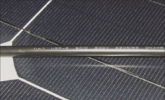
Since 1984, when Article 690 was first added to the Code, PV modules have improved significantly and there are two main types of electrical connections for the modules. Many have plastic terminal/junction boxes firmly attached to the back of the module. These junction boxes have conduit knockouts that will normally accept 1/2″ trade size conduit or cord grips for single conductor cables (see photo 3). Other modules use appropriate (usually USE-2) pigtail conductors permanently attached to the module with connectors on the ends (see photo 4). The two pigtail conductors (one for the positive output and one for the negative output) allow easy series connection of the PV modules to form strings of modules for the higher voltage systems (24, 48 and 200–600 volts).

When modules with junction boxes are used, the single conductor cables should have adequate strain relief. Normally this dictates the use of a cord grip in the knockout and that device should be listed for use outdoors. A few modules have, in addition to the knockouts, a small hole (about 1/4″) that will accept the conductor directly. A silicon gasket in the side of the junction box provides a raintight seal where the conductor penetrates. Inside the junction box is a plastic post and the conductor must be wire-tied/wire-wrapped to this post for strain relief.

These single-conductor exposed cables should only be used to make connections between modules and from the modules to a nearby junction box where the wiring method transitions to a more conventional wiring method (see photo 5). The conductors should be securely fastened to the module frames and support structure to meet good workmanship standards. At the very least, outdoor rated plastic wire ties/wire wraps should be used, but for more durability, many installers use insulated metal clamps.
Conductor Selection

It should be noted that USE-2 cable with no other marking does not have the necessary flame-retardants for use inside buildings. Dual marked USE-2/RHW-2 cables and SE cables do have the necessary flame-retardants, and a single cable type can be used from the PV modules to the final utilization equipment. Of course, the sections inside the building would have to be installed in an approved raceway.
The environmental conditions in the module junction box and along the backs of the modules dictate that wet-rated 90°C conductors be used when in conduit. The 90°C requirement comes from the high operating temperatures of the modules, and the wet requirement comes from the fact that all outdoor locations are considered wet locations. In conduit, these cables would be THWN-2, XHHW-2, RHW-2 and similar cables.
Current and Voltage Ratings
Conductors must be able to withstand the voltages and currents impressed upon them by the widely varying outputs of the PV system. For several reasons, the electrical design of PV systems (as required in Article 690) is based on worst-case conditions. Only continuous (three hours or more) power production is used and that power production is estimated at the worst-case level. There are no non-continuous energy sources.
Early PV module manufacturers, inverter manufacturers, Underwriters Laboratories, and individuals involved with codes and standards recognized that these variations in temperature and irradiance from Standard Test Conditions affected the module output and had to be addressed. (See sidebar B for information on how PV modules respond to the environment).
Excessive, unexpected voltages could cause arcing in switchgear and overcurrent devices, deterioration and breakdown of the insulation on conductors, and damage to electronic devices like inverters, charge controllers, and the PV modules themselves. Higher-than-rated currents

Figure 1. Solar power vs. time
could cause nuisance tripping of overcurrent devices, overheating of conductors, and the subsequent deterioration of the conductors as well as failed switchgear, electronic devices, and power relay contacts.
PV Adjustment Factors
For the reasons stated above, the early PV pioneers developed mathematical tools to deal with the uncertain nature of the dc voltages and currents. The following instructions are found in the instruction manual supplied with every listed PV module—everyone reads the manuals don’t they?
The rated short-circuit current (at STC as marked on the back of the module) is to be multiplied by 125 percent to account for those bright, sunny days where the irradiance is above 1000

Figure 2. PV-IV operating curve
W/m2. This is done before any instructions/requirements in the NEC are implemented. This current then becomes the continuous current used for ampacity and rating calculations in the Code.
The rated open-circuit voltage (at STC as marked on the back of the module) is to be multiplied by 125 percent to account for those bright, sunny and cold, windy days. This is also done before any instructions/requirements in the NEC are addressed and the resulting voltage is the system voltage.
These new values of voltage and current are then used to determine the voltage ratings and the ampacity of the conductors. Future Perspectives on PV will address the application of these factors. In a hurry? See the last paragraph for more information.
CONDUCTORS FOR BATTERIES


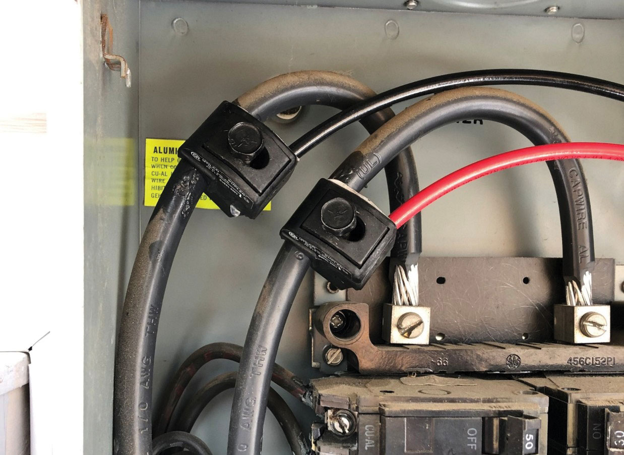
Unfortunately, many PV installers have little experience in pulling these larger cables through conduit so many of them look for more flexible cables to ease the installation. The local auto supply shop has “battery” cables (unlisted) that appear to cover some of the size ranges, and local welding shops have welding cables (listed and unlisted) that appear to be suitable. However, neither battery cables nor welding cables have been tested and evaluated for use in fixed electrical power systems under the NEC. Article 630 mentions welding cables in conjunction with the secondary circuits of electric welding machines and installation in cable trays. Code-making panel 13 rejected a 2005 NEC proposal to use welding cable for battery connections as “Not listed for the application.” At least one sample of an unlisted welding cable used in conduit at nominal current levels for only 10 years was found to have the insulation cracked all the way to the conductor (see photo 8).
NEC chapter 3 conductors are available in fine-stranded versions in types RHW and THW; however, a special order is often required. Of course, the normal 7–13 strand THHN, RHW, THWN and similar conductors are suitable and can be used without significant difficulty (for the experienced) when the Code requirements for wire bending space and conduit fill are met in the equipment.
Future Perspectives on PV will address the ampacity calculations for the conductors used in PV systems.
For Additional Information
If this article has raised questions, do not hesitate to contact the author by phone or e-mail. E-mail: jwiles@nmsu.edu Phone: 505-646-6105
A PV Systems Inspector/Installer Checklist will be sent via e-mail to those requesting it. A copy of the 100-page Photovoltaic Power Systems and the National Electrical Code: Suggested Practices, published by Sandia National Laboratories and written by the author, will be sent at no charge to those requesting a copy with their address by e-mail. The Southwest Technology Development web site (http://www.nmsu.edu/~tdi) maintains all copies of the “Code Corner Columns” written by the author and published in Home Power Magazine over the last 10 years.
The author makes 6–8 hour presentations on “PV Systems and the NEC” to groups of 40 or more inspectors, electricians, electrical contractors, and PV professionals for a very nominal cost on an as-requested basis.
Sidebar A
PV Modules Operating in Extreme Environments
The environment in which PV modules operate affect the electrical safety of PV installations and drive the installation requirements found in the National Electrical Code.
ENVIRONMENTAL CONDITIONS
Sunlight
The intensity of sunlight is called irradiance, and for PV systems the units are watts per square meter (W/m2). A square meter is about 11 square feet. A typical, clear sky, solar noon value of irradiance falling on the surface of the earth at sea level is 1000 W/m2. This value of irradiance is one of the Standard Test Conditions (STC) factors used to rate PV module and PV array output.
On clear, cloudless days, the magnitude of irradiance will peak at solar noon. A plot of the irradiance vs. time of day is presented in figure 1 and makes an arc-like curve. PV system designers need to know the amount of solar energy available each day (known as irradiation or insolation), and working with the irradiance vs. time curve is difficult since it requires mathematical integration of the data. To simplify the calculations used in PV system design, tables are provided that do the math and present the available solar energy as the period of time that the solar irradiance is at the 1000 W/m2 level. This is seen in figure 1 as the rectangular area with the top at 1000 W/m2. The width of the rectangle in hours is known as the peak sun hours. This peak level of irradiance will vary depending on a number of factors including orientation of the surface, altitude, and the local microclimate. The PV designer has access to this information for many regions and locations throughout the country. However, solar irradiance greater that 1000 W/m2 may be expected in many locations where PV systems are installed. At higher elevations, there is less air between the surface and the sun (atmospheric density is lower) and the range of irradiance values is higher than at sea level.
In many areas, the time period that the irradiance exceeds 1000 W/m2 can be three hours or more. This has an impact on the electrical design of the PV system. The peak may be any value above 1000 W/m2, and values in the range of 1100–1200 W/m2 are common. Short-term (10–15 minutes) peaks of over 1400 W/m2 have been measured when cumulus clouds have formed a refractive lens around the sun and concentrated the sunlight on the surface.
Temperatures
PV modules are rated (power, voltage, current) at a Standard Test Condition (STC) temperature of 25°C (77°F). Surfaces (including PV modules) mounted in exposed outdoor locations are subject to widely varying temperatures that are a result of the ambient temperatures, solar exposure and cooling by radiation and convection. A typical PV module mounted outdoors in a well-ventilated area and exposed to 1000 W/m2 of solar irradiance with no wind blowing can be expected to operate at 30–35°C above the ambient temperature. If the ambient temperature were 40°C (104°F), the typical PV module would operate in the 70–75°C range on hot sunny days during the peak solar period.
On the other hand, a PV module operating in cold, windy weather may have the cold winds remove heat so rapidly from the module that the sun never increases the module temperature more than a very few degrees above ambient temperatures. With winter ambient temperatures in some locations in the U.S. as low as –40°C (-40°F), modules can operate at these temperatures. Furthermore, surfaces facing the clear, nighttime and early-morning sky may be subject to radiation cooling and the surface may be a few degrees cooler than the ambient temperature.
Sidebar B
PV Module Characteristics
The rating of PV modules is done under a set of Standard Test Conditions. However, crystalline silicon PV modules respond to the widely varying environmental conditions addressed in sidebar A. From a performance perspective (needed to calculate the output of the PV module/system) the power output is directly proportional to the irradiance and has an inverse relationship with the module operating temperature. If irradiance increases by 10%, the power available from the module will also increase by 10%. As the module temperature increases above the 25°C (77°F) level, the module power output will drop about 0.5% per degree C increase in temperature. Conversely, if the module temperature decreases, the power output will increase about 0.5% per degree C. When a PV module operates at 75°C (experienced on hot sunny days with no wind), the output may be only 75% of the STC rated output due to the increased operating temperature. Module power output is the product of the output current and the output voltage. Typically at the peak-power point on the module operating curve (IV curve–see figure 2), the peak-power voltage will change about -0.5% per degree C and the module peak-power current will change very little with respect to temperature; voltage being the primary temperature-dependent factor in the power equation in this region of operation.
For safety purposes and to meet code requirements, the manner in which the open-circuit voltage and the short-circuit currents vary must be determined. For silicon PV modules, the open-circuit voltage is an inverse function of temperature. As temperature decreases, open-circuit voltage increases at about 0.38–0.4%/°C. At a module operating temperature of –40°C (-40°F), the open-circuit voltage may be 25% higher than the STC value. Open-circuit voltage is only slightly influenced by the irradiance. Obviously in total darkness, the voltage output is zero. However, even in dim light (dusk, dawn, heavy clouds) the open-circuit voltage is very nearly the STC rated value. Direct sunlight does not have to be shining on the module for the voltage to be on the output terminals; very little current may be available, but nearly full voltage can be expected in dim light. Thin film modules (as opposed to the more common crystalline silicon modules) may have different characteristics.
The short-circuit current is a direct function of irradiance. Increase or decrease the irradiance 20% and the short-circuit current changes by the same percentage and in the same direction. Short-circuit current also increases a slight amount as the module temperature increases, but this effect is generally ignored in PV design.
Overall Environmental Impacts on Module Performance
With the irradiance and temperature variations addressed in sidebar A, PV modules may be expected to have open-circuit voltages from about 15% below the STC value in hot, still weather to about 25% above the STC value in cold, windy weather. The short-circuit current may be 120% or more of the STC value on sunny, hot days and that output may exist for three hours or more.


Find Us on Socials