Nearly everyone agrees that the National Electrical Code gets better with every edition. However, new technologies like photovoltaic (PV) power systems and fuel cells are still evolving with new equipment, new wiring procedures, and new installation requirements being developed every week. With new inspectors and new installers coming into the field every day, questions are bound to arise. The question addressed below is very common and is frequently posed by both oldtimers and newcomers. The answer is not directly found in the Code but must be evaluated on a case-by-case basis by examining the system.
When are overcurrent devices (fuses or circuit breakers) needed in the direct current circuits between the PV modules and the utility-interactive inverter?
Before answering this question directly, we first should address the issue that properly rated fuses and properly rated circuit breakers are equivalent in this application and are collectively known as overcurrent protective devices (OCPD). This is true even though the required label on the back of certified/listed PV modules says “Fuse.” In general, PV arrays operating at dc voltages above about 150 volts (cold-weather, open-circuit voltage) may use fuses, and those operating below this voltage may be using either fuses or circuit breakers. These applications are due to the ratings, availability, and cost of the different devices.
In most electrical systems, theNECrequires that every ungrounded circuit conductor be protected from overcurrents that might damage that conductor. Overcurrent protective devices, either fuses or circuit breakers, provide that function. However, some of the smaller utility-interactive PV systems may not need OCPD in the dc circuits that are connected to the PV modules.
PV modules are current-limited devices, and their worst-case, continuous outputs for Code calculations are 1.25 times the rated short-circuit current. An exception to Section 690.9(A) allows conductors to be used with no OCPD where there are no sources of external currents that might damage that conductor.
The module series fuse requirement
External sources of current vary from system to system. These external currents can originate from modules or series-connected strings of modules that are connected in parallel to the module of interest, from batteries in the system backfeeding through charge controllers, or from utility currents backfeeding through utility-interactive inverters. The material below will deal only with the utility-interactive PV system with no batteries in the system.
Where required, only one OCPD will protect all modules connected in a single series-connected string of modules [690.9(E)]. A properly rated and located OCPD can protect the modules and properly rated conductors from external overcurrents.
Utility-interactive inverters and backfeed currents from the utility
Many of the smaller utility-interactive inverters (below about 10 kW) are designed so that they cannot backfeed currents from the utility into array faults. However, there are currently no normal operation tests in UL 1741 to validate the lack of backfeeding from the utility, so a manufacturer’s certification should be obtained that the inverter cannot backfeed from the utility into an array fault. Yes, there are abnormal operation tests for backfeed, but theses tests do not rule out backfeed during normal operation of the inverter. Larger inverters and inverters designed for transformerless or bipolar operation may require additional certification that they cannot backfeed.
The most common case—systems with inverters that cannot backfeed from the utility
A basic question is, How many PV modules or strings of modules can be connected in parallel and still meet the National Electrical Code and Underwriters Laboratories requirements (marked on the back of each module) before an OCPD is needed on each module or string of modules?
UL marks the modules based on reverse-current tests as described above. The NEC requires that the manufacturer’s instructions and labels be followed [110.3(B)]. This is a maximum value for the OCPD. Lesser values can be used as long as they meet the NEC requirement of 1.56 times the module short-circuit current (1.56 Isc) to protect the conductor associated with the module or string of modules [690.8(A)&(B)].
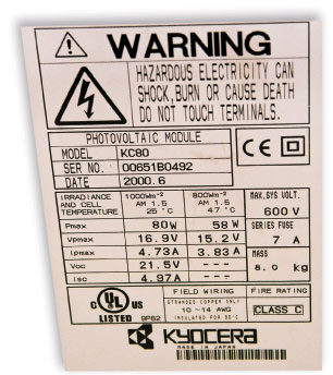
In a few cases, module manufacturers have not met (or understood) the Code requirements, and the value of the module protective overcurrent device marked on the back of the module is less than 1.56 Isc (see photo 1). This poses a Code conflict 110.3(B) vs. 690.8,9 and is an issue for UL to rectify.
One string of modules
Now let’s look at a PV system with several strings of modules connected in parallel. Keep in mind that we are not determining the rating of any required OCPD, we are merely making some calculations that determine whether or not an OCPD is needed on each string of modules.
Two strings of modules in parallel
Consider two modules or two strings of modules connected in parallel, then connected to the inverter input. Each string of modules can generate a maximum of 1.25 Isc. If a fault occurs in one string, the second, unfaulted string can try to force 1.25 Isc amps into the faulted string. However, we know that the modules in the faulted string can withstand currents up to at least 1.56 Isc or higher (if their marked series fuse rating is higher), and the conductors have an ampacity of at least 1.56 Isc or greater. Therefore, with only two strings of modules, no currents exist in the PV array that can damage the modules or the wiring and no OCPD are required.
Three strings in parallel
Now let us consider a system with three strings of modules connected in parallel. A fault in one string could see currents from the two other unfaulted strings. Each of these unfaulted strings could deliver up to 1.25 Isc under worst-case conditions for a total of 2 x 1.25 Isc =2.5 Isc. Suppose that the module manufacturer had a value of the maximum series fuse marked on the back of the module of exactly 1.56 Isc and the wiring was sized at exactly 1.56 Isc. The currents from the two unfaulted strings at 2.5 Isc would be greater than the series fuse rating of the module and ampacity of the conductors at only 1.56 Isc and they could be damaged. Fuses in all three strings at a minimum value of 1.56 Isc would be required.
However, the module manufacturer does not usually have a marked maximum fuse value of exactly 1.56 Isc. Typically, the module will pass the UL reverse-current tests at a higher current such as 15 amps. As an example, let’s take a module that has a short-circuit current (Isc) of 5 amps and a marked value of the maximum series fuse of 15 amps. The interconnecting conductors between the modules must also have an ampacity of 15 amps, after the appropriate deratings for conditions of use have been applied if the conductors are to be protected. In a system with three series strings of this module, the two unfaulted strings could deliver 2 x 1.25 x 5 = 12.5 amps. Since this current is less than the 15-amp ampacity of the conductors and is also less than the 15-amp maximum series fuse requirement marked on the back of the module, no fuses are required because no damage can be done by overcurrents.
In another example, the module wiring is still 15 amps, as is the fuse rating marked on the back of the module. However, this module has a short-circuit current of 8 amps. The two unfaulted strings could send up to 2 x 8 x 1.25 = 20 amps. This 20 amps exceeds both the conductor ampacity and the ability of the module to withstand reverse currents, so fuses are required in each string of modules. The OCPD must be at least 1.56 Isc (1.56 x 8 = 12.48 amps) and not more than 15 amps. A 15-amp OCPD would normally be used.
Modules with low Isc and high series fuse ratings
Some modules have a low, short-circuit current and a high, maximum series fuse rating. For example, a module with a 1.5-amp Isc and a 20-amp maximum series fuse can have up to 11 strings of modules in parallel without any OCPD. The reader is encouraged to verify this—the author may be wrong.
As can be seen from these three examples, when more than two strings of modules are connected in parallel, a calculation should be done to see if the OCPD is required in each string. When three strings of modules are connected in parallel without fuses, the conductor ampacity may have to be greater than the normal 1.56 Isc.
Larger systems and possible inverter backfeed
Summary
Most utility-interactive PV systems with only one or two strings of PV modules will not require OCPD in the dc wiring between the PV array and the inverter. Systems with three strings or more will require a simple calculation to determine the OCPD requirements. Most current inverters rated at less than 10 kW are not able to backfeed currents from the utility into the dc wiring, but larger inverters and inverters that may be transformerless or designed for bipolar operation should be certified for no backfeeding. For a slightly more technical approach to these requirements and calculations, see Appendix J in the author’s PV Power Systems and the 2005 NEC: Suggested Practices manual (below).
For additional information
If this article has raised questions, do not hesitate to contact the author by phone or e-mail. E-mail: jwiles@nmsu.edu Phone: 575-646-6105
A color copy of the latest version (1.7a) of the 150-page,Photovoltaic Power Systems and the 2005 National Electrical Code: Suggested Practices, published by Sandia National Laboratories and written by the author, may be downloaded from this web site: http://www.nmsu.edu/~tdi/Photovoltaics/Codes-Stds/PVnecSugPract.html
The Southwest Technology Development Institute web site maintains a PV Systems Inspector/Installer Checklist and all copies of the previous “Perspectives on PV” articles for easy downloading. Copies of “Code Corner” written by the author and published in Home Power Magazine over the last 10 years are also available on this web site: http://www.nmsu.edu/~tdi/Photovoltaics/Codes-Stds/Codes-Stds.html
The author makes 6–8 hour presentations on “PV Systems and the NEC” to groups of 40 or more inspectors, electricians, electrical contractors, and PV professionals for a very nominal cost on an as-requested basis. A schedule of future presentations can be found on the IEE/SWTDI web site.