Plan Reviewers and Inspectors. What Do You Need?
Photovoltaic (PV) power systems are becoming more numerous, larger and more complex. Inspectors and plan reviewers have limited time to deal with these new systems and still carry on the routine electrical system inspections that have been done for 100 years or more. I intend for this “Perspectives on PV” articles to provide you with information on the Code requirements for these systems and also give you information on how to make the plan reviews and inspections easier and faster.
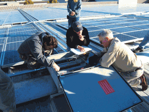
Inspecting PV Systems
What do you need to know about concerning PV systems? Give me a call or drop me an e-mail and let me know what you would like to see in these articles. There will be a time delay since I am writing this November-December 2011 IAEI News article in August. In a hurry for an answer? Try the e-mail and I’ll try to get a fast response.
On the Front Lines
Plan reviewers and inspectors bear a heavy responsibility for the safety of the public when it comes to electrical systems, including PV systems. While most residential and small commercial electrical systems have not changed much over the past few decades or so, PV systems now have transformerless inverters for ungrounded PV arrays, microinverters, AC PV modules, dc to dc converters in the PV array and dc PV arc fault circuit protection. Couple those new “toys” with the dc current-limited outputs from the PV modules and we have a very dynamic, constantly evolving situation.
I know that many jurisdictions do not have a plan review section or person and that many inspectors only have 15–30 minutes allocated to perform a residential inspection. We all know that there are both qualified and unqualified people doing electrical installations, including PV systems. And with the significant amounts of money flowing into green electrical systems, there are many people jumping on the bandwagon that should not even be near the parade.
In this Perspectives on PV, I will share with you a PV installer checklist that covers the more import Code requirements for PV systems. The checklist will show 2005, 2008 and 2011 requirements and the differences will be noted.
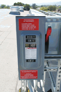
Photo 2. AC or DC disconnect?
Since jurisdictions vary in the availability of a plan review department and the time available for the inspection differ, I will not attempt to separate the items that would be accomplished at the plan review stage and those that need to be done at the on-site inspection. And, yes, I have tried many times to read a conductor size and type on a hot sweaty day when the conductors are cut to minimum length inside a disconnect—it sometimes is just not possible.
The following checklist is available on the author’s web site (see below) and it is double spaced for better readability.
CHECKLIST FOR PHOTOVOLTAIC POWER SYSTEM INSTALLATIONS
1. PV ARRAYS
-
PV modules listed to UL Standard 1703? [110.3] [690.4(D)]
a. Mechanical Attachment
-
Modules attached to the mounting structure according to the manufacturer’s instructions? [110.3(B)]
-
Roof penetrations secure and weather tight? [110.12]
b. Grounding
-
Each module grounded using the supplied hardware, the grounding point identified on the module and the manufacturer’s instructions? Note: Bolting the module to a “grounded” structure usually will not meetNECrequirements [110.3(B)]. Array PV mounting racks are usually not identified as equipment-grounding conductors. [Note 690.43(C) and (D) in 2011 have additional provisions and allowances for grounding with mounting structures.]
-
Properly sized equipment-grounding conductors routed with the circuit conductors? [690.45] Note differences between 2005, 2008 and 2011NEC.
c. Conductors
-
Conductor type? —If exposed: USE-2, UF (usually inadequate at 60°C), or SE, 90°C, wet-rated and sunlight-resistant. [690.31(B)] (2008 NEC restricts exposed single-conductor wiring to USE-2 and listed PV/Photovoltaic Wire/Cable)—If in conduit: RHW-2, THWN-2, or XHHW-2 90°C, wet-rated conductors are required. [310.15]
-
Conductor insulation rated at 90°C [UL-1703] to allow for operation at 70°C+ near modules and in conduit exposed to sunlight (add 17–20°C to ambient temperature-2005NEC)[see Table 310.15(B)(2) in the2008 NEC] [Table 310.15(B)(3)(c)]
-
Temperature-corrected ampacity calculations based on 156% of short-circuit current (Isc), and the corrected ampacity greater than 156% Isc rating of overcurrent device? [690.8,9]
Note: Suggest temperature derating factors of 65°C in installations where the backs of the module receive cooling air (4″ or more from surface) and 75°C where no cooling air can get to the backs of the modules. Ambient temperatures in excess of 40°C may require different derating factors.
(2011 690.8 substantially updates ampacity calculations to parallel calculations in other sections of theNEC.)
-
Portable power cords allowed only for tracker connections? [690.31(C), 400.3,7,8]
-
Strain reliefs/cable clamps or conduit used on all cables and cords? [300.4, 400.10]
-
Listed for the application and the environment? Fine stranded, flexible conductor cables properly terminated with terminals listed for such conductors? [690.31(E)(4)]
-
Cables and flexible conduits installed and properly marked? [690.31(E)]
-
Exposed conductors in readily accessible areas in a raceway if over 30 volts? [690.31(A)] Note: Raceways cannot be installed on modules. Conductors should be installed so that they are not readily accessible.
2. OVERCURRENT PROTECTION
-
Overcurrent devices in the dc circuits listed for dc operation? If device is not marked dc, verify dc listing with manufacturer. Auto, marine, and telecom devices are not acceptable.
-
Rated at 1.25 x 1.25 = 1.56 times short-circuit current from modules? [UL-1703, 690.8, module instructions] Note: Both 125% factors are now in theNEC, but the duplicate 125% should be removed from the modular instructions in calendar year 2011. Supplementary listed devices are allowed in PV source circuits only, but branch-circuit rated devices are preferred. [690.9(C)].
-
Each module or series string of modules have an overcurrent device protecting the module? [UL-1703/NEC110.3(B)] Note: Frequently, installers ignore this requirement marked on the back of modules. Listed combiner PV combiner boxes meeting this requirement are available. One or two strings of modules do not require overcurrent devices, but three strings or more in parallel will usually require an overcurrent device. The module maximum series fuse must be at least 1.56 Isc.
-
Located in a position in the circuit to protect the module conductors from backfed currents from parallel module circuits or from the charge controller or battery? [690-9(A) FPN, NEC-2008] Informational Note, 2011.
-
Smallest conductor used to wire modules protected? Sources of overcurrent are parallel-connected modules, batteries, and ac backfeed through inverters. [690-9(A)]
-
User-accessible fuses in “touch-safe” holders or fuses capable of being changed without touching live contacts? [690.16] Strengthened for 2011 to include distance between overcurrent device and disconnect.
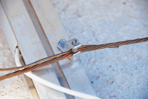
Photo 3. Double Lugging
3. ELECTRICAL CONNECTIONS
-
Pressure terminals tightened to the recommended torque specification?
-
Crimp-on terminals listed and installed with listed crimping tools by the same manufacturer? [110.3(B)]
-
Twist-on wire connectors listed for the environment (i.e., dry, damp, wet, or direct burial) and installed per the manufacturer’s instructions?
-
Pressure lugs or other terminals listed for the environment? (i.e., inside, outside, wet, direct burial)
-
Power distribution blockslistedand not just UL Recognized?
-
Terminals containing more than one conductor listed for multiple conductors?
-
Connectors or terminals using flexible, fine-stranded conductors listed for use with such conductors? [690.31(F), 690.74]
-
Locking (tool-required) on readily accessible PV conductors operating over 30 volts [690.33(C)]
4. CHARGE CONTROLLERS
-
Charge controller listed to UL Standard 1741? [110.3] [690.4(D)]
-
Exposed energized terminals not readily accessible?
-
Does a diversion controller have an independent backup control method? [690.72(B)(1)]
5. DISCONNECTS
-
Disconnects listed for dc operation in dc circuits? Automotive, marine, and telecom devices are not acceptable.
-
PV disconnect readily accessible and located at first point of penetration of PV conductors?
-
PV conductors outside structure until reaching first readily accessible disconnect unless in metallic raceway? [690.14, 690.31(F)]
-
Disconnects for all current-carrying conductors of PV source? [690.13]
-
Disconnects for equipment? [690.17]
-
Grounded conductorsnotfused or switched? Bolted disconnects OK.
Note: Listed PV Centers by Xantrex, Outback, and others for 12, 24, and 48-volt systems contain charge controllers, disconnects, and overcurrent protection for entire dc system with possible exception of source circuit or module protective fuses.
6. INVERTERS (Stand-Alone Systems)
-
Inverter listed to UL Standard 1741? [110.3] [690.4(D)] Note: Inverters listed to telecommunications or other standards do not meetNECrequirements.
-
DC input currents calculated for cable and fuse requirements? Input current = rated ac output in watts divided by lowest battery voltage divided by inverter efficiency at that power level. [690.8(B)(4)]
-
Cables to batteries sized 125% of calculated inverter input currents? [690.8(A)]
-
Overcurrent/Disconnects mounted near batteries and external to PV load centers if cables are longer than 4–5 feet to batteries or inverter?
-
High interrupt, listed, dc-rated fuses or circuit breakers used in battery circuits? AIR/AIC at least 20,000 amps? [690.71(C), 110.9]
-
No multi-wire branch circuits where single 120-volt inverters connected to 120/240-volt load centers? [100—Branch Circuit, Multi-wire], [690.10(C)]
7. BATTERIES
-
None are listed.
-
Building-wire type cables used? [Chapter 3] Note: Welding cables, marine, locomotive (DLO), and auto battery cables don’t meetNEC. Flexible, listed RHW, or THW cables are available. Article 400 flexible cables larger than 2/0 AWG are OK for battery cell connections, but not in conduit or through walls. [690.74, 400.8] Flexible, fine stranded cables require very limited, specially listed terminals. See stand-alone inverters for ampacity calculations.
-
Access limited? [690.71(B)]
-
Installed in well-vented areas (garages, basements, outbuildings, and not living areas)? Note: Manifolds, power venting, and single exterior vents to the outside are not required and should be avoided.
-
Cables to inverters, dc load centers, and/or charge controllers in conduit?
-
Conduit enters the battery enclosure below the tops of the batteries? [300.4]
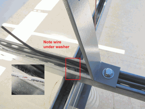
Photo 4. Undetected Ground Fault
Note: There are no listed battery boxes. Lockable heavy-duty plastic polyethylene toolboxes are usually acceptable
8. INVERTERS (Utility-Interactive Systems)
-
Inverter listed to UL Standard 1741 and identified for use in interactive photovoltaic power systems? [690.4(D), 690.60] Note: Inverters listed to telecommunications and other standards do not meetNECrequirements.
-
Backup charge controller to regulate the batteries when the grid fails? [690.72(B)(1)]
-
Connected to dedicated branch circuit with back-fed overcurrent protection? [690.64]
-
Listed dc and ac disconnects and overcurrent protection? [690.15,17]
-
Total rating of overcurrent devicessupplyingpower to ac load center (main breaker plus backfed PV breaker) must be less than load-center rating (120% of rating in residences) [690.64(B)(2)]. The2008 NECallows the 120% breaker total on commercial installations and residential system ONLY if the PV breaker is at the opposite end of the busbar from the main utility breaker. No change for 2011.
9. GROUNDING
-
Only one bonding conductor (grounded conductor to ground) for dc circuits and one bonding conductor for ac circuits (neutral to ground) for system grounding? [250] Note: The main dc bonding jumper will generally be located inside inverters as part of the ground-fault protection devices. On stand-alone systems, the dc bonding jumper may be in a separate ground-fault detection and interruption device or may be built in to the charge controller.
-
AC and dc grounding electrode conductors connected properly? They may be connected to the same grounding electrode system (ground rod). Separate electrodes, if used, must be bonded together. [690.41,47] The 2008NECin 690.47 allows a combined dc grounding electrode conductor and an ac equipment-grounding electrode, but the conditions and requirements are numerous. [690.47]. (2011NECclarifies and combines 2005 and 2008 690.47(C) requirements.)
-
The 2008NEC690.47(D) array grounding requirement was removed in 2011NEC.
-
Equipment grounding conductors properly sized (even on ungrounded, low-voltage systems)? [690.43, 45, 46]
-
Disconnects and overcurrent in both of the ungrounded conductors in each circuit on 12-volt, ungrounded systems or on ungrounded systems at any voltage? [240.20(A)], [690.41]
-
Bonding/grounding fittings used with metal conduits when dc system voltage is more than 250-V dc? [250.97]
10. CONDUCTORS (General)
- Standard building-wire cables and wiring methods used? [300.1(A)]
- Wet-rated conductors used in conduits in exposed locations? [100 Definition of Location, Wet]
- Insulations other than black in color will not be as durable as black in the outdoor UV-rich environment.
- DC color codes correct? They are the same as ac color codes—grounded conductors are white and equipment-grounding conductors are green, green/yellow, or bare. [200.6(A)] Ungrounded PV array conductors on ungrounded PV arrays willnotbe white in color.
For Additional Information
The US Department of Energy funding for providing inspectors and the PV Industry with telephone and e-mail support from the author was terminated on March 1, 2011. Answers to your questions may be delayed or not answered at all depending on future funding. Consultation services are available on a contracted basis. E-mail: jwiles@nmsu.edu Phone: 575-646-6105
See the web site below for a schedule of presentations on PV and theCode.
The Southwest Technology Development Institute web site maintains a PV Systems Inspector/Installer Checklist and all copies of the previous “Perspectives on PV” articles for easy downloading. A color copy of the latest version (1.91) of the 150-page,Photovoltaic Power Systems and the 2005 National Electrical Code: Suggested Practices, written by the author, may be downloaded from this web site: http://www.nmsu.edu/~tdi/Photovoltaics/Codes-Stds/Codes-Stds.html




Find Us on Socials