Single-phase and three-phase AC squirrel cage induction motors need some type of circuit to initiate a start or stop function. Usually single-phase motors and smaller horsepower three-phase motors can be started with full voltage across the line. However, larger horsepower three-phase motors require reduced voltage starting techniques.
Power circuits vs. Control circuits
Typically two type of circuits are used in motor control — the line voltage power circuit and the control circuit. The power circuit in full-voltage across-the-line starting consists of the overcurrent protective device (OCPD), whether fuses or circuit breaker; the line conductors that terminate on the L1, L2, and L3 terminals; the magnetic motor starter or solid-state device; and the load conductors that terminate on the T1, T2, and T3 terminals.
The control circuit consists of components of the ladder diagram — such as start and stop pushbuttons, relay coils, pilot lights, and any other variety of contact closure devices, like limit switches, pressure switches, temperature controllers, proximity sensors, or float switches. The control circuit can be further classified as two-wire or three-wire depending on the application. It is also important to note that the power circuit is sized according to the voltage rating of the motor load: 115-V, 200-V, 230-V, 460-V or 575-V. The control circuit can operate at the same voltage as the power circuit, but it can also operate at lower voltages by using a machine tool transformer to step down the voltage to safer levels.
The diagram for a typical full-voltage across-the-line starting circuit is shown in figure 1. This diagram shows both the power circuit and the control circuit. Note the control circuit is a three-wire ladder diagram control circuit, which works well for smaller horsepower three-phase motors. The electric utility will have rules for how large a motor can be started across the line. Once the horsepower of a motor exceeds that rating, reduced-voltage starting techniques must be used. Motors are inductive loads; therefore, they have very high starting currents in the range of 2.5 to 10 times the full load running current of the motor. This excessive inrush current, also called locked-rotor current, causes voltage fluctuations on the lines. You probably have observed the effect of inrush current whenever the lights in a building dip as HVAC equipment comes online. When this excessive inrush current is drawn from the voltage source for a few seconds, it causes a voltage drop. This voltage drop means a lower voltage is available to equipment; and lighting fixtures, in particular, will flicker.
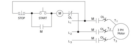
Figure 1. Full voltage three-wire control
Reduced voltage starters
There are primarily six styles of reduced-voltage starters: primary resistor, reactor, autotransformer, part-winding, wye-delta, and solid state. Solid-state reduced-voltage starters are very common as they interface well with variable frequency drives (VFDs) and programmable logic controllers (PLCs).
Primary resistor starters use resistors in series with the motor leads during the start function. Since this is now a series circuit, the applied voltage is dropped between the series resistor and the motor winding, causing a lower starting current. A timing relay operates a control relay whose contacts short the series resistors once startup is achieved.
Reactor starters operate in the same manner, except reactors are used instead of resistors. Reactor starters are far less common than they were in the past.
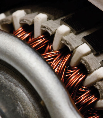
Autotransformer starters use tapped autotransformers, with taps typically set at 50%, 65% of 80% of the available line voltage. Relying on the concept of “turns ratio” in a transformer, this type of starter allows for smaller currents on the line side as seen by the electric utility and larger currents on the load side as seen by the motor during startup. An autotransformer is different from a two-winding transformer in that it does not provide electrical isolation between the primary and secondary windings. A step-up autotransformer is often called a “boosting” autotransformer, and a step-down autotransformer is called a “bucking” autotransformer.
Remember the “turns ratio” for a transformer? When looking at voltage, you rely on the following formula:
Vprimary/ Vsecondary= Nprimary/ Nsecondary
For current, you rely on this formula:
Iprimary/ Isecondary= Nsecondary/ Nprimary
Let’s take a simple example for illustration. A 1 kVA transformer has a 240-V primary and a 120-V secondary. The primary current is 4.17 A at 240 V, while the secondary current is 8.33 A at 120 V. The transformer has a 2:1 ratio. The voltage is stepped down by a factor of two, while the current is stepped up by a factor of two. This principle allows the autotransformer-type starter to operate.
The part-winding starter is designed to work with a part-winding motor that has two sets of identical windings. You can use 230/460V dual voltage motors, but you must exercise extreme caution. The concept is that the 230/460V motor operates at 230 V with the windings in parallel. Therefore, one half of the motor windings are in the circuit during startup; then a few seconds later, the other half of the motor windings are brought into the circuit. Serious problems can develop if the timing circuit does not connect the other half of the motor windings immediately after startup.
A wye-delta starter operates by allowing the motor to be started in a wye configuration and then run in a delta configuration. Utilizing this configuration allows the inrush current to be lower during the startup while still maintaining a starting torque of approximately 33%. Open transition is an important consideration to keep in mind with wye-delta starters because there will be a period of time between the wye configuration for start and the delta configuration for run when the motor windings will be disconnected. Closed transition starters overcome this disadvantage but at a much higher cost.
Solid-state starters are often called “soft start” starters because they use silicon-controlled rectifiers (SCRs) to accomplish the task. Gas-filled vacuum tubes called thyratrons were the early version of the solid-state thyristor family which includes SCRs Triacs, Diacs, and UJT (unijunction transistors). The SCR has three elements called the anode, cathode, and gate. By applying a signal to the gate element at precisely the right time, you can control how much current the SCR will either pass or block during a cycle; this is known as phase control. The ability of this device to allow either partial conduction or full conduction during a cycle offers much flexibility to the designer. This capability allows for precise control of current to a motor load during startup.
Ladder Control Circuits
The two types of ladder control circuits commonly used are the two-wire control and the three-wire control circuit. The two-wire control circuit uses maintained contact devices to control the magnetic motor starter. The three-wire control circuit uses momentary contact devices that control the magnetic motor starter.
The two-wire control circuit is shown in figure 2. It consists of a normally open maintained contact device that, when closed, energizes the coil of a magnetic motor starter, which, in turn, energizes the connected motor load. The two-wire control circuit provides what is known as “low-voltage release.” In the event of a power failure, the magnetic motor starter will drop out. Once power is restored, the magnetic motor starter will automatically re-energize, provided that none of the maintained contact devices have changed state. This can be very advantageous in applications such as refrigeration or air conditioning where you do not need someone to restart the equipment after a power failure. However, it can be extremely dangerous in applications where equipment will start automatically, placing the operator in danger.
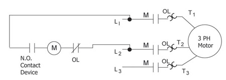
Figure 2. Full voltage two-wire control
The three-wire control circuit is shown in figure 1. It consists of a normally closed stop button (STOP), a normally open start button (START), a sealing contact (M), and the coil of a magnetic motor starter. When the normally open start button is pressed, the coil of magnetic motor starter (M) is energized. An auxiliary contact of (M) seals around the start button to provide a latched circuit. Pressing the normally closed stop button disrupts the circuit. The three-wire control circuit provides what is known as “low-voltage protection.” In the event of a power failure, the magnetic motor starter will drop out. However, in this case, once power is restored the magnetic motor starter will not automatically re-energize. The operator must press the start button to start the sequence of operations once again.
Compared to the two-wire control circuit, the three-wire control circuit provides much more safety to the operator because the machinery will not automatically start once power has been restored. Figure 3 illustrates a control circuit with multiple start and stop pushbuttons. In this circuit, multiple normally closed stop buttons are placed in series, and multiple normally open start buttons are placed in parallel to operate a magnetic motor starter. This is a common application of a three-wire control circuit in which you need to start and stop the same motor from multiple locations within the facility. The three-wire control circuit can be utilized in a variety of ways to meet specific circuit application.
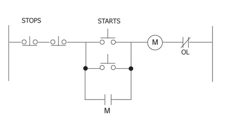
Figure 3. Multiple stop/start control circuit
AC motor control is a very interesting and specialized segment of our industry. Electromechanical magnetic motor starters have been the standard for many years. Solid-state devices have allowed for greater control of circuit parameters while allowing true integration with variable frequency drives and programmable logic controllers.



Find Us on Socials