The transformer is one of the most basic of electrical equipment found in a power distribution system, and just when you thought that a hunk of iron wound with wire couldn’t possibly be transformed, the industry does something that blows your mind. Today we’re going to take a peek into the world of transformers and learn about some recent changes in these devices that may make their application a little more complicated. We’ll explore, briefly, the topic of transformer protection and the impact that changes to this important electrical equipment has on the power distribution system.
One of the recent major innovations in the transformer is around efficiency. The most recognizable lack of efficiency in electrical equipment is what we all recognize as heat. Transformers have various types of losses; recent design changes seek to address these losses and increase efficiencies. Higher efficiency equipment reduces energy usage translating into cost savings and less burden on the power distribution system from a utility perspective. Newton told us many years ago that for every action, there is an equal and opposite reaction. This idea begs the question of the impact of raising the efficiency of a transformer.
One method transformer manufacturers use to increase efficiencies is to utilize grain-oriented steel instead of non-oriented steel. The grain-oriented steel is produced by rolling and annealing so that the steel grains are aligned in the same direction. This process minimizes the resistance to the direction changes of the magnetic flux 60 times every second and thus reduces core losses. Non-oriented steel, with grains randomly oriented, is typically used in motors and generators. Reduced impedances can have impacts on available fault currents downstream. Other important parameters are impacted as well. Before we get into these impacts, let’s get a historical perspective on this topic.
As we’ll see here, a deeper understanding of higher efficiency transformers can help in their proper application, protection, and safety. First let’s review some history and put some things into perspective.
Historical Perspectives
As a result of the Energy Policy Act of 1992, The National Electrical Manufacturers Association (NEMA) published the TP-1 standard in 1996 and updated it in 2002. It covered standard, low voltage, dry-type transformers loaded at 35% of their rating. The efficiencies in TP-1 were utilized by the Department of Energy (DOE) for the Energy Star program. This standard has been rescinded and is no longer available. This standard covered dry-type distribution transformers for single-phase, between 15 kVA and 333 kVA, and three-phase transformers between 15 kVA and 1000 kVA. See Table 1 for three-phase efficiencies.
Another reference we can’t omit is the Candidate Standard Levels (CSLs) which are used by the DOE for rating transformer efficiencies, at a 35% loading, with CSL1 having the lowest actual efficiencies, corresponding with NEMA TP-1 efficiencies and CSL5 having the highest possible calculated efficiencies. CSLs are sometimes shown as TSLs (Trial Standard Levels), with TSL1 efficiencies equal to TP-1 values. See Table 1.
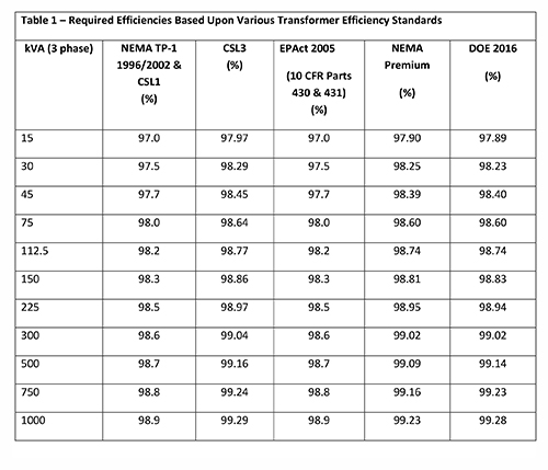
Table 1. Required Efficiencies Based Upon Various Transformer Efficiency Standard
The Energy Policy Act of 2005 (10 CFR Parts 430 & 431) utilized the NEMA TP-1 efficiency values for transformers manufactured after 1/1/2007. The efficiencies are based upon transformer loading of 35% at 75 degrees C. The Energy Policy Act covers dry-type distribution transformers for single-phase, between 15 kVA and 333 kVA, and three-phase transformers between 15 kVA and 1000 kVA. See Table 1 for three-phase efficiencies.
Introduced in 2009, with an effective date of 5/1/2010, the NEMA Premium® Efficiency standard introduced a 30% efficiency improvement over NEMA TP-1 and EPAct 2005 efficiencies. This standard addresses dry-type distribution transformers for single-phase, between 15 kVA and 333 kVA, and three-phase transformers between 15 kVA and 1000 kVA. See Table 1 for three-phase efficiencies.
Finally, on April 10, 2013, the Department of Energy introduced new, higher efficiency requirements for three-phase transformers that are based upon and very similar to the NEMA Premium Efficiency standard. Efficiencies for single-phase transformers are based upon the older TP-1 standard. These efficiencies are required for all transformers manufactured after 1/1/2016.
The above was a brief review of some history. Now that we have a little overview of the various documents and organizations involved, we can review the areas that must be considered for the proper application and protection of this equipment.
Considerations for Proper Application of High-Efficiency Transformers
Available Fault Current
The first most obvious impact of a transformer with a lower impedance value should be its potential impact on maximum available fault current. The maximum short-circuit current that can be let through by a transformer, assuming an infinite available on the primary of the transformer, is easily calculated by the following equation:

Because the transformer impedance is in the denominator, as the impedance decreases, the Isc value increases. The maximum short-circuit current for the lower efficiency (TP1) 225 kVA transformer, with an impedance of 5.7% and full load amps of 625 Amps, would be

The maximum short-circuit current for the higher efficiency 225 kVA transformer, with an impedance of 5.2% and the same full load amps, would be

In the design phase of a project, the available fault current can be addressed before equipment is installed. The challenge that can present itself to design engineers, electrical contractors, and ultimately owners is when existing transformers are replaced with higher efficiency transformers and the available fault current for downstream equipment is increased. Increased fault currents in existing systems places existing equipment at risk of having ratings such as interrupting ratings and short-circuit current ratings exceeded negatively impacting safety. Proper consideration must be made for overcurrent protective devices and industrial control equipment that carry these types of ratings.
Interrupting ratings (NEC® 110.9)
Section 110.9 of the NEC requires that overcurrent protective devices have an interrupting rating equal to or greater than the available short-circuit current. The difference between the impedance of the CSL3 transformer and the TP1 transformer is enough possibly to violate Section 110.9 of the NEC and place equipment at risk of exceeding its rating. For our example, assume the 225 KVA transformer is supplying a 600-ampere panelboard through 350 kcmil 75 degrees C copper conductors, two per phase. These conductors have an ampacity of 310 amperes each, for a total of 620 amperes. With this in mind, the overcurrent protective device on the secondary would likely be reduced to 600 amperes, which would provide protection for the secondary of the transformer, the two 350 kcmil conductors per phase and the 600-ampere panelboard.
Assuming 50 feet of the 350 kcmil conductors in steel conduit, with no motor load, the fault current from the TP1 transformer can be calculated to approximately 9,820 amperes. This calculation would typically result in equipment selection with a 10,000-ampere interrupting rating to be utilized. For this same set-up, with the higher efficiency transformer, the available fault current would be approximately 10,659 amperes creating a hazard if 10 kA interrupting rated equipment is used. This situation can present a challenge for existing installations where transformers are changed.
Short-Circuit Current Ratings (NEC 110.10)
A short-circuit current rating is the most current that equipment can let pass through it under short-circuit conditions without being extensively damaged, according to standard test conditions. This is different than an interrupting rating, which is the maximum short-circuit current that an overcurrent protective device can safely clear without extensive damage to itself, according to standard test conditions. Section 110.10 requires that equipment and components have a short-circuit current rating that is sufficient for the maximum available short-circuit current. Section 409.22 requires that industrial control panels have a short-circuit current rating that is equal to or greater than the maximum available short-circuit current. Section 670.5 has a similar requirement for industrial machinery. The greater available short-circuit current let through by higher efficiency transformers could make a difference as far as short-circuit current ratings are concerned if the higher available short-circuit current exceeds the equipment short-circuit current rating.
Inrush currents
Another possibly not so obvious impact to the installation is the inrush current for a transformer. A three-phase 225 KVA transformer with 480-volt primary and 120/208-volt secondary that meets the TP1 requirements might have an absolute maximum inrush of 2,490 amperes; 9.2 times the 270-ampere primary current. That same size transformer built to the CSL3 requirements has an absolute maximum inrush current of 2,686 amperes; a factor of 9.9 times the 270-ampere primary current. The absolute maximum inrush is the maximum inrush that could occur the first time a transformer is energized. After a transformer has been energized, it will have retained at least some of the magnetic flux in the core, resulting in much lower inrush currents in the future. Manufacturers also provide “practical” maximum inrush currents, which will be about 1/3 of the absolute maximum inrush currents. The TP1 transformer has a practical maximum inrush current of 830 amperes; a factor of 3.1 times the full load amps. The higher efficiency CSL3 transformer has a practical maximum of 895 amperes; a factor of 3.3 times the full load amps.
Inrush currents must be considered when selecting line side overcurrent protective devices to ensure they do not open upon energizing the transformer. NEC 450.3 provides the requirements for sizing the overcurrent protective devices for transformers. It provides the maximum OCPD size for various conditions such as
- When primary protection is the only protection provided
- When primary and secondary protection is provided
Considering this for the previous example of a 225 KVA transformer, Section 450.3 would limit a primary-protection-only device to 125% of the 270 full load amperes (337.5 amperes) or the next standard size OCPD, which happens to be 350 amperes.
The lower efficiency TP1 transformer absolute maximum inrush would be approximately 2490/350 = 7.1 times the ampere rating of a 350-ampere fuse or circuit breaker. It would likely open a 350-ampere non-time delay fuse and may be enough to trip a 350-amp circuit breaker or open a 350-ampere time delay fuse. For the higher efficiency transformer, the absolute maximum inrush would be about 2686/350 = 7.7 times the ampere rating of the overcurrent protective device. Again, it would likely open the non-time-delay fuse, and the chances of tripping the circuit breaker or opening the time-delay fuse are now even greater.
For both primary and secondary protection, Section 450.3 would allow the primary overcurrent protective device to be as high as 250% of the 270 full load amperes (675 amperes), or the next lower size which would be 600 amperes. For the lower efficiency transformer, that would be 2490/600 or 4.2 times the rating of the overcurrent device and shouldn’t cause a problem with nuisance opening of either circuit breakers or fuses. Section 450.3 would limit the secondary protection at 125% of the 625-ampere secondary full load current (781 amperes) or the next larger size (if 125% does not correspond with a standard size) which is an 800 ampere OCPD. This 800-ampere secondary circuit breaker or fuse does not “see” the inrush current and so would not be affected.
Should the 350-ampere overcurrent protective device open on inrush, both primary and secondary protection will be required permitting sizing of the primary OCPD up to 600 amperes. It should be quite obvious that a lower current rated OCPD would provide a higher degree of equipment protection than the higher rated OCPD device. Higher current ratings can result in longer clearing times of arcing currents which will impact incident energy values.
Designing for safety
Higher efficiency transformers are now mandated by law and special considerations for the design should be considered for safety. Solutions exist from many manufacturers to address design and safety concerns. The following are some examples that could be considered. This list represents a sample of options available. It is not meant to be an all-inclusive list.
- Primary OCPD protection
Higher efficiency transformers have a higher inrush current. The use of circuit breakers with an adjustable instantaneous trip or the use of time-delay fuses may be sufficient to overcome the increased inrush current from the higher efficiency transformers. However, if the arcing current is now below the instantaneous trip of the circuit breaker or the current limiting threshold of the current limiting fuses, the incident energy will increase.Where an adjustable instantaneous trip for a circuit breaker or time-delay for a fuse isn’t enough to handle the extra inrush, larger sized overcurrent devices are needed. While they may be able to handle the inrush, the larger devices may present higher incident energy values as previously described. - Current limitation
When the available short-circuit current exceeds the short-circuit current rating of equipment or interrupting ratings of OCPDs, two techniques can be leveraged that directly relate to reducing the available fault current. Current limitation can also help in reducing incident energy.
- It may be possible to increase the short-circuit current rating of the equipment by simply changing out the overcurrent protective device protecting the equipment, assuming the equipment marking allows for the increased rating.
- An isolation transformer can also be placed ahead of the inadequately rated equipment, reducing the available short-circuit current to which the equipment can be exposed.
- Reducing incident energy
There are numerous available techniques that can be designed-in to reduce the incident energy to which an employee might be exposed. These technologies are included as options to meet the requirements of Section 240.87 found in NEC 2014.
Arc Reduction Maintenance Switch
An arc reduction maintenance switch (ARMS) is a switch on circuit breakers that a worker turns on when preparing to work on or near energized equipment/conductors. When turned “on” the adjustable settings for time and current are turned down to minimum, so that the circuit breaker will open just as fast as possible should an arc-flash occur. When the employee finishes working on or near the energized equipment/conductors, he or she turns the ARMS off.
Zone Selective Interlocking
Zone Selective Interlocking (ZSI) allows an upstream circuit breaker to communicate with a downstream circuit breaker. For short-circuits on the load side of the downstream circuit breaker, the downstream circuit breaker sends a restraining signal to the upstream circuit breaker allowing it to utilize its time delay settings to maximize the coordination between the two. For short-circuits between the upstream circuit breaker and the downstream circuit breaker, the downstream circuit breaker does not “see” the short-circuit, so it cannot send a signal to the upstream circuit breaker. Without a restraining signal from the downstream circuit breaker, the upstream circuit breaker will open as quickly as possible. Thus, for an arcing fault between the two devices, the incident energy to which an employee would be exposed is minimized.
Active Mitigation System
The active mitigation system is best described in Informational Note No. 2 to NEC 240.87(B) which explains that this equipment helps reduce arcing duration in the electrical distribution system. This process is an active technology that is on watch 24-7-365.
Differential Relaying
Differential relaying measures currents going into and out of a zone, a switchboard or motor control center. If the current going into the zone does not equal the current coming out of the zone a trip signal is sent and the fault is cleared without an intentional delay. Differential relaying reduces the incident energy to which an employee could be exposed by opening for short-circuits of predetermined levels within the equipment.
Closing Remarks
The use of higher efficiency transformers is being required by law. Along with the higher efficiencies, the transformers (1) have higher inrush currents, that can cause overcurrent devices to nuisance open, and (2) have lower impedances that result in higher available short-circuit currents. Solutions to both the nuisance opening and the higher available short-circuit currents have been described in detail. Incident energies can also increase as a result of utilizing the higher efficiency transformers, but those higher incident energies can also be mitigated. Numerous arc-flash incident energy mitigation techniques have been provided.




Find Us on Socials