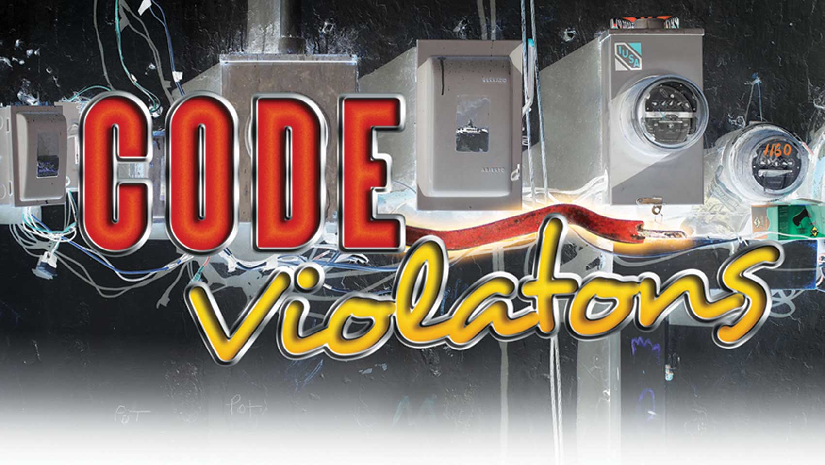
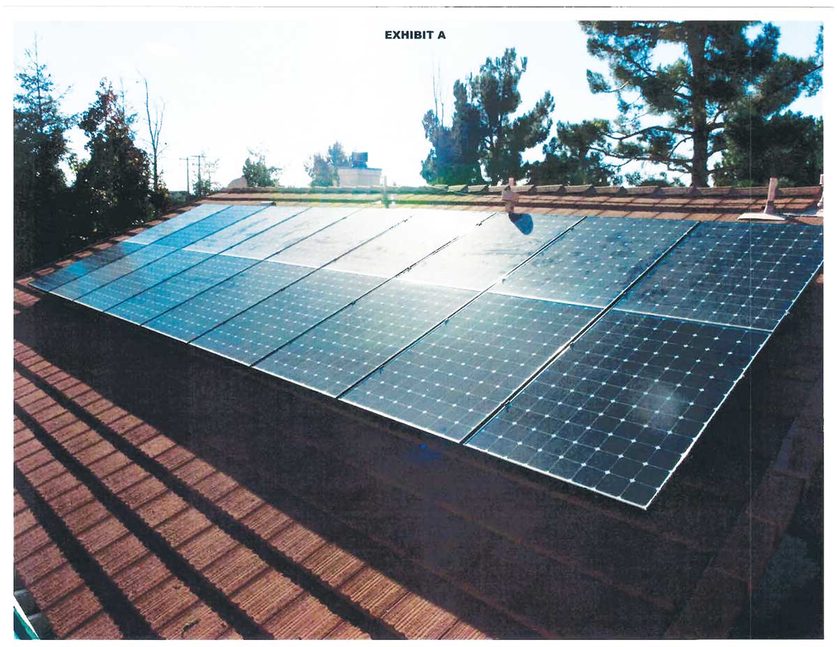
The two PV arrays originally consisted of 32 roof-mounted 327-watt modules, arranged in 4 strings of 8 modules. See exhibits “A” and “B.” The arrays were connected to a 10 kW inverter located on the exterior of the house adjacent to a 120/240 V, 125-amp dedicated PV panelboard. The utility-interactive inverter contained dc arc-fault and ground-fault protective circuitry in accordance with the 2013 California Electrical Code (CEC) [2011 NEC with amendments] and UL 1741 requirements. The existing electrical service was upgraded under the same permit to a 200-amp panelboard with a 175-amp main circuit breaker to allow integration of the 60-amp inverter circuit breaker in accordance with CEC 705.12(D).
The module open-circuit voltage (Voc) is 64.9 Vdc at Standard Test Condition (STC). The low-temperature open-circuit string voltage for an eight module string is 582 Vdc. Module and source/output short-circuit current (lsc) is 6.46 amps. The array dc source conductors (strings) were not combined prior to the inverter. The fused positive and negative dc input terminal block of the inverter allowed for up to six inputs.
A #10 copper equipment grounding conductor was installed with the array output conductors to the inverter. Bonding of the array racks and modules was in accordance with the manufacturer’s installation instructions.
Type PV conductors (#10 AWG) were used as exposed source conductors under the array. The exposed Type PV conductors were spliced to #10 THWN/THHN conductors within an exterior junction box located under each array. A ¾” flexible metal conduit (FMC) was installed from each of the two junction boxes to a single junction box located in the attic. All dc output (string) conductors were routed through a single 1″ FMC conduit from the attic junction box to the inverter. The 1″ FMC transitioned to 1″ electrical metallic tubing (EMT) before exiting the attic. The inverter was equipped with an integral dc disconnect.
The inverter (ac) output supplied an adjacent 120/240 V, 125-amp dedicated PV panelboard through three #6 cu. conductors connected to a two-pole, 60-amp circuit breaker. The PV panelboard connected to the 120/240 V, 200-amp service with #6 feeder conductors and to a 60-amp, two-pole circuit breaker located in the service panelboard. A #8 grounding electrode conductor/equipment grounding conductor was installed with the feeder conductors.
The attachment/flashing inspection was approved on 2/11/2014. The service release for the upgraded service panelboard was approved on 2/26/2014, and the final inspection was scheduled for 2/27/2014. There were no deviations from the approved plan nor were code violations evident, and the installation was approved.
The Addition
In an effort to increase the production of the system, the original contractor installed additional modules in October 2015. No permit was obtained to perform the work.
Four new 327-watt modules were added to the two existing arrays. Two of the modules were added to the East array and two to the West array. The four new modules were connected together in a single isolated string with an open-circuit voltage of 291 Vdc (low temperature) and a short-circuit current of 6.46 amps. Type PV conductors were used as the exposed array conductors and were spliced to #10 THHN/THWN conductors in one of the same roof-mounted junction boxes used for the original array(s). The two new array output conductors were pulled through the existing ¾” and 1″ FMC/EMT used for the original array output conductors and connected to the inverter through unused positive and negative input terminals
The Fire
The installation was completed on October 23, 2015, and, according to the homeowner, the PV system would no longer operate correctly. The installer returned on November 5 to correct the problem. The homeowner was observing the installer while he attempted to change a fuse for the added string conductors and saw a large arc as the fuse was removed. The arc ignited a fire within the inverter.
The inverter integral dc disconnect was opened in an attempt to stop the dc current flow to the burning inverter.
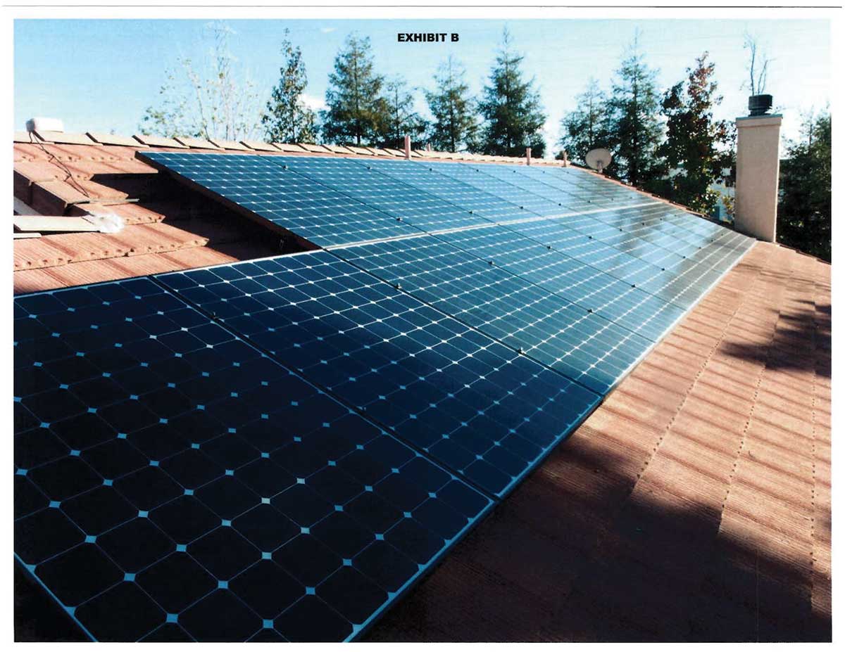
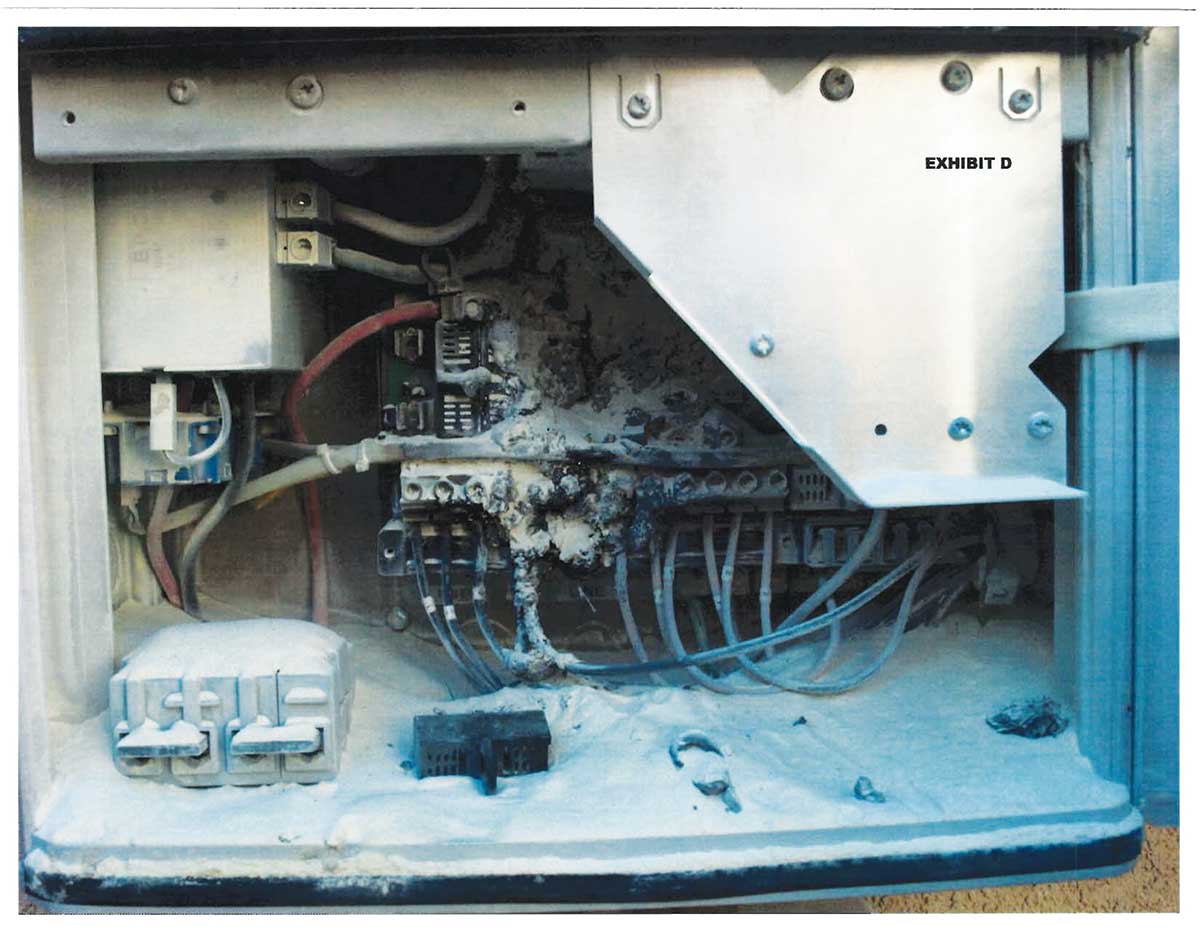
The design of the integral dc disconnect did not isolate the inverter until after the connection where the five pairs of array output (string) conductors were combined within the inverter. The arc and resulting fire involved the conductors and circuitry on the line (array) side of the disconnect switch. Opening the switch did not stop the current flow from the array to the burning inverter. See exhibits C and D.
An available fire extinguisher was used in an attempt to put out the fire, but the attempt was unsuccessful, and the inverter continued to burn. The fire department was notified at 12:24 pm and arrived at 12:29 pm.
According to the first responder incident report: “After investigating, we determined that we have to get the solar panels disconnected in order to extinguish the fire. The employee from the solar company along with 61 crew were able to disconnect the panels thus extinguishing the fire.”
The inverter was destroyed, but the fire was extinguished before it could spread to the exterior of the home. The PV module array and electrical service panel were not damaged.
A possible cause of the fire was the incorrect polarity of the added dc array conductors (inverter input).
According to the inverter manufacturer: “Reverse polarity of solar module strings can lead to an unacceptable overload condition. This can cause a strong arc, which can lead to an inverter fire. When using string fuses or combiner dc bus bars, always make sure that the polarity is correct before connecting the individual solar module strings.”
Connection of a single module string in the opposite polarity of the other connected strings could result in a doubling of the open-circuit voltage at the fuse holder. Removal or installation of the fuse could result in a dc arc. The dc output conductors installed from the array to the inverter are color-coded for polarity. The exposed Type PV array conductors are not. Color coding is not required by the California Electrical Code for the exposed array conductors.
Removal of array modules and inspection of the added source string conductors did confirm a reverse polarity connection.
Corrective Items
- A new permit for the repair of the PV system is required.
- The revised PV plan must be submitted to the Building Department for review and approval.
- A final inspection will be required under the new permit.
Epilog
The installer violated basic electrical safety, product and code rules jeopardizing his own safety and resulting in the inverter involved fire. The violations include:
- Incorrect termination of the dc source conductors (polarity)
- Working with energized conductors
- Energized conductors present with the inverter cover open
Existing NEC rules require that “The installation of equipment and all associated wiring and interconnections shall be performed only by qualified persons” [NEC 690.4(C)]. The term “Qualified Person” is defined by NEC Article 100 as “One who has the skills and knowledge related to the construction and operation of the electrical equipment and installations and has received the safety training to recognize and avoid the hazards involved.”
As this incident clearly demonstrates, the use of qualified personnel (including electrical inspectors) is essential for the safe installation of electrical systems.