With close to 500 authorities having jurisdiction (AHJs) in the state of California alone, it is often difficult to keep track of the preferential building requirements for each governing office. For example, regarding photovoltaics over the last decade, there seems to be a great deal of confusion as to the requirements of AC disconnects. The confusion stems from electric code evolution, manufacturer suggestions, fire department preference, utility regulations for grid interconnection, and common misinterpretation of the code language and intent.
All of which result in difficulty for the AHJ’s requirements and contractor installation procedures to stay up-to-date. The purpose of this article is to inform, educate, and offer guidance in properly identifying when an AC disconnect is required for a residential or small commercial PV installation.
UL 1741, IEEE 1547, “anti-islanding” protection
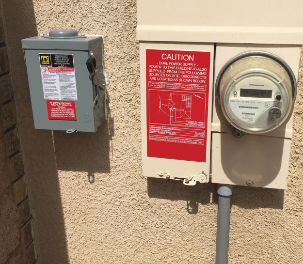
Since disconnecting means deal directly with safety concerns, there is an element of extra caution from many inspectors who are unfamiliar with PV requirements. This caution can result in non-standard requested installation practices from AHJs that are not only unnecessary and costly but also confusing to first responders. It shall be noted that as a backup safety for linemen and first responders, grid-tied inverters (GTIs) currently being sold in the United States must meet anti-islanding protection. When grid power is lost, or the voltage or frequency drifts outside operational parameters, the device will cease system output to the utility. This is noted by the interconnection standards of IEEE 1547, and UL 1741.
The purpose of disconnecting means
When requiring a disconnecting means, it is important to understand the purpose of that specific disconnect. Per the California Electrical Code, v2016, Disconnecting Means is defined as, “a device, or group of devices, or other means by which the conductors of a circuit can be disconnected from their source of supply. It stands then, that an AC disconnect is defined as, a device, or group of devices, or other means by which the AC conductors of a circuit can be disconnected from their source of supply.” Also known as the electrical infrastructure and equipment from the utility connection onsite to the inverter(s). The three most commonly cited requirement categories for AC disconnect placement are the following: equipment service, safety for firefighters, and utility operation.
The first of which is the California Electrical Code. Nearly all the requirements for AC disconnecting means can be found in Articles 690 and 705. The articles discuss type, location, and purpose of the disconnect.
California Electrical Code (v2016) Article 690: Solar Photovoltaic (PV) Systems
It shall be noted that the requirements in Section 690.13 Building or Other Structure Supplied by a Photovoltaic System only apply to disconnecting means for DC ungrounded conductors.
690.15 Disconnection of Photovoltaic Equipment.
Means shall be provided to disconnect equipment, such as inverters, batteries, and charge controllers, from all ungrounded conductors or all sources. If the equipment is energized from more than one source, the disconnecting means shall be grouped and identified.
A single disconnecting means in accordance with 690. 17 shall be permitted for the combined ac output of one or more inverters or ac modules in an interactive system.
(A) Utility-Interactive Inverters Mounted in Not Readily Accessible Locations. Utility-interactive inverters shall be permitted to be mounted on roofs or other exterior areas that are not readily accessible and shall comply with 690.15(A)(1) through (4):
(1) A dc PV disconnecting means shall be mounted within sight of or in each inverter.
(2) An ac disconnecting means shall be mounted within sight or in each inverter.
(3) The ac output conductors from the inverter and an additional ac disconnecting means for the inverter shall comply with 690.13(A).
(4) A plaque shall be installed in accordance with 705.10
690.17 Disconnect Type.
(A) Manually Operable. The disconnecting means for ungrounded PV conductors shall consist of a manually operable switch(es) or circuit breaker(s). The disconnecting means shall be permitted to be power operable with provisions for manual operation in the event of a power-supply failure. The disconnecting means shall be one of the following listed devices:
(1) A PV industrial control switch marked for use in PV systems.
(2) A PV molded-case circuit breaker marked for use in PV systems.
(3) A PV molded-case switch marked for use in PV systems.
(4) A PV enclosed switch marked for use in PV systems.
(5) A PV open-type switch marked for use in PV.
(6) A dc-rated molded case circuit breaker suitable for backfeed operation.
(7) A dc-rated molded-case switch suitable for backfeed operation.
(8) A dc-rated enclosed switch.
(9) A dc-rated open-type switch.
(10) A dc-rated rated low-voltage power circuit breaker.
Informational Note: Devices marked with “line” and “load” are not suitable for back feed or reverse current.
(B) Simultaneous Opening of Poles. The PV disconnecting means shall simultaneously disconnect all ungrounded supply conductors.
(C) Externally Operable and Indicating. The PV disconnecting means shall be externally operable without exposing the operator to contact with live parts and shall indicate whether in the open or closed position.
(D) Disconnection of Grounded Conductor. A switch, circuit breaker, or other device shall not be installed in a grounded conductor if operation of that switch, circuit breaker, or other device leaves the marked, grounded conductor in an ungrounded and energized state.
Exception No. 1: A switch or circuit breaker that is part of a ground-fault detection system required by 690.5, or that is part of an arc-fault detection/interruption system required by 690.11, shall be permitted to open the grounded conductor when that switch or circuit breaker is automatically opened as a normal function of the device in responding to ground faults.
Exception No. 2: A disconnecting switch shall be permitted in a grounded conductor if all the following conditions are met:
(1) The switch is used only for PV array maintenance.
(2) The switch is accessible only by qualified persons.
(3) The switch is rated for the maximum dc voltage and current that could be present during any operation, including ground-fault conditions.
(E) Interrupting Rating. The building or structure disconnecting means shall have an interrupting rating sufficient for the maximum circuit voltage and current that is available at the line terminals of the equipment. Where all terminals of the disconnecting means may be energized in the open position, a warning sign shall be mounted on or adjacent to the disconnecting means.
Exception: A connector shall be permitted to be used as an ac or a dc disconnecting means, provided that it complies with the requirements of 690. 33 and is listed and identified for use with specific equipment.
690.15— 690.17 Confusion within the code
There are two portions of this code section that commonly cause confusion. The first being the statement, “A single disconnecting means in accordance with 690.17 shall be permitted for the combined ac output of one or more inverters or ac modules in an interactive system.” However, it should be noted that since 690.17(A) refers to dc-rated equipment specifically, it follows that this section does not apply to AC disconnecting means. The “listed devices” addition may have been an oversight since 690.15 still references 690.17 for AC disconnecting means from the previous code cycle. This section has been further amended drastically in NEC 2017 to assist in clearing up confusion. For the time being, AHJs may bypass the list and allow disconnecting means that meet the current other requirements.
Second, 690.15(A)(2) often encourages those unfamiliar with UL standards to install or require a roof-mounted, externally operable AC disconnect for micro-inverter systems. Most micro-inverter brands have amended their AC connectors on the cables to comply with requirements to be labeled a disconnecting means through 690.17(A-E)’s “Exception.” It is important to realize that though placed after 690.17(E), the exception does, in fact, apply to 690.17(A-E). This is recognized by both the National Fire Protection Association (NFPA), as well as the California Building Standards Commission (CBSC).
California Electrical Code (v 2016)
Article 705: Interconnected Electric Power Production Sources
705.12 Point of Connection. The output of an interconnected electric power source shall be connected as specified in 705.12(A), (B), (C), or (D).
(D) Utility-Interactive Inverters. The output of a utility-interactive inverter shall be permitted to be connected to the load side of the service disconnecting means of the other source(s) at any distribution equipment on the premises. Where distribution equipment, including switchgear, switchboards, or panelboards, is fed simultaneously by a primary source(s) of electricity and one or more utility-interactive inverters, and where this distribution equipment is capable of supplying multiple branch circuits or feeders, or both, the interconnecting provisions for the utility-interactive inverter(s) shall comply with 705. 12(D)(1) through (D)(6).
(1) Dedicated Overcurrent and Disconnect. The source interconnection of one or more inverters installed in one system shall be made at a dedicated circuit breaker or fusible disconnecting means. …
(4) Suitable for Backfeed. Circuit breakers, if backfed, shall be suitable for such operation.
Informational Note: Fused disconnects, unless otherwise marked, are suitable for backfeeding.
705.20 Disconnecting Means, Sources. Means shall be provided to disconnect all ungrounded conductors of an electric power production source(s) from all other conductors.
705.21 Disconnecting Means. Means shall be provided to disconnect power production equipment, such as utility interactive inverters or transformers associated with a power production source, from all ungrounded conductors of all sources of supply. Equipment intended to be operated and maintained as an integral part of a power production source exceeding 1000 volts shall not be required to have a disconnecting means.
705.22 Disconnect Device. The disconnecting means for ungrounded conductors shall consist of a manually or power operable switch(es) or circuit breaker(s) with the following features:
(1) Located where readily accessible.
(2) Externally operable without exposing the operator to contact with live parts and, if power operable, of a type that could be opened by hand in the event of a power-supply failure.
(3) Plainly indicating whether in the open (off) or closed (on) position.
(4) Having ratings not less than the load to be carried and the fault current to be interrupted. For disconnect equipment energized from both sides, a marking shall be provided to indicate that all contacts of the disconnect equipment might be energized.
Informational Note: In parallel generation systems, some equipment, including knife blade switches and fuses, is likely to be energized from both directions. See 240. 40
(5) Simultaneous disconnect of all ungrounded conductors of all grounded conductors of the circuit.
(6) Capable of being locked in the open (off) position.
705.30 Overcurrent Protection. Conductors shall be protected in accordance with Article 240. Equipment and conductors connected to more than one electrical source shall have a sufficient number of overcurrent devices located so as to provide protection from all sources.
(A) Solar Photovoltaic Systems. Solar photovoltaic systems shall be protected in accordance with Article 690.
705.31 Location of Overcurrent Protection.
Overcurrent protection for electric power production source conductor, connected to the supply side of the service disconnecting means in accordance with 705. 12(A), shall be located within 3 m (10 ft) of the point where the electric power production source conductors are connected to the service.
Informational Note: This overcurrent protection protects against short-circuit current supplied from the primary source(s) of electricity.
Exception: Where the overcurrent protection for the power production source is located more than 3 m (10 ft) from the point of connection for the electric power production source to the service, cable limiters or current-limited circuit breakers for each ungrounded conductor shall be installed at the point where the electric power production conductors are connected to the service.
705.70 Utility-Interactive Inverters Mounted in Not-Readily-Accessible Locations.
Utility-interactive inverters shall be permitted to be mounted on roofs or other exterior areas that are not readily accessible. These installations shall comply with (1) through (4):
(1) A direct-current disconnecting means shall be mounted within sight of or in the inverter.
(2) An alternating-current disconnecting means shall be mounted within sight of or in the inverter.
(3) An additional alternating-current disconnecting means for the inverter shall comply with 705.22.
(4) A plaque shall be installed in accordance with 705.10.
705.12 — 705.22 Confusion within the industry
This section of code specifically addresses interconnection of a PV system to a panelboard by breakers or fuses, the requirements of backfeeding, and overcurrent protection. There is still a great deal of ambiguity of this section of code within the AHJ and photovoltaic community. It shall be noted that a dedicated inverter output breaker located within a panel board, can be utilized, and is compliant so long as it meets the requirements listed in both 690.17 and 705.22.
There is also common confusion regarding enclosures of panelboards being compliant with 705.22(6) “Capable of being locked in the open (off) position.” It is important to note that the current NEC handbook addresses this concern with the following statement: “The means to lock the switch or circuit breaker in the open position must be an integral part of the enclosure or be an accessory that is not readily removed from the switch or circuit breaker.”
AC Disconnect Requirements for Fire Safety
Safety concerns for Fire staff disconnecting the ac conductors of a photovoltaic systems has expanded to include dc conductors as well. Though pulling the meter and switching breakers to the off position are still effective means of ac disconnection, the dc lines are still energized. This was addressed with the addition of the improved 690. 12.
690. 12 Rapid Shutdown of PV Systems on Buildings.
PV system circuits installed on or in buildings shall include a rapid shutdown function that controls specific conductors in accordance with 690. 12(1) through (5) as follows.
(1) Requirements for controlled conductors shall apply only to PV system conductors of more than 1. 5 m (5 ft) in length inside a building, or more than 3 m (10 ft) from a PV array.
(2) Controlled conductors shall be limited to not more than 30 volts and 240 volt-amperes within 10 30* seconds of rapid shutdown initiation.
(3) Voltage and power shall be measured between any two conductors and between any conductor and ground.
(4) The rapid shutdown initiation methods shall be labeled in accordance with 690. 56(C).
(5) Equipment that performs the rapid shutdown shall be listed and identified.
*690. 12(2), TIA 14-10, 8. 16. 16
Revise 690. 12(2) to read as follows: (2) Controlled conductors shall be limited to no more than 30 volts and 240VA within 30 seconds of rapid shutdown initiation.
AC Disconnect Requirements for Utilities
Since the introduction of UL 1741, none of the three utilities that make up the California Public Utilities Commission require an additional external operable disconnect device for PV interconnection provided the distributed generation (DG) is compliant to the utility’s guidelines.
PG&E’s Current Stance
Installing AC disconnect switches for inverter-based generation systems.
PLEASE NOTE: You are not required to include an AC Disconnect Switch when your facility has a single-phase, self-contained electric revenue meter. A 0-320-amp panel is an example of this type of meter, which is used by 98 percent of our customers.
Distribution Interconnection Handbook: Exemption to the Disconnect Switch installation requirement.
Applicants with inverter-based generating systems that are supplied by PG&E single phase services up to 240 volts may be exempted from installing a disconnect switch, as determined by PG&E, if the meter panel that is interconnected with the generation source(s) meets all the following conditions:
- Self-contained (not transformer-rated).
- Accepts socket-based meters (not bolt-on meters).
- Rated for 320 amps or less of “continuous” current.
- Single-phase, 120/240 volt or 120/208 volt.
SCE’s Current Stance
Visible Open AC Disconnect Switch requirements for generation interconnection to distribution voltages 34. 5kV or below.
Per SCE guidelines, a single visibly open, lockable AC Disconnect is required for all for the following aggregate generating facilities:
- All Commercial
- All Residential Non-Self-Contained Meters
- All Line-Side Taps (additional overcurrent protection required)
- All Generation Meter Adapter applications
Self-Contained Meter with One Main Switch (Circuit Breaker, CB)
For these facilities, SCE can utilize the SCE revenue meter to disconnect the generation and load from the SCE Distribution System . . . To use this option, the following requirements must be met:
- Facility must have a main breaker that can be operated by the customer on the same metering switchboard (meter panel) as the revenue meter.
- Customer must agree that when it is necessary to disconnect the generating facility by opening the main CB and then removing the revenue meter, the customer will also experience an outage to the customer’s facility until the meter is reinstalled.
SDG&E’s Current Stance
Effective January 01, 2010, customers installing inverter-based systems will no longer be required to include an AC disconnect switch when the facility has a self-contained electric revenue meter (i.e., 0-320-amp socket-based meters or 400-amp K-based meters). This type of meter is used by the vast majority of all SDG&E.
References
2016 California Electrical Code, Title 24, Part 3 (2016).
NEC 2014 Handbook, 1st Edition, NFPA (2014).
Tentative Interim Amendment, NFPA, http://www.nfpa.org/assets/files/AboutTheCodes/70/TIA_70_14_10.pdf (last visited Mar 16, 2017)
Tentative Interim Amendment, NFPA, https://www.documents.dgs.ca.gov/bsc/Info-Bulletins/BSC-BULLETIN-16-02-CEC-TIA-FINAL-REV.pdf (last visited Mar 16, 2017)
Installing AC Disconnect Switches for Inverter-based Generation Systems, PG&E, https://www. pge. com/en_US/for-our-business-partners/interconnection-renewables/export-power/ac-disconnect-switches-for-inverter-based-generation/ac-disconnect-switches-for-inverter-based-generation. page (last visited Mar 2, 2017).
Interconnection Handbook, SCE — Net Metering (2016), https://www.sce.com/wps/wcm/connect/7b9d71b0-bb05-4a41-8d63-483a6469ecdd/NEM Interconnection Handbook August 2016 final.pdf?MOD=AJPERES (last visited Mar 2, 2017).
Apply for NEM — Requirements, SDGE, http://www.sdge.com/clean-energy/apply-nem/apply-nem-requirements (last visited Mar 2, 2017).