This is the second of a series of articles detailing significant changes for the 2021 Canadian Electrical Code Part I (CE Code). A full copy of the CE Code is available at https://www.csagroup.org/store/.
Section 12
The first change in Section 12 is a clarification in Rule 12-010 5) adding “in accordance with Rules 2-130 and 2-132” to the wiring methods mandated in a furnace cold-air return duct that is formed by boxing in between joists of a combustible building. This change in Subrule 5) highlights the existing building code requirement that the cable which runs inside an air plenum in a combustible building must be marked FT6.
The second change in Section 12 can be found in Rule 12-020 Wiring under raised floors for data processing and similar systems. Liquid-tight flexible conduit as a wiring option was removed as redundant wording as recent changes in Rule 12-1302 allow liquid-tight flexible conduit to be used as a general wiring method. The major change to Rule 12-020 is to allow portable power cable not exceeding 4.5 m in length to be used as a wiring method under raised data processing floors. In addition, cables passing through raised data processing floors must now terminate directly into the bottom of the data processing equipment.
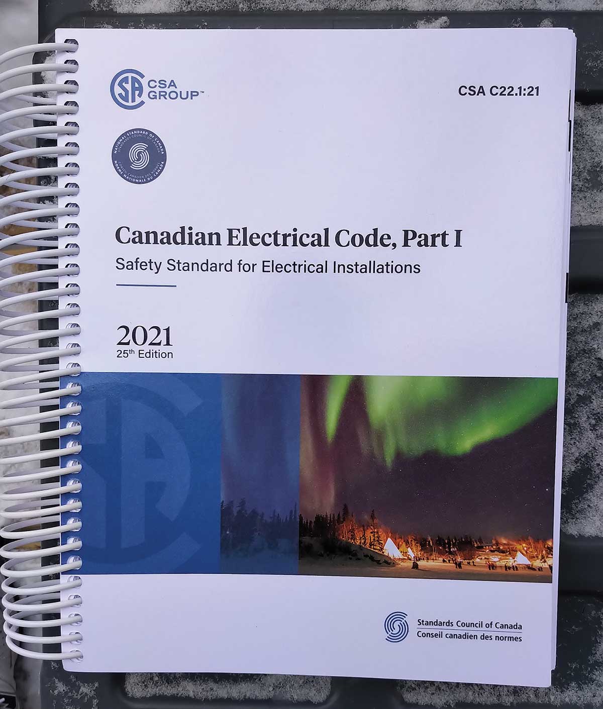
New Rule 12-022 Cables or raceways installed in roof decking systems no longer allows cables or raceways to be concealed within a roof decking system where the roof systems utilise screws or other metal penetrating fasteners.
Where the roof decking system does not utilize screws or other metal penetrating fasteners like adhesives, this new rule would not apply. In addition, Subrule 2) allows concealed Class 2 wiring in which the open-circuit voltage does not exceed 30 V and embedded trace heat. Where Class 2 circuits and embedded trace heat wiring is concealed within a roof system that utilises screws or other metal penetrating fasteners warning labels will also be required in a conspicuous location in the roof area where the cabling is installed and at all permanently installed roof access points.
Rule 12-100 and 12-102 were reworded, removing duplication and aligning with a completely new Table 19.
Table 19 was first introduced into the CE Code in the Sixth Edition Published in 1953. The first Table 19 was an expansion of Table 1 from the 1947 CE Code that was limited to Conductor Designation, Type, and Maximum Allowable Temperature. In 1953, Table 19 reference rules in Sections 12 only. In the 1958 CE Code, Table 19 was expanded to include Conditions of Use and Trade Designation and to include rule references for Sections 4, 12, 16, 22, 26, 34, 36, and 38.
Over the years, more references were added as the table grew, resulting in the table referencing seventeen sections of the code in the 2009 Edition. Between the 2009 and 2018 Editions of the CE Code, rule references were moved to Section 12. This change gave Section 12 the responsibility to maintain Table 19. For the 2021 CE Code development cycle, a task group was established by the Section 12 Chair. This task group met once a month over eighteen months to develop a new Table 19. The new Table 19 similar to the structure of Table 65 now. It is easier to use, accurate, smaller, and has no notes. The task group reviewed each insulated conductor and cable type for accuracy and missing types and applications. In addition, all 37 notes were removed. Some of the notes were moved to rules in the body of the code, some were moved to Appendix B notes, and the rest were deleted as out-of-date references. One great outcome is that all the information for any one type of insulated conductors or cables is located on a single page, making the table much easier to use.
As an example, all information for insulated conductors (like RW90) can be found on the first page of the new Table 19. Table 19 now has eight pages as follows.
- Thermoset insulated conductor, Thermoset cable, Thermoplastic insulated conductor, and Thermoplastic cables
- Non-metallic sheathed cable, and Cables not having a metal armour or metal sheath
- Cables not having a metal armour or metal sheath, and Extra-low voltage cables not having a metal armour or metal sheath
- Fire alarm and signal cable
- Cables having metal armour or metal sheath
- Cables having metal armour or metal sheath, and 5 kV to 46 kV shielded power cable unarmoured, and 5 kV to 46 kV shielded power cable armoured
- Communications cables and Communications cable with limited power
- Communications cables
The task group is not finished; we are now working on Tables 11 and D1 with the plan to have revisions for these tables ready for the 2024 CE Code.
Changes to Subrule 2) of Rule 12-106 Multi- and single-conductor cables have revised the exception allowing different voltages within a cable to supply or control devices and equipment that are interconnected, or dependent upon each other, for proper operation and functionality. The intent is to clarify the past wording of “remote device.” The same change was made to Rule 12-904 for insulated conductors in raceways and Rule 12-3030 for boxes, cabinets, or fittings.
Knob-and-Tube. Open wiring, also known as knob-and-tube, in Rules 12-200 to 12-224 have been deleted. The knob-and-tube wiring method was included in the first edition of the Canadian Electrical Code published in 1927. New installations of knob-and-tube wiring was replaced with cable in the 1950s when the 1958 edition of the CE Code required device boxes to be bonded (then known as grounding). As knob-and-tube still exists, renumbered Rules 12-204 and 12-206 will continue to provide direction when connecting to existing knob-and-tube wiring.
Rule 12-204 that required insulated conductors to be installed on a raceway has been modified and renumbered as Rule 12-202.
The 12-300 series of rules for exterior exposed wiring has been modified, limiting the span of overhead single conductors to 4.5 m and requiring spans exceeding 4.5 m to be either a neutral supported cable or insulated conductors lashed to a messenger cable. In addition, new Rule 12-320 has copied the messenger cable requirements from Rule 30-1116.
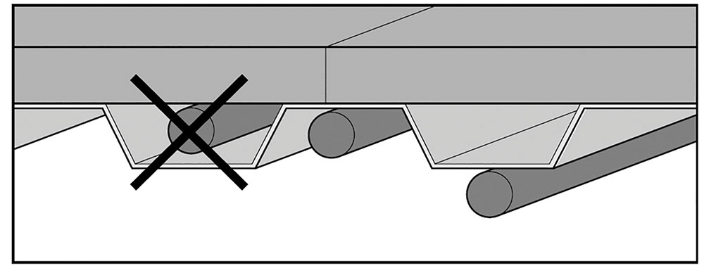
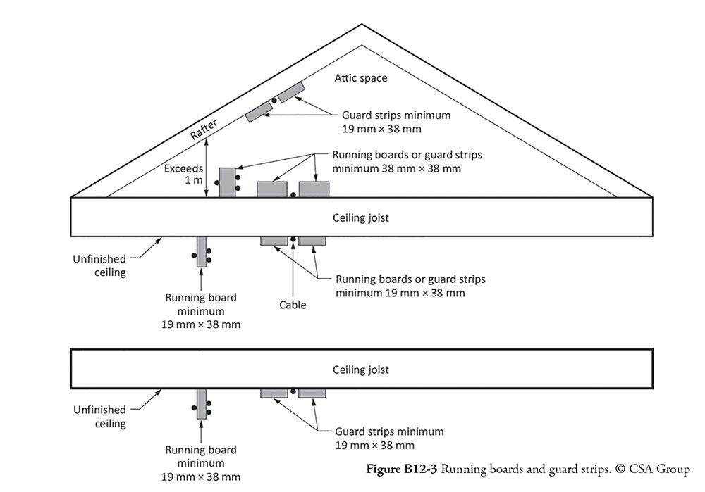
The running board and guard strip rules that were in Rule 12-214 were moved Rule 12-514. As part of this move, the rule was expanded to provide direction on the size of running boards and guard strips and where they should be installed. Guard strips consist of two boards, one on each side of the cable to be protected, and running boards are placed with the cable secured to the side of the running board. In an attic running boards and guard strips are required to measure not less than 38 mm by 38 mm and be installed to prevent damage from a person stepping or kneeling on the cable. To assist code users, Figure B12-3 was added to Appendix B to illustrate the proper use of running boards and guard strips.
Rule 12-516 Protection for cable in concealed installations has a newly inserted Subrule 2) that requires cables to be installed a minimum of 38 mm from the front edge of studs and joists that can be drywalled. Where the 38 mm clearance can not be met, corrosion-resistant ferrous metal of not less than 1.3 mm thick is mandated to be securely fastened in place, and that will extend beyond the face of the stud or joist in such a manner that it will cover the width of the cable or group of cables.
Rule 12-518 Protection for cable in exposed installations has also been expanded by added a new Subrule 2) allowing non-metallic conduit or tubing to be used as a sleeve for the mechanical protection of non-metallic-sheathed cables. The ends of the raceway will require a bushing or equivalent to prevent damage from abrasion, and the raceway fill will be limited to the percentages mandated in Table 8.
To be constant with non-metallic-sheathed cables rules, Subrule 1) of Rule 12-616 Concealed armoured cable installation has been expanded to similar protection plate and cylindrical bushing requirements. In addition, the cable support reference to Rule 12-510 in Rule 12-618 Running of cable between boxes, fittings, etc., was replaced with the same support spacing requirement of not more than 1.5 m throughout the run and allowance to fish cables. The maximum distance between the cable terminations and the first cable support has changed for armoured cable allowing up to 600 mm for cables with a connector trade size between 35 and 78 and up to 900 mm for cable with a connector trade size greater than 78.
Table 6, Table 9, and the reference Rule 12-910 Conductors and cables in conduit and tubing has significant changes that should make it much easier to establish the maximum number of insulated conductors that can be installed in a raceway. Other than HDPE conduits, the new Table 6 and Table 9 are accurate for all conduits and tubing types.
The number of Table 6 tables remains the same. The 2018 CE Code Table 6 tables provided the maximum number of conductors that could be installed in conduit or tubing. The 2021 tables provide the mm² area of single conductors and cables for calculating conduit and tubing fill.
Table 9 has been reduced from sixteen tables (pages) to eight tables with two tables each for the allowable fill percentages of 100%, 53%, 31%, and 40% for the various trade conduit and tubing.
Now, let’s look at an example installation of ten – #14 AWG RW90 unjacketed 600V insulted conductor in rigid metal conduit. To establish the conduit size, start with Table 6A that shows that the total cross-sectional area of the ten #14 conductors is 88.67 mm². Now go to Table 9G for a maximum of 40% fill. The 40% cross-sectional area of 16 trade size rigid metal conduit is 80.93 mm², not large enough for the ten # 14 AWG conductors (88.67 mm²). The 40% cross-sectional area of 21 trade size rigid metal conduit is 141.6 mm²; this is large enough for the ten # 14 AWG conductors.
Rule 12-2202, Insulated conductors and cables in cable trays, has significant changes. First is a new Subrule 1) that recognises the revised definition for cable tray as supporting means for cables. Subrule 3) has been expanded to limit the size of cables marked as TC-ER to not smaller than 1/0 AWG. Subrule 4) provides better clarification on the requirements for mechanical protection and no longer limits runs of cable marked TC-ER outside of a cable tray to 7.5 m. Subrule 5) has removed the reference to Table 19 and provides a list of the thermoset insulated conductors and cables not smaller than 1/0 that can be installed in cable tray in electrical equipment vaults and service rooms, and other locations that are inaccessible to the public and are constructed as a service room where a deviation has been allowed in accordance with Rule 2-030.
The final significant change in Section 12 is the Subrule 2) rewording of Rule 12-3034 Maximum number of insulated conductors in a box. In addition to making the subrule easier to read, a new example table has been added in Appendix B. The subrule now also mandates the largest size of the conductor be used in the conductor count when more than one size of conductor is used.
Section 14
Section 14 has two changes for the 2021 CE Code. First is and new Item f) for Rule 14-014 Series rated combinations that limits the motor contribution into a series rated combination. The maximum rated motor full load currents that can be connected between a series rated combination now can not exceed 1% of the interrupting rating of the lower-rated circuit breaker.
The second change in Section 14 was to change the items in Rule 14-100 Overcurrent protection of conductors to subrules and the insertion of a new Subrule 2) that recognizes that consumer’s service conductors considered protected by the service equipment overcurrent.
Section 16
Section 16 has two significant changes. The first change is a direct result of a question raised by an IAEI NEWS reader. It was common practice to install Class 2 transformers with 15A overcurrent protection in the primary circuit. The wording of the 2018 CE Code does not allow this practice. Prior to the rewrite of Section 16 in the 1978 CE Code, the 1975 edition of the CE Code allowed a 15 A overcurrent device in the primary circuit of a Class 2 transformer. The rule from the 1975 edition of the CE Code was deleted as part of a rewrite of Section 16 in the 1978 edition. A previous IAEI NEWS article on transformer overcurrent protection was raised by a question an IAEI NEWS reader regarding the maximum overcurrent protection allowed for a Class 2 transformer. As a result, a new Subrule 2) was added to Rule 16-202 Methods of installation on the supply side of overcurrent protection, transformers, or devices having Class 2 outputs. The new subrule allows a 20 A rated overcurrent device to protect the supply side of transformers or other devices having Class 2 outputs. The rating of 20 A aligns with the product standards for transformers or other devices having Class 2 outputs.
The final change for Section 16 is a revised Subrule 8) for Rule 16-330 Cables and conductor ampacity for Class 2 power and data communication circuits. The 60 W or less exemption to apply cable bundling rules has changed to the rating of each output circuit supplied by power sourcing equipment not to exceed 0.3 A. The minimum 24 AWG requirement has not changed.
The next article will continue with Section 18 Hazardous Locations changes.