Before we get into the details of conductors, currents, and circuit protection on the AC side of the PV system, let’s step back and try to get a bigger picture of where are some of the dangers or hazards that need to be considered.
Shock hazards. On the AC side of the PV system, many things are the same as they are on the DC side. Most electrical professionals know that AC voltages above 15 V and DC voltages above 30 V can pose shock hazards, and if the currents get above 10 to 25 mA, those shock hazards can become deadly. DC PV voltages can be as high as 1,500 V and even in residential PV systems, 600 V on the DC side is common. Even the off-grid, low-voltage battery systems with 24 V and 48 V batteries have voltages that can be lethal. Currents on the DC side can be hundreds, if not thousands, of amps depending on the size of the PV system. On systems with voltages more than 600 V—particularly on AC circuits at 5,000 V and above—engineers should be involved in the design and certified electricians should make the connections.
These voltages and currents are certainly hazardous. Previous articles have addressed the National Electrical Code (NEC) requirements and methods by which they can be controlled and how the circuits and equipment can be protected from faults. Of course, safety during the installation and inspection of these systems dictates that we avoid working on energized circuits if possible and always use proper Personal Protective Equipment (PPE).
Voltages and currents are typically more than the shock and lethal current value, and circuits and components must be appropriately rated. However, there is a new hazard of which we must be aware and deal with on the AC side. That is the concept of the available short-circuit current that could flow into the PV system under fault conditions.
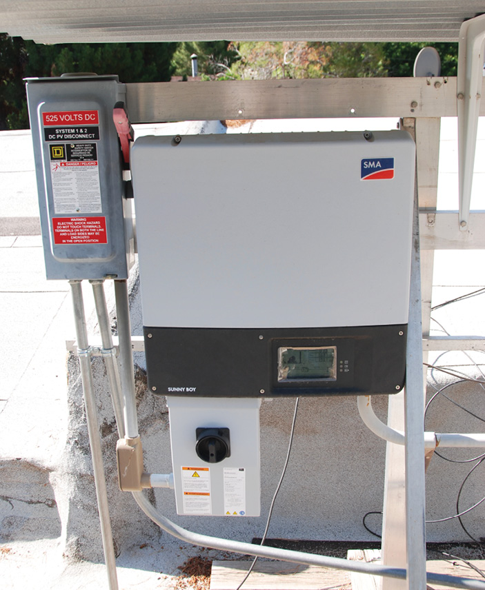
AC short-circuit currents. Most residential and commercial PV systems are connected to an existing AC electrical system which is connected to the utility grid. In general, the PV system has an output rating which is less than the rating of the service feeding the existing facility. Certainly, there are exceptions to this where a very large PV system is installed on a relatively-small AC service and the rating of the PV system might be equal to the rating of the service. On the large, utility scale systems where the utility interactive PV system is the only connection to the grid, then usually the rating of the PV system will be equal to the rating of the service. However, in most of these cases, the inverter AC output, no matter what size the inverter(s), will be current-limited. [See Photo 1.]
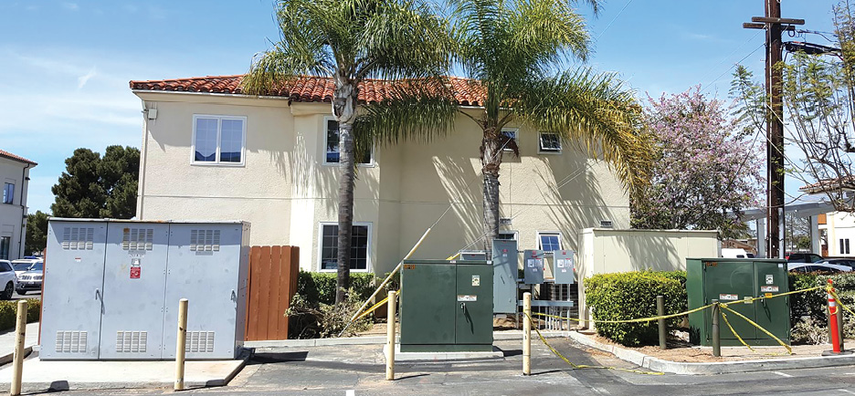
On the other hand, the utility grid—aside from overcurrent protection devices—is not limited in available fault current to levels associated with the rating of the PV system. For example, in a residential neighborhood distribution network, a single large transformer may supply several homes with overcurrent protection on only the primary side of the transformer. [See Photo 2.] The available fault current from the transformer at each service will be significantly larger than the output current rating of the PV system.
When overcurrent protection for the AC output circuits of the PV system from the output of the inverter to the point of connection to the existing utility is addressed, the available fault currents in the circuits will be much larger when sourced by the utility than when sourced by the utility interactive inverter.
Equipment in these AC circuits—including overcurrent protective devices, disconnect devices, and other devices that open the circuit or carry fault currents—must have a Short-Circuit Current Rating (SCCR) and/or an Interrupt Rating (IR). Under fault conditions, all properly applied devices that have appropriate SCCR and IR will be able to deal with the fault currents, be able to open the circuit without damage, and protect downstream connected circuits and components.
Conductors. In the PV system, conductors associated with the AC wiring are similar to AC conductors used throughout any commercial or residential electrical power system. Although they are not branch circuits, they are installed in a similar manner. The exception might be where the AC output of the inverter is connected by a supply-side connection to the service entrance. These supply-side connected conductors require more consideration in their construction and installation since they may be subjected to the full available fault currents from the utility service [705.12(A), 705.31]. Subsequent articles in this series will deal more specifically with supply-side and load-side connections.
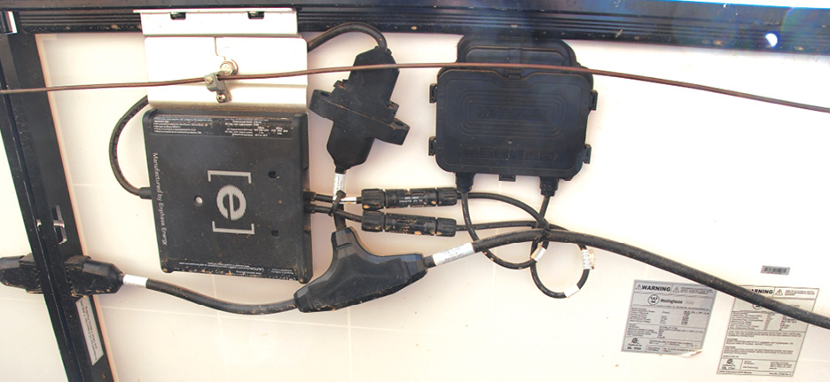
Other AC circuits that are slightly different would include the listed trunk cables used to connect the outputs of multiple microinverters or AC PV modules [see Photo 3] and the specialized listed cable assemblies and equipment used to combine the outputs of certain large string inverters without overcurrent protection or discrete disconnects for each inverter. [See Photos 4A, 4B & 4C.] There is no requirement in the Code for the AC output conductors from an inverter to be enclosed in metallic raceways as required for the DC conductors inside a building [690.31]. Of course, in commercial buildings there are frequently local codes and requirements that necessitate all circuits to be enclosed in metal raceways. There are restrictions on combining conductors of different circuits in the same raceway. For safety reasons, DC circuits from the PV array may not be enclosed in raceways with circuits from other non-PV systems, and this also includes the AC output circuit of the inverter [690.31(B)].Ampacity. The ampacity of conductors on the AC output of utility interactive inverters is based on the rated continuous current output of the inverter, known as the maximum current of this circuit [690.8(A)(3)]. The conductor ampacity is either 125 percent of the maximum current or the ampacity after conditions of use are applied [without the 125 percent factor], whichever is greater.
-
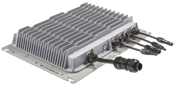
Photo 4A. Utility-interactive three-phase string inverter tested and listed for using connectors as disconnects for DC inputs and AC outputs. -
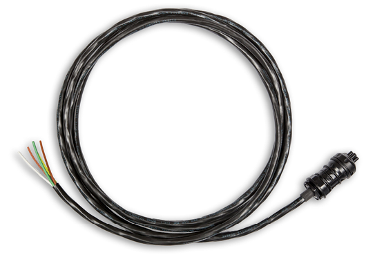
Photo 4B. Listed cable and connector listed as an AC disconnect. -
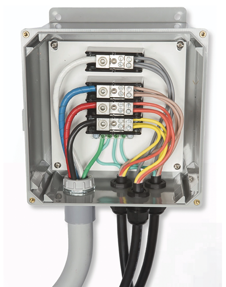
Photo 4C. Listed AC Combining Box that combines outputs of three inverters without overcurrent protection on each output. Courtesy Hi-Q Solar.
Overcurrent Protection. As noted earlier, AC circuits connected to the output of utility-interactive inverters are subjected to potential fault currents from both the inverter and the utility source. In line-to-line and ground faults, the inverter anti-islanding circuits will typically sense out-of-specification voltages and immediately shut down. However, in some cases of arcing faults, the inverter may continue to operate and supply fault currents.
In most fault scenarios, the utility will be the source of the highest available fault currents. When a given circuit is subjected to potential fault currents from two sources, the utility source is acknowledged to be the source of the fault currents that must be addressed with overcurrent protective devices [690.9(A)] This is specifically true in the case of utility interactive inverters which have current-limited outputs.
While there is no requirement to install an overcurrent protective device directly on the output of utility-interactive inverter, doing so may complicate or increase the conductor ampacity requirements of the conductors due to requirements in Section 705.12(B). In nearly all cases, the overcurrent protective device protecting the circuit conductor on the output of a utility interactive inverter will be at the utility end of the circuit. The rating of this overcurrent device will typically be 125 percent of the rated output current [maximum current] of the inverter.
The instruction manual for the inverter will have specific requirements for the maximum external overcurrent device that can be used on the AC output circuit. This restriction may be related to the requirement to protect conductors inside the inverter from overcurrent with an external device, but it should never be less than 125 percent of the rated continuous output current of the inverter after that number has been rounded up to the next standard overcurrent device rating.
Short-circuit & interrupt current ratings. Because of the high available fault currents [short-circuit currents] from the utility supply, circuits connected to the utility must receive additional consideration. Obviously, the conductors are sized for the normal continuous currents that they must handle. Typically, in a utility-interactive PV system, there are no noncontinuous currents. All circuits are rated based on the continuous-rated output current of the inverter which is appropriate since the inverters are current-limited.
The connected equipment between the utility point of connection and the inverter AC output must address fault currents originating from the utility. This is accomplished by the SCCR and the IR of the equipment. Any device that must interrupt high currents [high currents or fault currents], must have an IR or Interrupt Capacity (IC) in excess of those currents [110.9, 110.10]. Devices that interrupt currents include switches, fuses, circuit breakers, relays, contactors, and in some cases solid-state devices.
Available fault currents at equipment terminals in DC circuits are calculated using the resistance of the circuit conductors [Table 8, Chapter 9]. In AC circuits, the available fault currents are calculated using the circuit impedances [Table 9, Chapter 9]. These more complex calculations start with information and specifications from the utility concerning the distribution transformer.
Devices that do not interrupt the current or are used in a manner that does not involve activating an interrupt feature [such as a closed switch], must have a SCCR consistent with the available currents that the device must carry under fault conditions.
In one- and two-family dwelling electrical services and small commercial services, there is a general assumption that the available short-circuit currents from utilities are less than 10,000 A. Items like meter sockets, meters, main breakers, and branch-circuit breakers are all rated at this 10,000 A for SCCR [meter sockets and meters] and 10,000 A of IR fuses or IC circuit breakers. However, this assumption may be incorrect if the utility has upgraded the distribution system in the neighborhood and the new equipment can deliver more than 10,000 A of available current.
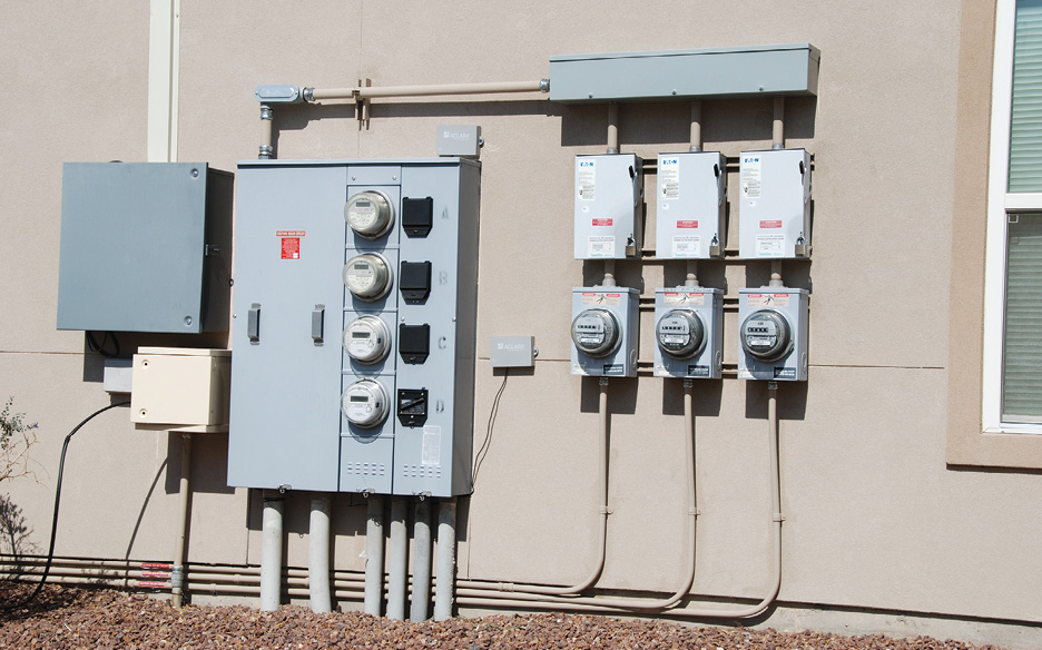
In making supply-side PV connections, it is always a good practice to verify the value of the utility-supplied fault current at the point of connection of the PV system. In some cases, the service-entrance equipment may have to be upgraded to higher SCCR and IR/IC ratings. Any supply-side connected PV equipment should have similar ratings. [See Photo 5.]
Carefully determine SCCR & IR. When installing unfused disconnects in AC circuits that could be subjected to high available fault currents, it is critical to determine the actual SCCR and/or IR of the disconnect. Unfused disconnects may have an IR as low as 5,000 to 10,000 A and require a series fuse with a 10,000 A interrupt rating, but they may be marked with a higher IR when protected by a series overcurrent device [normally a fuse] with a higher rating. [See Photo 6.]
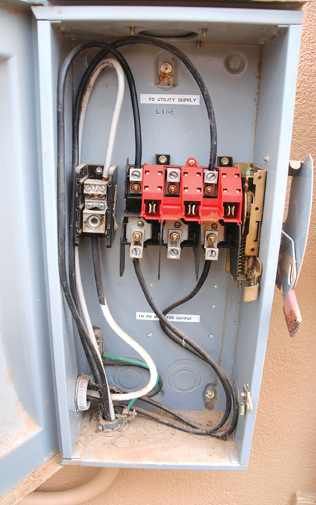
Sometimes, the labels can be confusing, and it is always a good idea to check the manufacturer’s full data sheet. Some manufacturers have unfused disconnects that can have a high IR when protected by a specific circuit breaker. Other unfused disconnects must be protected by a series connected fuse. The data sheets will be very specific in these varying requirements. [See Photo 6.]
Plan Reviewers may note the addition [or require the addition] of a transformer in the AC output circuits of the PV system to reduce the available fault currents from the utility to levels that can be accommodated by the installed PV equipment, disconnects, and overcurrent protection.
Voltage drop & rise. The NEC has Informational Notes with respect to voltage drops and suggests keeping them within 3 percent or 5 percent in a given circuit. These suggestions may not be adequate for a well-designed AC circuit from a utility-interactive inverter.
In a conventional [non-PV] electrical system, voltage drop is normally the decrease in voltage on a circuit starting at the utility source and ending at a particular point in the circuit, usually the load end of the circuit. The voltage at the meter socket, for example, is higher than the voltage at the receptacle outlet due to the fact that as the electrons flow through the resistance of the associated circuit conductors they create a voltage drop.
Voltage drop is kept under control by increasing the conductor size [reducing the resistance] where required over the minimum requirements for ampacity. There is sometimes a trade-off between increasing the conductor size and the inherent cost of increased copper versus the savings in energy lost in the smaller conductor. Although this is not a common trade-off in residential and small commercial installations.
In utility-interactive PV systems, the inverter becomes the source of current in the AC output circuit to the utility point of connection, and the utility resembles the load. The voltage on the AC output circuit of the inverter will be higher at the inverter terminals and will be lower than the voltage at the utility point of connection.
Assuming the utility voltage is the reference voltage for the system, the voltage will rise from the meter socket to the utility-interactive inverter terminals when the PV system is sending power to the utility. Even when the PV power is being absorbed by the local loads, the voltage at the inverter output terminals will be higher than the voltage at the end of the circuit connected to those loads and the utility.
Utilities typically maintain [or should maintain] the voltage at the service point of connection within +10 percent, -12% percent of the nominal voltage [240, 208, 480, etc.]. If the utility voltage happens to be at the upper end of the range, say +10 percent, and the voltage rise on the AC circuit to the inverter is 3 percent or 5 percent, then the voltage at the inverter terminals could be 13 percent to 15 percent above nominal. This, of course, could not occur with the current anti-islanding circuits in the inverter which limit the voltage on the inverter terminals to +10 percent, -12 percent. The inverter would shut down.
This situation is not uncommon. Some installers do not pay sufficient attention to the conductor sizes [other than basic ampacity requirements] for the inverter output circuits. Where the circuits are lengthy, the voltage rise may be 2 percent to 3 percent or more. In midafternoon, the utility connects voltage support capacitors to the distribution system to account for increasing air conditioner loads [which result in lowered line voltages] in the afternoon when people return home from work.
The resulting increase in line voltages may cause the voltage at the point of connection to the PV system to be close to +10 percent. This will result in the PV inverter shutting down until the utility voltages return to a lower value allowing the inverter to see terminal voltages no more than +10 percent above nominal. In this situation, the inverter will cycle on and off every five minutes until a satisfactory measurement of terminal voltage can be made.
For this reason, the voltage rise on the inverter AC output circuits should be restricted to as low a value as practical but usually 1/2 to 1 percent. This means that the conductor sizes on the circuit will be increased above the minimum ampacity requirements and the equipment grounding conductor will also have to be increased [250.122].
AC circuits in PV systems are sourced by current-limited utility-interactive inverters on one end and connected to the utility source on the other. Conductor size is based on the continuous output current rating of the inverter. Overcurrent protection is usually installed at the utility source end of the circuit because of the higher available fault currents from that source.
The IR and IC—which all devices use to interrupt currents in the circuit
—must be large enough to deal with all available currents that must be interrupted, including short circuit currents. Devices not interrupting currents in these circuits must have a SCCR sufficient to handle any potential normal or fault currents. Establishing the actual interrupt ratings of unfused disconnecting devices is important to ensure proper functioning under fault conditions.