Introduction
Ah, to be back in the 1970s and 1980s when photovoltaic (PV) systems were in their infancy, and the National Electrical Code (NEC) had not fully addressed all of the disconnect requirements for PV power systems in any detail. In fact, PV systems did not appear in the NEC until the 1984 edition of the Code even though those off-grid solar hippies in the more remote parts of the country had been using them since the mid-1970s. Disconnects (a.k.a. disconnecting means – a defined term located in NEC Article 100 entitled Definitions) are found throughout nearly all electrical systems, including PV power systems.
These disconnects provide a means to separate various portions of a circuit or equipment from other portions of the circuit or equipment in the same system. They also provide means of disconnecting one system from another system. As an example, the PV system disconnect allows the PV system to be disconnected from utility service or a battery system or other power source. The disconnects come in a wide variety of configurations, and some, although meeting the definition of a disconnect, may not resemble what most would consider a disconnect. Each edition of the NEC modifies, adds, and clarifies the various requirements for disconnects. In some cases, the disconnect requirements are very specific, and in other instances, they are more general in nature.
The Basics
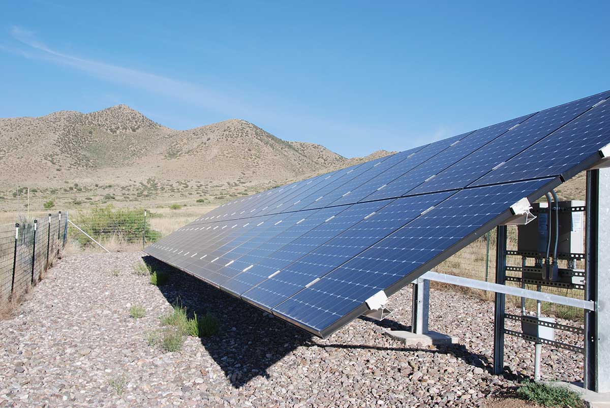
Types and Configurations. The most basic form of a disconnect may be a switch and that switch in dc circuits may have one or two poles, but generally, two-pole disconnects are used (see photo 1). When the switch is in ac circuits, it will typically have two or three poles (see photo 2) depending on whether the circuit is a single-phase or three-phase circuit. The switches shown in these photographs have an external operating handle (for operator safety), and exposed bladed contacts are visible once the cover of the switch enclosure is opened. These types of switches are commonly known as safety switches. Other types of switches may have the switching mechanism totally enclosed (except for the terminals) like the ubiquitous ac light switch used in dwellings and commercial buildings.

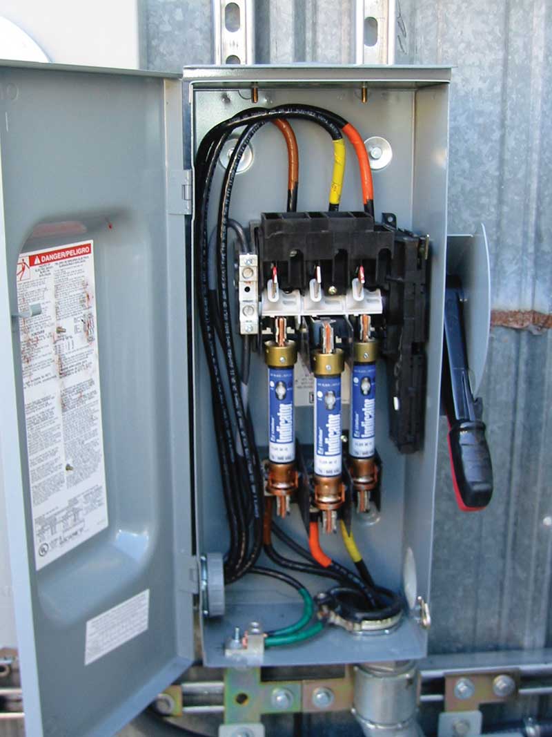
Photo 1. Unfused dc PV disconnect (aka safety switch). Two outer poles of the three-pole switch are being used. Note safety shield/barrier over upper terminals. The pass-through wires are probably grounded and should be marked white on this 2014 installation. Courtesy of John Wiles
AC vs. DC. It is important to ensure that the disconnect that will be used to interrupt circuits under load be properly rated for dc or ac or both for the currents in that circuit. AC rated disconnects must not be used on dc circuits, and that would be a violation of the listing [110.3(B)] as well as causing other problems.
Circuit breakers, both ac and dc, combine a switching action with an overcurrent device that simplifies system design and installation where both functions are required in a circuit at the same location (see photo 3). Circuit breakers come in single-pole, double-pole, triple-pole, and higher configurations.
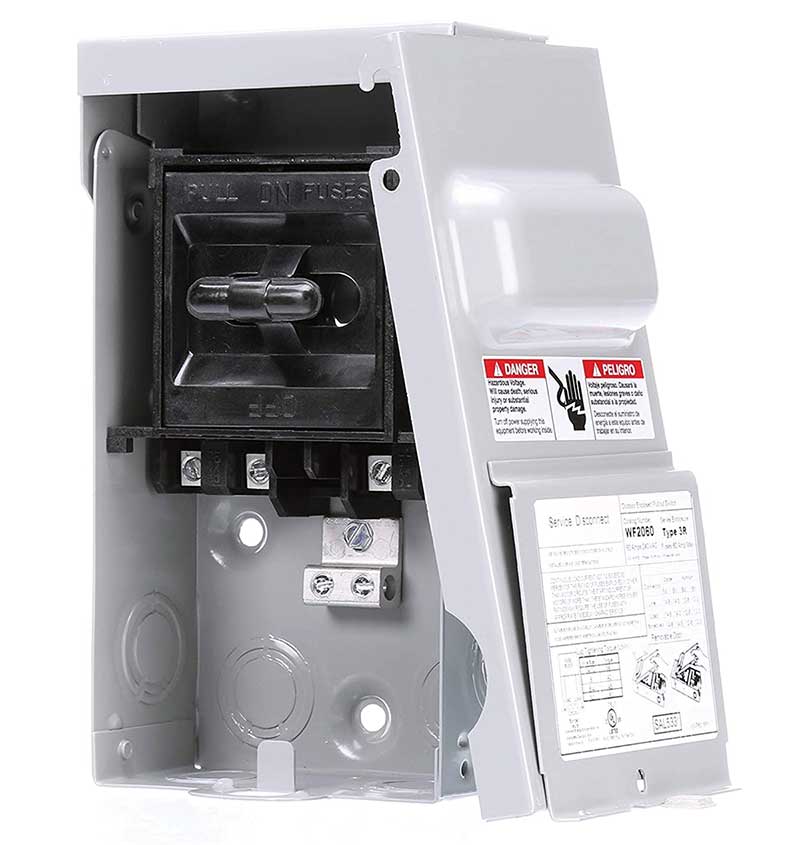
Some disconnects, primarily used in air-conditioning applications, are simple devices with pullout handles which perform the disconnect function. They may be either fused (providing integral overcurrent protection) or unfused (see photo 4).
Although not readily recognized as a disconnect, a simple connector also meets the definition. These connectors are used in a single-pole (single conductor) configuration on the output of PV modules (see photo 5).
However, they may have two or more poles when used as the disconnecting device on the trunk cable output of AC PV modules or microinverters. These connector disconnects may have limitations on their operation that will be discussed in the “Looking Deeper” section of this article.
![Photo 5. Single conductor connectors used as disconnects on PV source circuits. The connector in the rear appears to be mismatched between manufacturers and may be a Code violation [110.3(B)]. Courtesy of John Wiles](https://iaeimagazine.org/wp-content/uploads/2021/02/2020_09_WilesPH5.jpg)
Requirements. The NEC requirements for disconnects in PV systems are generally found in Articles 690, Solar Photovoltaic (PV) Systems, and Article 705, Interconnected Electric Power Production Sources. As the overall PV system is expanded to include energy storage systems (batteries), Articles 706 entitled Energy Storage Systems and Article 480 entitled Storage Batteries may be involved. Backup generators may add additional disconnect requirements. Where the PV system is connected to the utility service, Article 230, Services may establish more requirements for disconnects.
PV System Disconnect. Looking at the overall big picture of a utility-interactive PV system, it will be noted that there is a requirement for a PV system disconnect which allows the separation of the PV system from any other source of power, energy storage system (batteries) or utilization equipment (690.13). Informational Note Figure 690.1(b) shows the location of the PV system disconnect in various types of PV systems. It should be noted that in some systems, this PV system disconnect is in an ac circuit, and in other systems, it is in a dc circuit. This complexity increased from previous editions of the Code with the 2017 NEC.
The PV system disconnect must be installed in a readily accessible location [690.13(A)]. This definition can be found in Article 100 of the NEC. Note that roofs are not considered a readily accessible location. When the disconnect is accessible to unqualified persons and operates above 30 volts, the disconnect enclosure must have a lock or require a tool to open.
The PV system disconnect must clearly indicate whether it is open (off) or closed (on). If both the load and line terminals are energized in the open position, the disconnect must have the following warning [690.13(B)].
WARNING
ELECTRIC SHOCK HAZARD
TERMINALS ON THE LINE AND LOAD SID
ES
MAY BE ENERGIZED IN THE OPEN POSITION
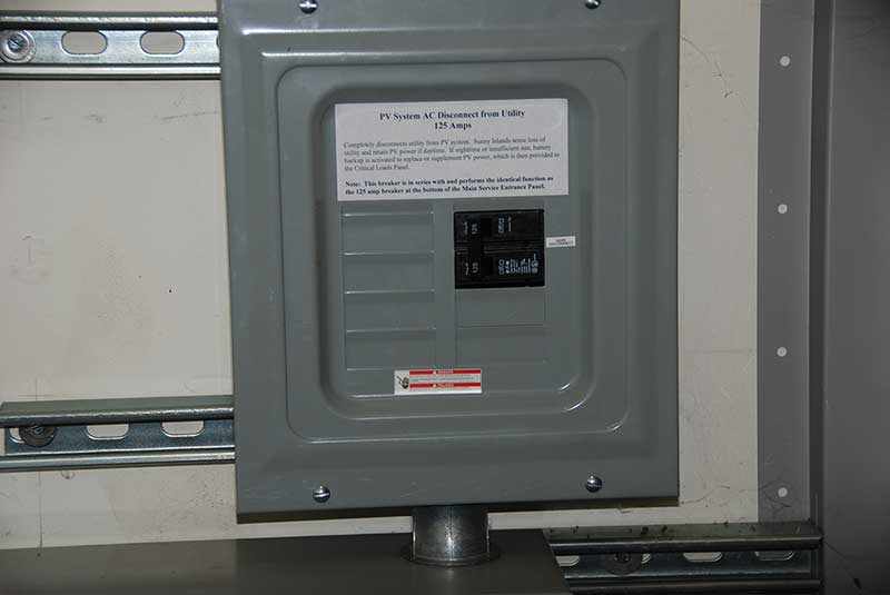
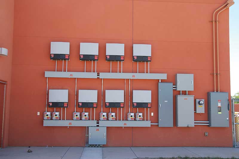
The number of disconnects for each single PV system is limited to six [690.13(C)]. However, this applies to each PV system on a building, and what actually constitutes a PV system is not specifically defined in the NEC. Therefore, possibly four, for example, PV systems could be installed on a building, and each could have up to six disconnects. Normally, this is not done, and the output of the various utility-interactive PV systems would be combined and run through a single disconnect for all PV systems (see photo 6).
PV Equipment Disconnects and Isolators. To facilitate safe maintenance of AC PV modules, fuses, dc-to-dc converters, inverters, and charge controllers, all conductors that are not solidly grounded are required to have disconnects. The disconnects must be within 3 m (10 ft) of the equipment and where readily accessible to unqualified persons and operating above 30 V, any door or cover on the enclosure must be locked or require a tool to open (690.15).
Isolating devices can be used to meet this requirement, but they are generally used and operated on circuits that can be de-energized from all sources of power before the isolating device is opened. Most of these devices must be marked “Do Not Open under Load” [690.15(B)], and this generally applies to connectors being used as equipment isolators on PV modules, dc-to-dc converters and the like. “Finger safe” pull out fuse holders serve as fuse isolators.
However, there are some applications where the dc connectors may be listed with the attached microinverter as being suitable for load break operation because the voltage and current are within the capabilities of load break operation. All PV module connectors are marked “Do Not Open Under Load” because at 600, 1000, or 1500 volts and at their rated short-circuit current, they would be damaged if opened under load. However, when connected to a microinverter, they are operated at far lower voltages (40-70) and may be suitable for load break operation. The microinverter or AC PV module manual will provide this information.
An equipment disconnecting means is a more robust device than an equipment isolator and is used to meet this requirement. It will be required to have the capabilities of opening the circuit under load and being able to interrupt the available current and voltage at its terminals. These devices are normally switches or circuit breakers, must be within 3 m (10 feet) of the equipment, and must simultaneously open all circuit conductors that are not solidly grounded [690.15(C)].
AC Disconnects. AC disconnects usually operating at 120, 240, 480 V or higher in a PV system are usually safety switches or circuit breakers because of the higher voltages and currents involved. For the most part, common ac disconnect installation practices would apply to the ac circuits in a PV system since those circuits are involved with circuits between the ac output of utility-interactive inverters and the utility.
Looking Deeper
Safety Switches. Safety switches evolved with that name because the marked LINE (upper) terminals are shielded (insulating barrier) and require a tool to access these terminals, thereby providing a safer connection point when the enclosure door is open. They also have exterior handles providing additional operator safety. The switchblades and any fuse holder contacts are exposed when the enclosure door is open, but they are connected to the marked LOAD (lower) terminals and are normally not energized when the disconnect is open provided there is no source of voltage or current connected to the load side terminals. This construction dictates that the most dangerous source (one that is always or frequently energized) be connected to the upper, “line” terminals. The shielding or barrier on these terminals prevents inadvertent contact with these frequently energized terminals when the disconnect door is open.
AC vs. DC. The currents in an ac circuit are sinusoidal in nature and, in the US, go through zero 120 times per second while reversing direction on the 60 Hz power system. The current flows first in one direction and then reverses and flows in the other direction through the conductor and the disconnect contact. During the opening of the disconnect contacts under load (current flow), an arc is formed. Arcs generate significant amounts of heat in the arc plasma that is formed and can damage contacts and even destroy disconnects if not properly addressed by the disconnect design. Remember arc welding? However, when the current goes to zero twice each cycle of the current sinewave, the arc is essentially extinguished and reignites when the voltage increases back towards the peak. Although we cannot see it, the arc is flickering on and off, and this results in a lower arc plasma temperature that reduces wear and tear on the contacts.
On dc circuits, the currents, on the other hand, are continuous in one direction and do not go through zero periodically. Therefore, the arc plasma temperature is substantially higher, and special designs are involved in dc rated disconnects (and fuses) to address those higher temperatures. Usually, the switching operation is much more abrupt on a dc-rated disconnect than on an ac-rated disconnect. It is difficult to extinguish these arcs in direct currents, and special designs must be used for the contacts and also in dc rated fuses. Those of you who are welders will recall that dc arc welding is substantially hotter than ac arc welding.
AC Circuits. For ac disconnects, the utility source should be connected to the upper “line” terminals of the disconnect. This is normal practice in most electrical systems since the power flows from the utility source to the load utilization equipment. In the utility-interactive system, the utility-interactive inverter will be connected to the lower “load” terminals. And, as required by various standards, when the disconnect is opened removing utility power from the output terminals of the utility-interactive inverter, that inverter must cease exporting power and drop its output voltage very rapidly (less than 2 seconds) to zero. Therefore, it is generally safe to open an ac disconnect, open the door of the disconnect enclosure, and find that while the upper “line” terminals may still be energized by the utility, the lower “load” terminals and any associated fuse contacts are now de-energized.
However, it is extremely important in all situations that any exposed electrical circuit terminals be measured for voltage line-to-line and line-to-ground to ensure that there are no voltages present before touching those terminals. Electrical and electronic equipment can fail and have been known to deliver dangerous voltages to those “load” (lower) terminals.
DC PV Circuits.In the daytime (including before sunrise and after sunset), the PV modules, PV strings, and the PV array can generate hazardous voltages and currents. For this reason, the PV dc output circuits should be connected to the “line” (upper) terminals of the safety switch. The inverter input terminals will then be connected to the “load” (lower) terminals. However, most utility-interactive inverters have large energy storage or filter capacitors in their input circuits, and even after the PV source has been removed from those inverter input terminals, the circuits and the “load” (lower) terminals may be energized for up to five minutes.
Where PV rapid shut down circuits are required, the inverter may be marked as PV Rapid Shutdown Equipment (PVRSE). The terminals on the inverter input are required to drop to less than 30 volts within 30 seconds once the PV source voltage has been removed upon activation of the PV rapid shutdown system.
Because potentially dangerous voltages may be on the “load” (lower) terminals, a warning is required on this dc PV disconnect.
WARNING
ELECTRIC SHOCK HAZARD
TERMINALS ON THE LINE AND LOAD SIDES
MAY BE ENERGIZED IN THE OPEN POSITION
And, as above, it is important to measure the voltage present with the proper testing equipment on any terminals that are going to be touched with bare hands. Also remember to evaluate and use proper personal protective equipment when working around energized electrical equipment.
Type of PV System Disconnect.Section 690.13(E) shows five types of disconnects that may be used for the PV system disconnect. They range from a simple connector meeting certain requirements to a remote-controlled switch or circuit breaker that is operated locally and opens automatically when control power is interrupted. Other options listed include a pullout switch, a manually operated switch or circuit breaker plus a device listed or approved for the intended application.
Location, Location, Location. As noted above, the PV system disconnect can be located on the ac output circuit of a utility-interactive PV inverter, but the location has to be planned to avoid unnecessary additional disconnects. If the inverter is close to [within 3m (10ft)] and within sight of the main building load center and a backfed breaker in that load center is used as the PV system disconnect, then only a single disconnect is required. If the local utility requires an outside disconnect, then an additional disconnect may be required. The requirement for an equipment disconnecting means on the ac side of the inverter is met by this single backfed circuit breaker. Locating the PV inverter out of sight of the building load center or point of connection to the utility service will generally require an ac disconnect near the inverter as well as the backfed breaker in the service panel or a separate ac disconnect for a supply side utility connection, if used.
On the dc input to the utility-interactive inverter, a dc disconnect must be present on the incoming dc circuits from the PV array. This disconnect must be located within 3 m (10 feet) of the inverter and within sight of the inverter. In some cases, an internal dc disconnect in the inverter may be acceptable to the local authority having jurisdiction (AHJ). The presence of a PV rapid shut down system which brings the dc PV output conductors to a low voltage within 30 seconds has alleviated the earlier Code requirement to have a PV dc disconnect on the dc conductors from the PV array at the point of entry to the building. The presence of this rapid shutdown system may also facilitate the approval for the use of an internal dc disconnect in the inverter.
Emergency Disconnects. New to the 2020 NEC are the requirements for emergency power source disconnects located on the outside of the single-and two-family dwelling. These emergency disconnects are required for the utility service [230.85], energy storage systems [706.15(A)], and storage batteries [480.7(B)]. It seems logical that these emergency power source disconnects be co-located with the required PV rapid shutdown initiator (690.12), and proposals have been submitted through IAEI to NFPA for consideration towards the 2023 NEC. Also, public inputs to NFPA have been submitted to extend the emergency disconnect requirements to stand-alone PV systems, fuel cells, wind and hydropower systems. While remote-controlled disconnects will be allowed, the disconnects must automatically open upon loss of control signal or control power.
LINE AND LOAD Markings. An Informational Note after Section 690.15(E)(5) states that circuit breakers marked “line” and “load” may not be suitable for backfeed or reverse current. This is particularly true on dc circuits, and most dc-rated circuit breakers have neither the “line” nor “load” markings.
Section 705.12(D) indicates that fused disconnects are suitable for back feed unless otherwise marked. This would also apply to unfused disconnects in most cases. The presence of “line” or “load” markings on a fused or unfused disconnect is primarily used to indicate that the utility should be connected to the “line” terminals, and these markings should not be used as an indication concerning back feeding. Unlike circuit breakers, any prohibition against back feeding will be plainly marked on the specification label provided on the disconnecting means.
Summary
There are currently numerous requirements in the NEC for disconnects in PV systems, and they increase the safety, operability, and maintainability of the equipment and the systems. Some attention must be directed to the proper application of the correctly rated disconnect in each location. The requirements for disconnects in ac circuits differ from the requirements in dc circuits. And the end for disconnect requirements does not appear to be in sight.
Electronics has come to overcurrent devices and will also come to disconnect devices. More and more of the required disconnects will be remotely operated, and these allowances and requirements will be addressed in future editions of the NEC.