
Introduction
The times they are a changing—and rapidly too. Coronavirus/COVID-19 has deeply affected the world we live in. Ways of doing business, interacting with each other, and even conducting electrical installations and electrical inspections have changed, are changing, and will continue to change. Not only has this pandemic affected society, global warming with predicted increasing numbers of hurricanes and other significant weather events will also affect “business as usual.” The 2020 National Electrical Code (NEC) has significant changes that address the evolving technologies in electrical power systems. The 2023 Code is expected to continue with more detailed requirements as these technologies become commonplace in the electrical power and now communications/computer industries and in the homes and buildings that require inspections.
The Basics
This article will present an overview of some of the new systems that have evolving requirements in the NEC. They will include energy management systems (EMS), microgrid interface devices (MID), power control systems (PCS), DC microgrids (DCM), and energy storage systems (ESS).
Energy management systems (EMS) [Article 750] have been around for a number of years. They have normally been found in commercial and industrial electrical installations. As we move into times of increasing electrical rates and more intense use of electrical devices and appliances, energy management systems have become more commonplace. The reason is relatively simple. Not all of these electrical devices need to be operating and drawing full power/energy at the same time, and many are not used at all during hours where the business or factory is not active.
For larger customers, the utility companies establish demand charges where excess consumption of electricity over some nominal/average hourly or daily rate is subjected to substantially increased charges per kilowatt-hour. In many cases, the demand charges in a given month may exceed the charges for the base energy usage for that month. It becomes cost-effective for the electrical customer to install an energy management system that monitors many, if not all, of the various loads throughout the building and controls the use of those loads (where operationally possible) so that the maximum baseload kilowatts/kilowatt-hours are not exceeded (or at least minimized) at any particular time of day.
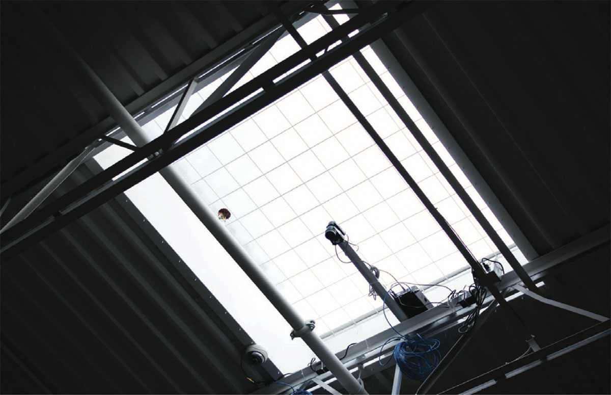
This may be as simple as cycling on and off large air-conditioners or refrigeration compressors at a rate that will not significantly affect the cooling of the building or the refrigerator/freezer but will reduce the average kilowatt-hour load of these devices. Another option, becoming common in large supermarkets and other big box stores, is to install skylights throughout the roof/ceiling of the building. The incoming sunlight from the skylights is monitored, and the interior lighting is automatically controlled to reduce lighting loads. In many areas, the light from sunlight through the skylights is sufficient to allow the interior space electrical lighting systems to be turned completely off. The system is quite responsive, and it will take a sharp eye to catch the transition between daylighting, and florescent/LED lighting when clouds pass over the store [see photo 1].
And with the evolution of the Internet Of Things (IoT) we have smart, Wi-Fi-connected thermostats, door openers, refrigerators, ranges, and other home appliances being operated remotely or being controlled by software that can reduce the energy usage of these devices. Where the utility provides a time-of-use rate structure, energy management systems may automatically delay the operation of some appliances to times of the day (i.e., at night) when electrical energy rates are the lowest. These energy management systems may also schedule building loads when peak solar energy is available in mid-day.
With five sections, Article 750 is relatively small and will be covered in more detail below. As is common with these systems, the AHJ should become familiar with the installation manual and operating modes of these systems to perform a full and detailed inspection to ensure that the system has been installed and adjusted in full compliance with the requirements of the Code and the instruction manual [110.3(B)].
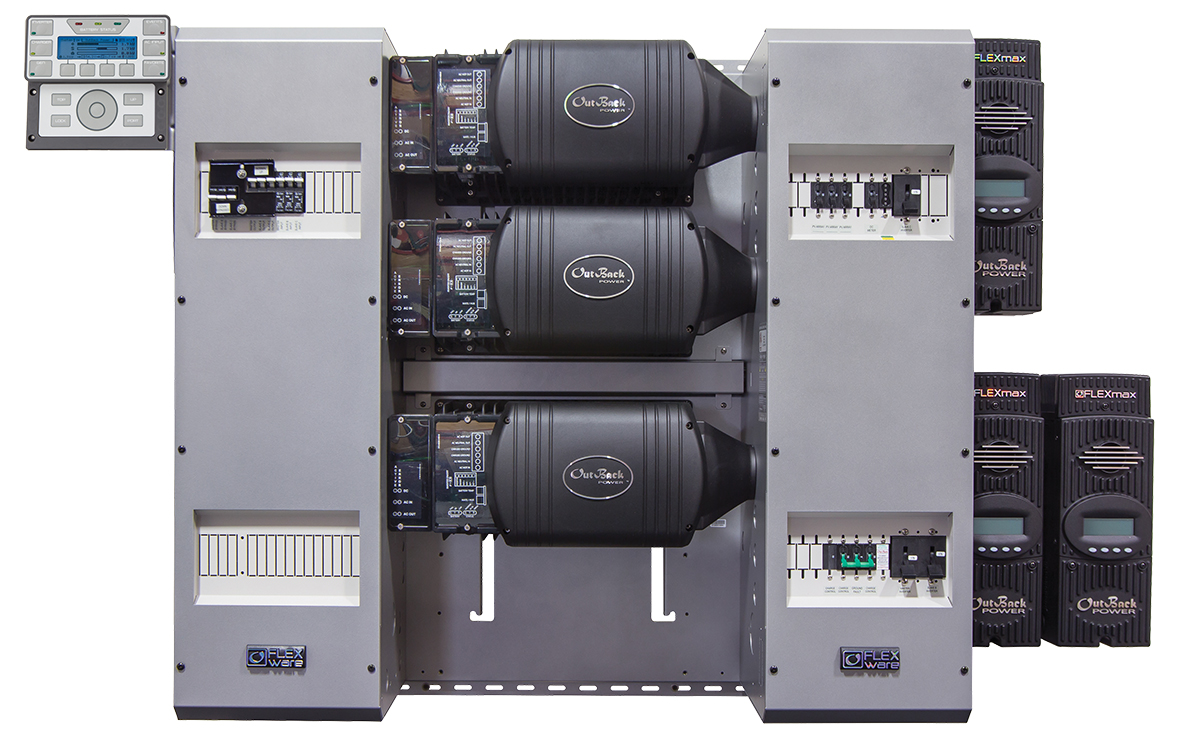
Microgrid interface devices (MID) [705.70] are used to connect microgrids (Part II of Article 705) to a primary power source. Microgrid interface devices are going to become more common as various types of microgrids are designed, developed, and installed to deal with fluctuating electrical utility supplies. For example, numerous dwelling units and larger commercial buildings are being equipped with microgrids to deal with utility outages during forest fire season in the Western states. These devices must be listed or field labeled and may frequently be internal to a multimode utility-interactive inverter or energy storage system (see photo 2). When internal to these systems, the MID will not appear as a separate device, but the functions will be included in the overall listing of the product or system in which they are installed. They may include overcurrent protection for power flowing both into and out of the microgrid, and they may provide synchronization functions.
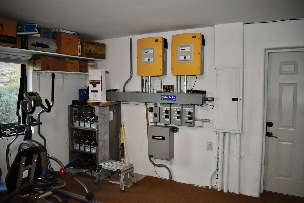
Power control systems (PCS) [705.13] are currently being installed as part of battery backed up PV systems, which include the PV power source, a battery or energy storage system, and a connection to the utility grid. In a similar fashion to the microgrid interface device, the power control system may be integrated fully into a listed energy storage system or into a multimode utility-interactive PV inverter or maybe a standalone device (photo 3). The power control system may control the output of multiple power sources and may also interact with an energy management system to control loads.
The main intent of the PCS is to allow energy sources and, in some cases, loads to have individual ratings and output circuit overcurrent protection that, when summed, exceeds the rating of any busbar or conductor to which they are connected. Section 705.12(B) does not have provisions for these types of connections. However, the power control system will monitor the total current going into and possibly out of a busbar or conductor and control the various sources and/or loads on that busbar or conductor so that the rating of the busbar or conductor is not exceeded. This is a new concept in the Code, which relies on the correct installation and adjustments of the power control system to ensure that there are no safety issues. The systems are of such complexity that the NEC cannot specifically provide installation or operation instructions to deal with each individual system. Therefore, the authority having jurisdiction (AHJ) is going to have to become familiar with the installation instruction manuals for these devices. They will need to verify in some detail, the actual installation and adjustment of the equipment associated with these devices as well as the correct operation of these devices. These devices are relatively new, and the installers of these devices may be no more familiar with the installation, proper adjustment, and operation of these devices than the AHJ.
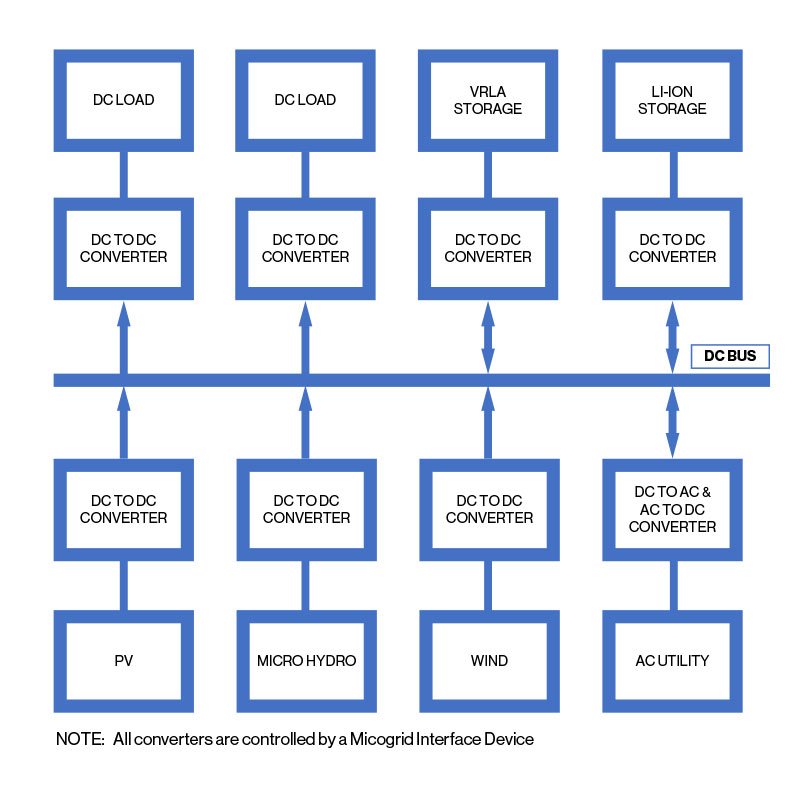
Direct-current microgrid systems (DCM) [Article 712] are currently being used in some commercial and industrial applications and will receive considerably wider installations at dwelling units as time progresses. Increasing requirements to meet energy efficiency demands by consumers and other users of commercial electric power will drive the installation of these DC microgrid systems. Most of the electrical appliances, with the exception of high-powered electric ranges and dryers, operate internally on low voltage direct current. Even high-efficiency air conditioners using electronically commutated motors have the electronic sections operating on direct current. The conversion of 120 V or 240 V AC to lower voltage DC is inefficient, and considerations are being given to operating these appliances on a DC microgrid without the conversion from AC for each appliance. The DC microgrid might be powered by a photovoltaic power system, a wind power system, or even connected with appropriate conversion devices (bidirectional or unidirectional) to the utility grid (see photo 4).
While Article 712 deals with many of the normal wiring methods, disconnecting means, and overcurrent protection requirements for the DC microgrid, Section 210.5(C)(2) covers the requirements for DC branch circuits. Organizations are currently writing standards and codes for the various nominal DC voltages and interface requirements for residential and commercial use of appliances on DC microgrids. It is fully expected in the not-too-distant future that we will have both AC and DC branch circuits in most new dwellings and commercial buildings.
Energy storage systems (ESS) [Article 706] are and will become commonplace in not only dwellings but commercial buildings and utility power generation systems employing renewable energy. In addition to providing energy during utility outages, these energy storage systems (batteries and other electrical or mechanical systems) can level the energy output of renewable energy systems, which vary with the available sunlight or wind. Utilities are very interested in battery type ESS as well as pumped water storage to deal with fluctuating loads and energy sources (see photo 5).

Looking Deeper
As we examine the NEC requirements for each of these new devices or systems, we must keep in mind that the Code will only have very basic requirements for a generalized version of each system. Some of these devices or systems may be completely self-contained such as the microgrid interface device (MID) functions that are totally enclosed and included in a multimode inverter such as utility-interactive functions and battery backup functions. On the other hand, an energy management system (EMS) for a large commercial building may have sensors and subsystems scattered throughout the building, which are linked to a central control system. The bottom line is, the person inspecting the systems will have to become intimately familiar with the requirements found in the instruction and operation manuals for these systems. Plan reviews before the on-site inspection will become increasingly important.
EMS (Article 750). The Informational Note on Section 750.1 indicates that other codes may affect or restrict the requirements contained in this NEC article. Those may include building codes and energy conservation codes.
In Section 750.2, the definition of an EMS includes the monitoring and/or controlling of a power production or storage source. To some extent, this will overlap the functions of a power control system (PCS), and, at some point, it should be expected that both of these systems may be installed on the same building. This possible event may occur because the systems may have been installed at different times.
Section 705.20 indicates that there are a number of critically sensitive and essential loads and that the EMS may not interfere or override any controls necessary to ensure continuity of an alternate power source for these critical loads.
Section 705.30 continues the restrictions on the EMS as it relates to load shedding and disconnection of power, again, related to critical systems. Also, this section requires that the operation of an EMS not result in the overloading of any circuit or the service.
MID (705.70). As defined in 705.2, a microgrid interface device enables a microgrid system to separate from and reconnect to operate in parallel with the primary power source. The Informational Note on 705.2 provides substantial numbers of references, mostly IEEE standards, that provide additional information on how these devices are designed and operate.
In Article 705, Part II, the microgrid interface device requirements are contained in Section 705.70, which is very short. The microgrid interface device is required for any connection between a microgrid system and a primary power source. It must be evaluated for the application, be field labeled, or be listed for the application. And it must have sufficient numbers of overcurrent devices located to provide overcurrent protection from all sources.
PCS (705.13). Power control systems must be listed and evaluated to control the output of one or more power production sources, energy storage systems, or other equipment. The PCS must limit the current and loading on busbars and conductors supplied by the PCS.
When a power control system is involved, any circuits on the load side of the service disconnecting means must meet the requirements of 705.12(B) or have all conductors and bus bars monitored so that none of the monitored busbars or conductors can be overloaded from any or all sources
When the PCS is connected on the supply side of the service disconnect, the service conductors must be monitored to ensure that they are not overloaded.
Section 705.13 (B) provides some very basic information about settings in the PCS, and 705.13(E) requires that only qualified personnel have access to these adjustments or settings. The sum of all currents controlled by the PCS plus the currents monitored by the PCS may not exceed the rating of any busbar or the ampacity of any conductor supplied by the power production sources or ESS. This is where things may get a little confusing.
The overcurrent protective devices may have ratings that, when summed, exceed the rating of the busbar or conductor to which they are attached. In a similar vein, power production sources may have rated outputs that, when summed, exceed the rating of the busbar or the ampacity of the conductor that they feed. The purpose of the power control system is to restrict the sum of the outputs of the various power production sources or energy storage systems so that they do not exceed the rating or ampacity of the circuits to which they are connected. The PCS will electronically control the output of the various sources to achieve this objective.
Section 705.13 (D) requires that the rating of the overcurrent protective device for any single power source controlled by the PCS shall not exceed the rating of the busbar or the capacity of the conductor to which it is connected. This requirement does provide some basic circuit protection for single sources from potential overlords. It does not, however, affect situations where there are multiple sources, and the power control system fails in its required actions.
DCM (Article 712). This article, which has seven parts and numerous sections, appears to pull together existing DC circuit requirements from other articles and also overlays the normally expected requirements that would appear in AC circuits.
The DC microgrid may include multiple DC sources such as AC to DC converters, PV systems, wind generators, energy storage systems, and fuel cells. Normally, the DC microgrid is not directly connected to an AC primary source of electricity, but it is anticipated that many installations will have DC – AC bidirectional converters or inverters.
As in PV systems, there will be ungrounded DC systems; reference grounded DC systems, functionally grounded DC systems, and three-wire and two-wire reference grounded systems. DC equipment used in the DC microgrid shall be listed and labeled for DC use. See 712.2.
Directories are required for all DC sources as well as a building directory (712.10).
Part III covers disconnecting means, which include readily accessible disconnecting means that are lockable for each DC source and, in general, will open only the ungrounded conductors. Resistively grounded systems and reference grounded systems shall have all current-carrying conductors opened by the disconnect.
Part IV includes system grounding. Section 250.162 gives the general guidance on grounding, and it is further modified by sections 712.52 and 712.55 and 712.57. DC microgrids operating over 300 V shall be reference grounded or functionally grounded. DC microgrid systems other than those that are solidly grounded that operate over 60 volts shall have a ground fault detection system that indicates that a fault has occurred.
Arc fault protection shall be required for DC microgrid circuits where such protection is required by other parts of the code. In some cases, appropriate equipment will not be available, and the allowances of NEC 90.4 should be used.
The available DC fault current for each of the DC sources shall be marked at each source, and the evaluation/calculation date. When modifications are made to the DC microgrid that may affect available DC fault currents from any source, those fault currents shall be recalculated and marked and dated at each source.
Equipment and conductors in the DC microgrid system shall be protected from overcurrents from all sources. The interrupting rating and short-circuit current ratings of each overcurrent protection device shall be sufficient to deal with the fault currents at the line terminals of the equipment.
ESS (Article 706). This extensive article provides somewhat detailed requirements for energy storage systems. A change for the 2020 NEC has reduced the number of systems that have been defined and essentially requires that the entire ESS system be listed (706.2, 706.5). This requirement may pose issues in many installations. The delineations between an energy storage system, a battery system, and possibly a standalone or multi-mode PV system have not been clearly made. They may have to be clarified in future editions of the Code. Each energy storage system is different and will require significant amounts of attention to the installation and operating instructions of each. Although Article 706 contains abundant requirements, it does not address how to specifically install, adjust, or operate any particular energy storage system. The complex requirements of Article 706 will be addressed with an extensive review in a future article in this series.
Summary
We are rapidly moving into a world of software-driven, computer-controlled electrical power systems. The installation, adjustments, and operation of these electrical power systems may no longer rely on simple calculations of conductor size, busbar ratings, and overcurrent protection. In order to maximize system efficiency and provide maximum operational flexibility while minimizing costs, installations of systems described above, and even more complex systems will become commonplace. With the Internet of Things (IoT), many electrical devices that are now manually operated will have those operations and power draw controlled by software in “black box” devices. Smart homes and smart PV inverters are just coming to the market. Stand by; the fun is just starting. Please read those installation and operation manuals.