The recent IAEI News reader survey has shown, as expected, that many of the readers are experienced, well-informed electricians, PV installers, and electrical inspectors who have been dealing with photovoltaic (PV) systems for many years. However, the survey also indicated that there are more than a few readers who are electricians not familiar with PV systems interested in getting into the business. There are also significant numbers of electrical inspectors that are new to the field of inspecting PV systems. For this reason, future articles in this series will have two sections. The Basics section will start the article by providing information that would be of use to individuals new to PV systems. The Looking Deeper section will provide a more detailed explanation of the subject for the more experienced readers.
Subsequent articles will be based on the 2020 National Electrical Code (NEC) with a few references to the 2017 NEC, where there are significant differences. For those individuals in jurisdictions using the 2017 NEC or earlier additions of the Code, you may find my detailed articles on the numerous NEC requirements for PV systems in the archives of these articles on the IAEI Magazine web site (https://iaeimagazine.org/author/jwiles/).
PV System BASICS
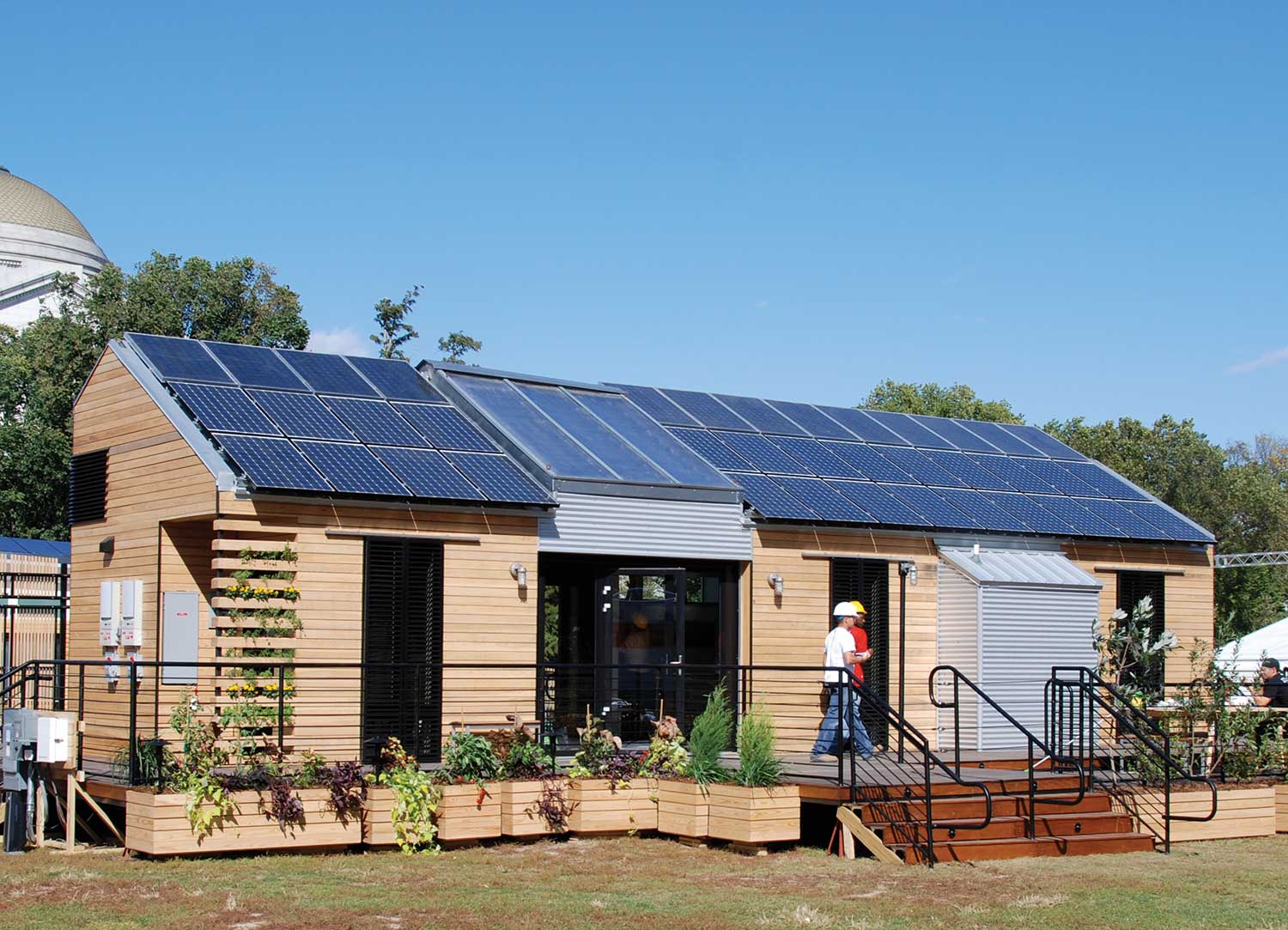
PV Systems. In general, PV systems convert sunlight (solar energy) into electrical energy that can be used to power various types of loads. In recent years, the most common type of PV system has been the utility-interactive PV system. This utility-interactive PV system consists of a PV array (a number of PV modules connected together) and a device called an inverter which converts the direct-current (dc) output of the PV array to alternating current (ac) that is compatible with the ac current that flows from the utility to power houses, commercial buildings, and industrial facilities. See NEC Figure 690.1(b).
The inverter ac output is connected in parallel with electrical loads in the house. The PV system ac energy flows either into the house loads or into the utility or both depending on how much PV energy is being generated at any particular time during the day and what loads are turned on in the house at that time. In periods of low solar energy (sunlight), and at night when there is no solar energy, the house loads would be supplied electricity from the utility. During the day, depending on the size of the PV system, the weather, and the loads that are being used, the PV system may provide sufficient energy to power all of the loads in the house or just some of them. The utility would supply the remainder. In other cases, a large PV system may be generating more power than the house loads can use, and the excess will be sent to the utility.
In all cases, for the utility-interactive PV system to operate, the utility must be connected to the house, be turned on, and be within certain specifications of frequency and voltage. The operation of a utility-interactive PV system is fully transparent and operates without user intervention, seamlessly and automatically supplying the loads in the house with energy from either the PV system or the utility. Off-grid PV systems (in use since the 1970s) have no connection to the utility electrical system. The dc currents from the PV array are used to charge batteries. An inverter called a standalone inverter then converts the dc energy in the batteries to ac energy that could be used to power house loads or devices like lights and water pumps used in remote farming applications. Off-grid PV systems are still in wide use throughout the country where power is needed in remote areas far from the utility grid. Such applications would include hilltop mounted telephone and data relay stations, oil and gas well monitoring, and remote homesteads.
In relatively recent times, the utility-interactive PV system and the standalone PV system have been merged together to make a utility-interactive PV system that has standalone capabilities. A multimode inverter is used with batteries to store energy from either the PV system or the utility grid and this inverter can supply power from those batteries to the house loads in the absence of the utility system. This is currently a very popular system in parts of California where the utilities are shutting down the electrical power grid in high-wind conditions to minimize the possibility of starting forest fires from arcs and sparks originating from the high voltage transmission lines. Other PV applications using batteries provide energy storage to offset peak loads or to shift PV energy from the day to the nighttime to assist in reducing utility bills.
The PV Module. The PV module generates electricity from sunlight, and those interested in the details of this process are referred to a good physics book. PV modules are usually made up of a collection of PV cells that are connected in series and/or parallel to provide the desired voltage and current from a particular module. PV modules used in power generation for residential, commercial and utility-scale PV systems may have 30, 36, 60, 72, or even 96 individual cells. Historically, the most common material used to produce these cells has been silicon, which is treated with various chemicals to provide the photovoltaic properties. These cells may be connected in series to obtain the desired output voltage. They are connected in parallel to increase the output current. Output voltages may nominally be 12, 24, and about 52 volts. Power levels in early PV modules were in the 20 to 30-watt range. However, current modules may produce 100 to 300 watts and higher depending on the size of the PV module.
Off-grid PV systems will typically have batteries operating at 24 or 48 volts, and PV modules can provide that voltage by connecting the modules in series to get the necessary voltage to charge the batteries. The modules may be connected in parallel after being connected in series to deliver higher currents to the battery charging system.
Utility interactive PV systems, on the other hand, operate with inverter dc inputs of hundreds of volts in residential systems, up to 1000 volts in commercial systems, and up to 1500 volts in utility-scale systems. PV modules producing various lower voltage levels are connected in series to achieve these higher voltages.
Power Outputs. AC power outputs and residential size systems may range from around a thousand watts to 10,000W (10kW) or more. Commercial PV systems typically start around 10kW and possibly go to several hundred kilowatts. Utility-scale systems are usually in the hundreds of kilowatts to the megawatt (MW) range, with many of the larger ones putting out 500 MW or more. One of the largest utility-scale systems is in China and is rated at 1850 megawatts of power.
Energy. Power is not the only requirement for using electricity. Energy is needed. And loads use energy by using power (watts) over a period of time. A 100 W light bulb (in the ancient days of incandescent lighting) operating for 10 hours would use 1000 watt-hours (100 W x 10 hours = 1000 watt-hours) of electricity or 1 kilowatt-hour (KWH) of electricity. A PV system rated at 10,000 W (10 kW) ac output would produce that full 10 kW only under conditions of bright sunlight. In the sunny Southwest, bright sunlight may exist on an annual average for about six hours per day. So, a 10 kW PV system could generate 60 kWh per day (10kW x 6 hours = 60 KWH), and in a utility-interactive PV system that 60 kWh per day could offset some or all of the energy used by the electrical loads in a house.
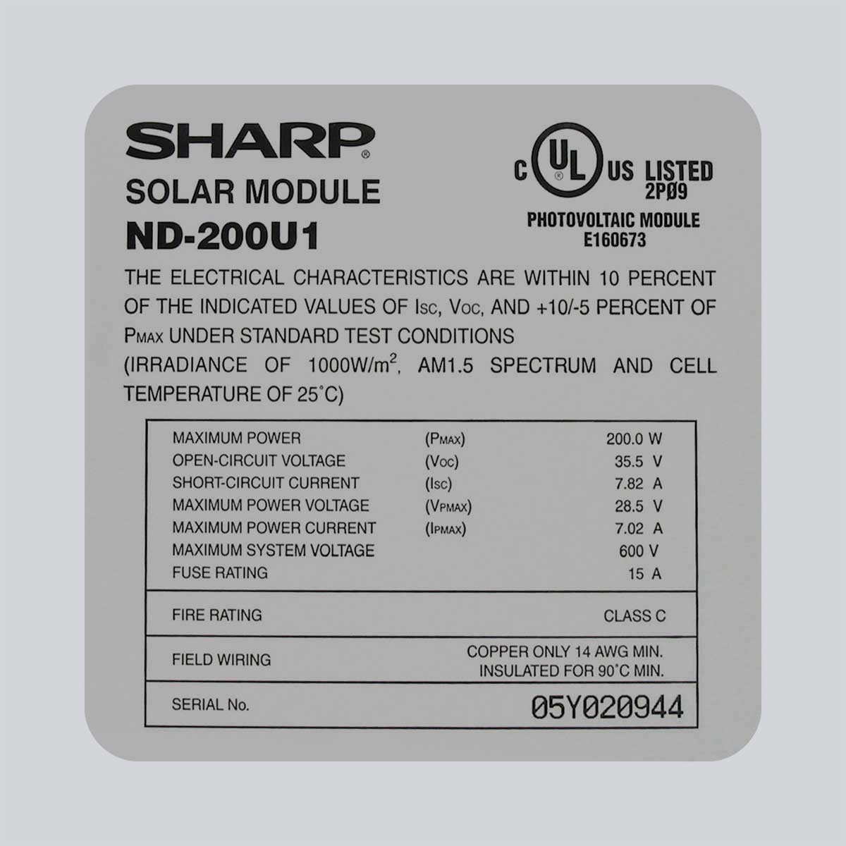
Specifications. Each PV module has a label affixed to the back that will contain the electrical specifications of the module (photo 1). The label will also include the manufacturer’s part number and a certification mark that the module has been evaluated and certified to Underwriters Laboratories Safety Standard 1703 for PV modules (this is a US requirement and may be different in other countries). The electrical specifications have been determined by the manufacturer in a laboratory, and a +/-percentage is associated with the power output. These specifications and numerous other safety-related requirements are verified by an independent, third-party testing organization known as a Nationally Recognized Testing Laboratory (NRTL) such as Underwriters Laboratories (UL), CSA Group, Intertek’s ETL or TÜV Rheinland. Inverters, dc PV combiners, and charge controllers must also be evaluated and certified for safety by these same organizations but, using UL Standard 1741. See NEC Section 690.4.
The module specifications of rated power output and voltage and current at that power and an open-circuit voltage and a short-circuit current are measured at a set of standard test conditions (STC). Standard test conditions represent a bright sunny day with a sunlight intensity (irradiance) of 1000 watts per square meter (W/m2) and a cell temperature of 25°C (77°F). In bright sunlight, in the outdoor environment, the PV module may operate considerably warmer than 25°C (77°F). And to address this operational reality, an additional set of parameters called the NOCT (normal operating cell temperature) parameters may also be provided in the module literature or the instruction manual. These parameters indicate the module performance at an irradiance of 800 W/m2, a 20°C ambient air temperature, and a one-meter per second (m/s) wind blowing across the module. Under these conditions, the module cells will operate hotter than it would under the STC test, and the module power output will be lower.
LOOKING DEEPER
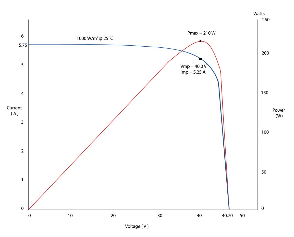
PV Module Details. The PV module delivers power in a manner unlike other power outlets that are familiar such as batteries and an ac electrical outlet in a house. The PV module provides power (voltage and current) based on the load that is connected to it and of course, the intensity of the sunlight falling upon it. Power (W) can be calculated by measuring the voltage (V) in the circuit and multiplying it by the measured current (I) in a circuit (W= V x I). If the module is put in bright light (1000 W/m2) and held at a cell temperature of 25°C (this may require using special air conditioning equipment), a voltage measurement on the module terminals with no current flowing would yield the open-circuit voltage (Voc) specification.
Under similar conditions, an ammeter attached to the same terminals would indicate the short-circuit current (Isc). Since power equals voltage multiplied by current, there would be no power flowing at either of these measurements because one of the factors, either voltage or current, would be zero. A graphical representation of the output of a PV module is useful in seeing this power output relationship in terms of voltage and current. This graphical relationship is called an IV curve and frequently appears in the module literature. See figure 1. The curve is generated by applying various loads (from an open circuit to a short circuit) to the module while holding the temperature and the irradiance constant and measuring the voltage and current at each load.
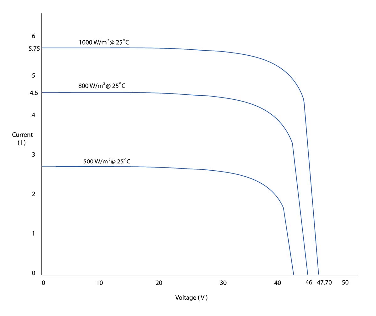
The output of a PV module is, of course, proportional to the intensity of the sunlight and figure 2 shows this information on an IV curve. The output of the PV module is also inversely proportional to temperature and figure 3 shows this relationship. This information will be used as we get deeper into the Code requirements for PV systems.

As a safety concern, it should be noted that PV modules and strings of series-connected modules can generate voltages that can be deadly at very low light levels, such as those that exist before sunrise and after sunset. Proper protective equipment should be used at all times when working with energized electrical systems.
Mounting PV modules. PV modules must be securely attached to the supporting structure. In residential systems, that supporting structure is usually the roof, however in commercial systems or utility-scale systems, the PV array may be on a carport or ground mounted. For mounting, the modules have four to six factory-drilled holes in the back of the frame. During the certification evaluation process, these mounting holes are used according to the instructions provided with the module to ensure that no structural damage will occur to the module when it is subjected to high wind loadings and other mechanical loadings such as those provided by snow or ice. Many PV modules are currently mounted using clips that fit over the module frame and secure it to a racking system, which in turn is fastened to the structure of the building (photo 2).
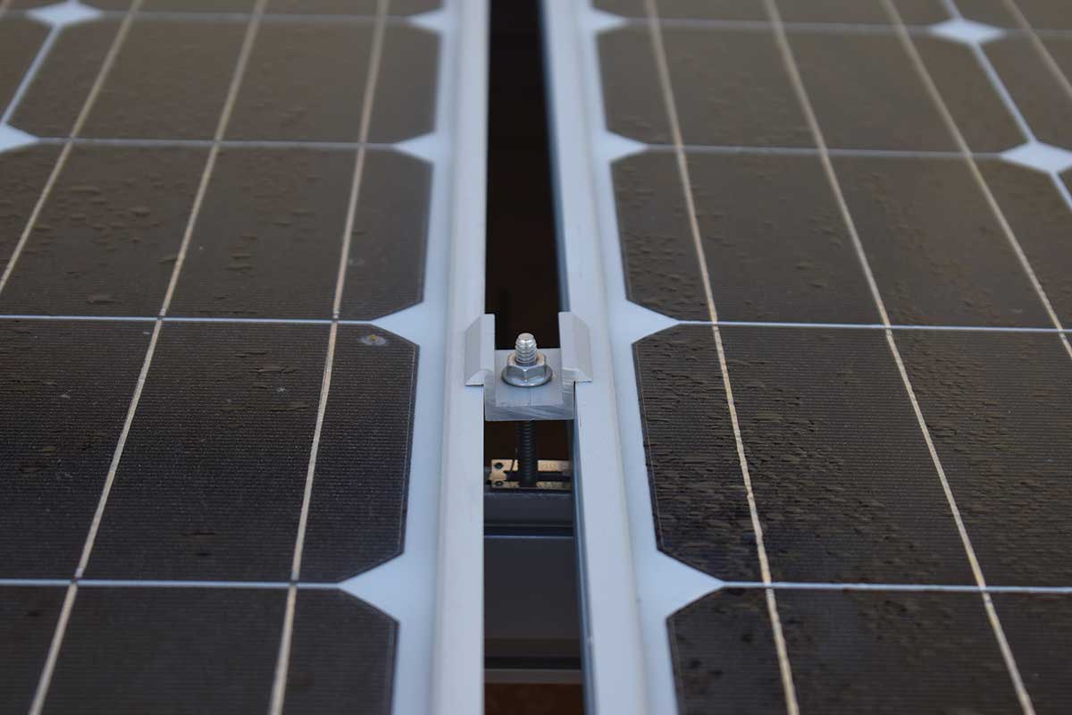
In order to be able to use these “top clip” mounting systems, the module instruction manual must show the areas on the module frame which have been evaluated for the use of such clips. If the module instruction manual does not show designated areas for top clip mounting, then that mounting method cannot be used with that particular module. The top clip mounting system is usually part of a racking system that has been evaluated and certified to Underwriters Laboratory Standard 2703. Although the NEC does not specifically require a certified and evaluated racking system, they are frequently used in residential applications because they speed up the installation by providing a quick module mounting system and a fast method of achieving the equipment grounding connections for each module required by the Code. Because many roofs use relatively thin 7/16” to 9/16” decking, it is preferable, in nearly all cases, to fasten the PV mounting rack directly to the underlying rafters or trusses, and not just to the decking (photo 3). The top clip mounting devices may also provide equipment grounding between the module frames and the rack (photo 2).

AC PV Modules and Microinverters AC PV modules (690.2, 690.6) are a factory assembled combination of a standard dc PV module and a microinverter mounted on the module. These factory assemblies, evaluated and certified as a single unit, provide an ac output (usually 240V) directly at the AC PV module. This eliminates the high voltage dc wiring and a dc combiner box typically used on standard PV systems with string inverters and isolates shading or other problems in a single module to that module. PV arrays using strings of series-connected dc modules can have large reductions in power when only one module in the string is shaded or otherwise has problems. Microinverters can be used with dc PV modules to achieve the same benefits as an AC PV module, but two components are involved that must be mounted and connected (photo 4).
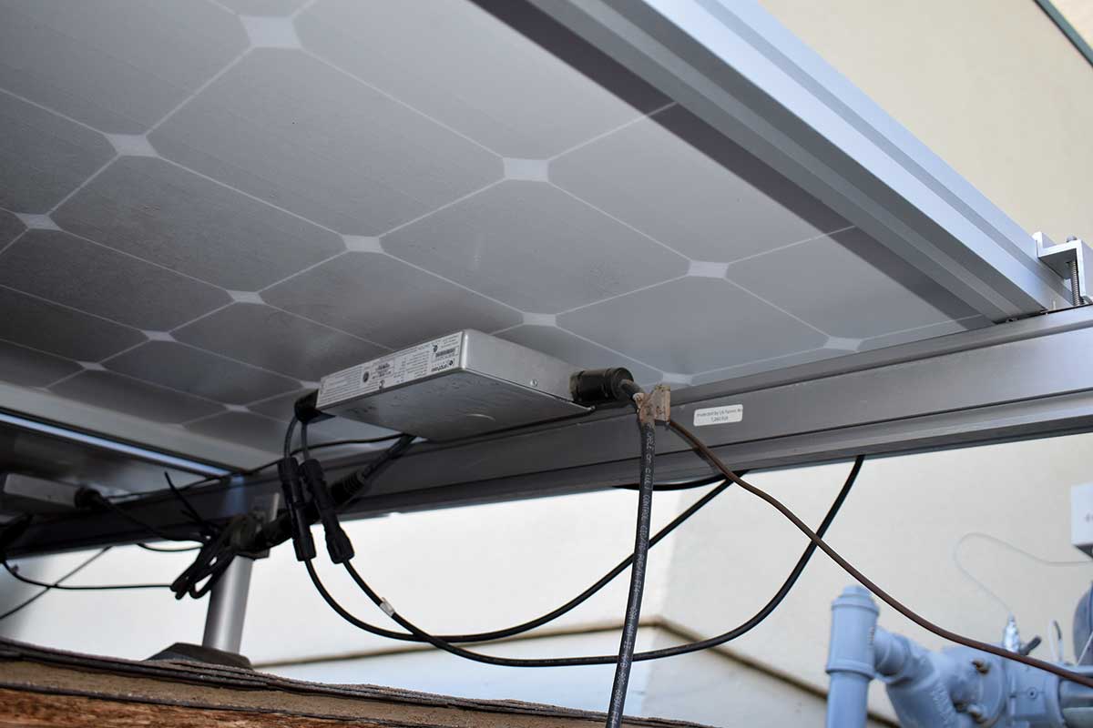
Again, the output of the microinverter is typically 240V and a factory-manufactured trunk cable with connectors is used to collect power from each microinverter and run it to the ac premises wiring system. The trunk cable is rated for exposed outdoor installations and must be secured to the modules or the racking system. At the point where the trunk cable may be required to enter the house, it must be transitioned to a wiring system appropriate for interior power wiring. In cases where there are several sets of trunk cables, they are combined in an ac combining panel, which usually has circuit breakers. Care must be taken on where the circuit breaker panel is mounted. It should not be subjected to excessive heat from direct solar exposure. Always verify that this equipment is listed and suitable for the outdoor environment.
DC-to-DC Converters. Another variation of the PV system uses a standard dc PV module coupled to a dc-to-dc converter, which has a dc output and is connected in a series manner with other dc-to-dc converters on other PV modules. DC-to-dc converters isolate the module dc output from the string dc circuits. The module dc output characteristics must match the input characteristics of the dc-to-dc converter, and the dc specifications of the modules are typically ignored at this point. The dc-to-dc converter output specifications, when connected to a matching string inverter, have completely different operational specifications than the PV modules, and the Code requirements for the dc output of the PV modules do not apply. The inverter communicates with the dc-to-dc converters controlling their voltage in a way that keeps the total string voltage within the maximum input allowance of the string inverter. With these systems, it is necessary to carefully follow the requirements in the instruction manuals associated with the converters and the string inverters to ensure that they are installed correctly.
Connector Conundrum. Many of the connectors attached to the cables on PV modules are known as a type MC-4 connectors. The MC-4 connector was originally developed and patented by Multi-Contact Corporation (Stäubli Electrical Corp in the US). Connectors made by other companies that resemble the MC-4 connector may appear to be mechanically and electrically compatible (photo 5). However, these alternative type MC-4 connectors have not been evaluated or certified for complete compatibility with each other or with the original MC-4 connectors.
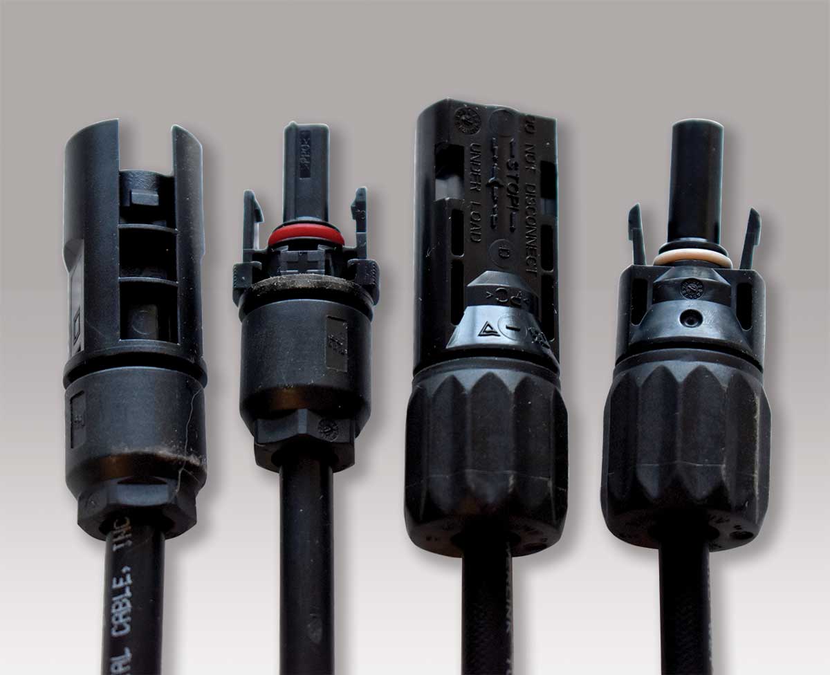
The plastics may be different, the metal of the contacts may be different, and the plating on the contacts may be different. These differences in materials can result in a shortened lifetime of the mechanical and/or electrical connection. The PV module instruction manual and/or the PV module label is required to list the manufacturer and part number or series of the connector being used on that PV module. To meet the requirements of the evaluation and certification/listing on the module, an identical matching connector from the same manufacturer must be used when extending the module cables (e.g., at the end of a string). This requirement creates significant problems for the installer because each of the numerous PV modules being made by different manufacturers, especially from China, has connectors from different manufacturers. And it has been reported that even a single shipment of modules may have different connectors on the same modules within the shipment. And it creates problems for the inspectors since the connectors are hard to get access to (and read) on the installed PV array where the modules are mounted close to the roof. During the permitting process, the installer should provide information on the connectors being used on both the PV modules and any extension cables attached to those modules.
Summary
A PV system is relatively simple in concept, but after the NEC requirements are added for safety, the execution of the system requires considerable attention to detail. And as the complexity of the technology increases, more and more attention will have to be directed to the instruction manuals provided with the equipment.