Recent weather events in the winter and spring of 2022/2023, including heavy and continuing rains, flooding, heavy snows, tornadoes, forest fires, hurricanes, tidal surges, and high winds, have resulted in very large numbers of people in the affected areas being without electrical power for days and sometimes weeks or longer. Due to climate changes, these weather events are expected to continue and more than likely become more frequent and worse, according to climatologists. Over the decades, residential design and construction practices have dealt with more benign climates and weather events, and dwellings and other buildings have been built in areas not currently suited for such construction.
These power outages, while being corrected as rapidly as possible, have given significant impetus to the installation of photovoltaic (PV) power systems with and without energy storage. Many jurisdictions are being overwhelmed with permit applications dealing with the installation of utility-interactive and utility-interactive with energy storage PV systems. Furthermore, there are thousands of gigawatts of large utility-scale PV and wind projects waiting a year or more for a connection permit to the utility grid. Many are being canceled due to the delays.
We should also keep in mind that technology is advancing, and we will see, in the near future, a proliferation of electric vehicles (EVs) throughout the country and throughout the world. More than a few of the charging stations associated with these electric vehicles will be combined with PV arrays to reduce the load on the utility electrical transmission and distribution infrastructure.
Additionally, plans are currently underway to have electric vehicles, when parked, send power to the utility grid or to the accompanying dwelling, energy storage systems in dwellings send power and receive power from the electric utility, and combinations of these various electrical power flows. These energy flows will be determined by various schedules based on the utility’s need for energy and the ability of the residential energy generation (PV) and storage (site energy storage systems) and EVs to supply that energy or reduce the demand for energy on-site. Both the utility and the residential customer will have emergency override capabilities for the preplanned schedules. It is anticipated that the customer will be compensated for these services. This complex energy flow control system will necessitate that significant amounts of additional electrical control devices will need to be added to the electrical system of dwellings that have EVs, PV systems, and energy storage systems.
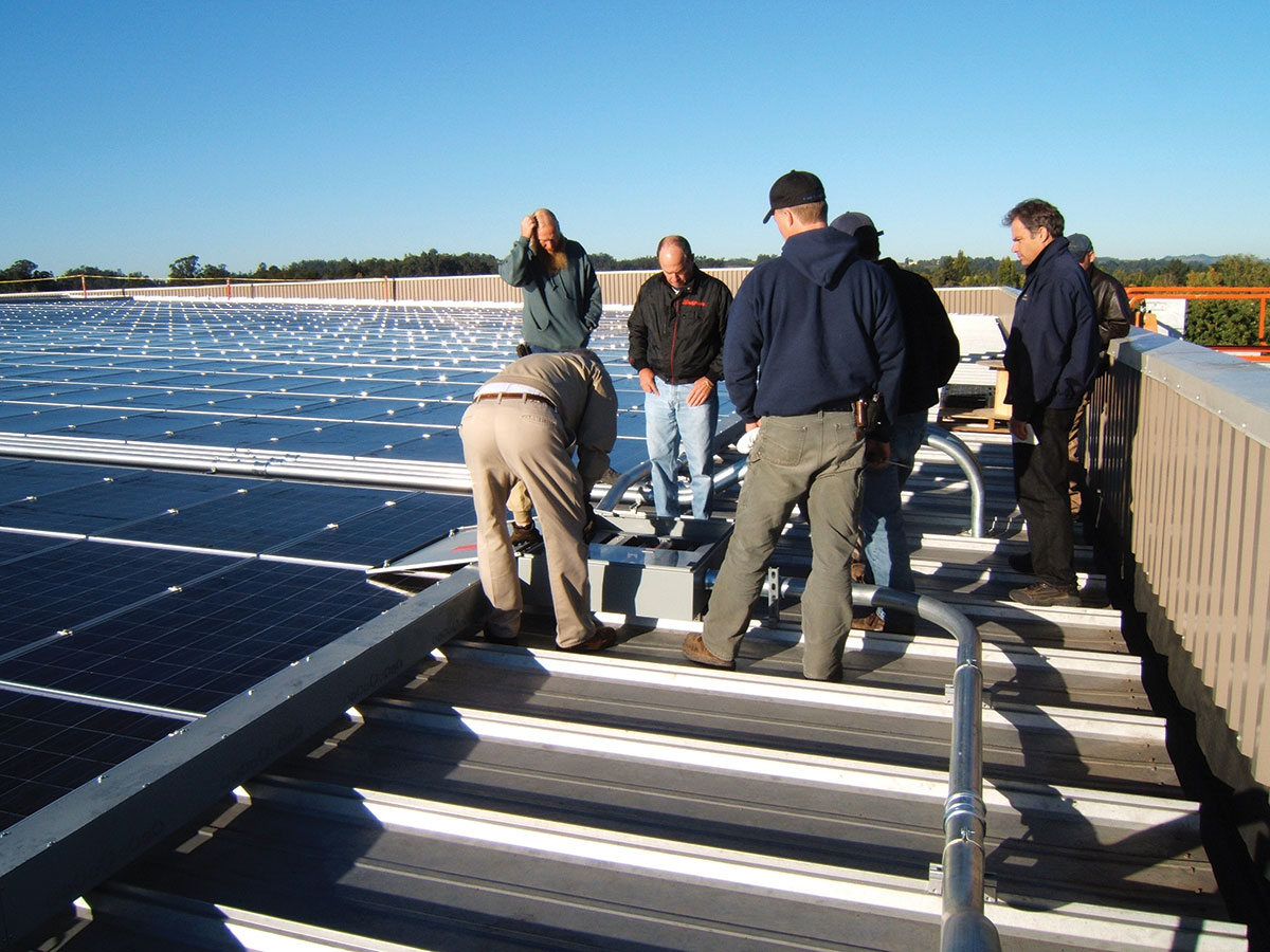
This article will briefly outline a suggested process for handling permit applications, plan review, and the inspection process for PV systems. In terms of full disclosure, I am an electrical engineer and not a licensed PV Installer or a licensed Electrical Inspector. However, over the last 34 years in the PV industry working at the research and development level, I have inspected (for NEC compliance) and tested hundreds of PV systems, both small (less than 5KW) and large (over 1 MW) throughout the country. I have also performed hundreds upon hundreds of plan reviews for various organizations, including utilities, government agencies, and PV installation companies, as well as inspection agencies.
It is acknowledged that each jurisdiction will have its own process for handling permit applications, plan reviews, and inspections of PV systems. Small jurisdictions may not have the budget for a dedicated plan review person, and the permit applications may be handled by administrative staff with no technical knowledge. Online automated systems are being developed to perform the permitting and plan reviewing task, which will be discussed later in this article.
Permitting and Plan Reviewing
Ideally, the permitting and plan review processes should be combined so that an installation permit is not issued until detailed plans have been submitted and approved through a plan review process. I realize this is not always possible, but it is something that we should all strive for. Where a dedicated plan reviewer is unavailable, the electrical inspector should spend time in the office reviewing the submitted plans before a permit is issued.
Here is a list of items that should be included in a permit application and reviewed by a Plan Reviewer before any permit is issued. In jurisdictions using an online submission process, these items may be submitted electronically in PDF format.
Full, three-line diagrams of the electrical installation and other materials showing:
- All conductor types, sizes, and installation methods and locations. Temperatures experienced in each conductor location include heating from heat bubbles on roofs, solar exposure, and normal conditions of use. Ampacity calculations for each conductor run.
- Ratings and connection location of all overcurrent protection devices and disconnects. Specification sheets for these overcurrent protection devices and disconnects.
- Where multiple NEC requirements may cover component ratings, the specific Section of the NEC should be cited that has been used in each case.
- PV module specification sheets, expected lowest cold-weather temperature at the installation site, calculations showing cold-weather maximum voltage, and maximum currents in each single circuit and in paralleled circuits.
- Details of PV module mounting and grounding to a racking structure and instructions showing that the module grounding method has been evaluated and listed as compatible with the racking structure. Provide indications that the racking structure is capable of withstanding wind and snow loading in the installation area. Also indicate that the racking structure weight, including module weight and predicted snow loading, will not overstress the underlying roofing structure.
Full specification sheets and installation manuals for all electrical equipment, including PV modules, inverters, charge controllers, separate batteries, DC-to-DC converters, systems with energy storage, and DC combiners.
The array location on the building roof should be diagrammed, showing the required setbacks from the edges of the roof as required by building codes. Location and content of all required field-installed labels.
Plan Review
Because the installation of PV systems involves both mechanical, fire, and electrical requirements, the Plan Review Office should have full copies of all those codes and regulations that are in effect in the jurisdiction. These might include the National Electrical Code (NEC), the local modifications to that code, ICC International Residential Code, and any other codes or requirements that might be applicable.
The Plan Reviewer has the primary responsibility of looking at the submitted plans and evaluating all submitted material for compliance with the appropriate codes and standards. This will include verifying the correctness of any calculations, the appropriateness of any temperatures used in those calculations, and the correct application of the various specifications associated with the PV modules and other equipment being installed. These calculations should include ampacities and temperature corrections as well as other conditions of use for each conductor in the temperature environment (s) that the conductor will experience. Also, the expected low temperature for the installation location should be examined for correctness, and the calculation for DC maximum system voltage should be correct and compliant with the maximum system voltage for any equipment being exposed to that voltage.
The Plan Reviewer should also review the installation manuals for the equipment and confirm that that equipment is being installed in compliance with the instructions in those manuals and the appropriate codes [NEC 110.3(B)]. This is particularly important as the systems become more complex with energy storage (batteries-either internal to the inverter system or external).
The PV module mounting and grounding procedures used should follow the instructions provided in the installation manuals for the racking system and the PV module. The mounting structure or racking system wind loading and snow loading requirements are met, and the array setbacks from the roof edge meet fire codes.
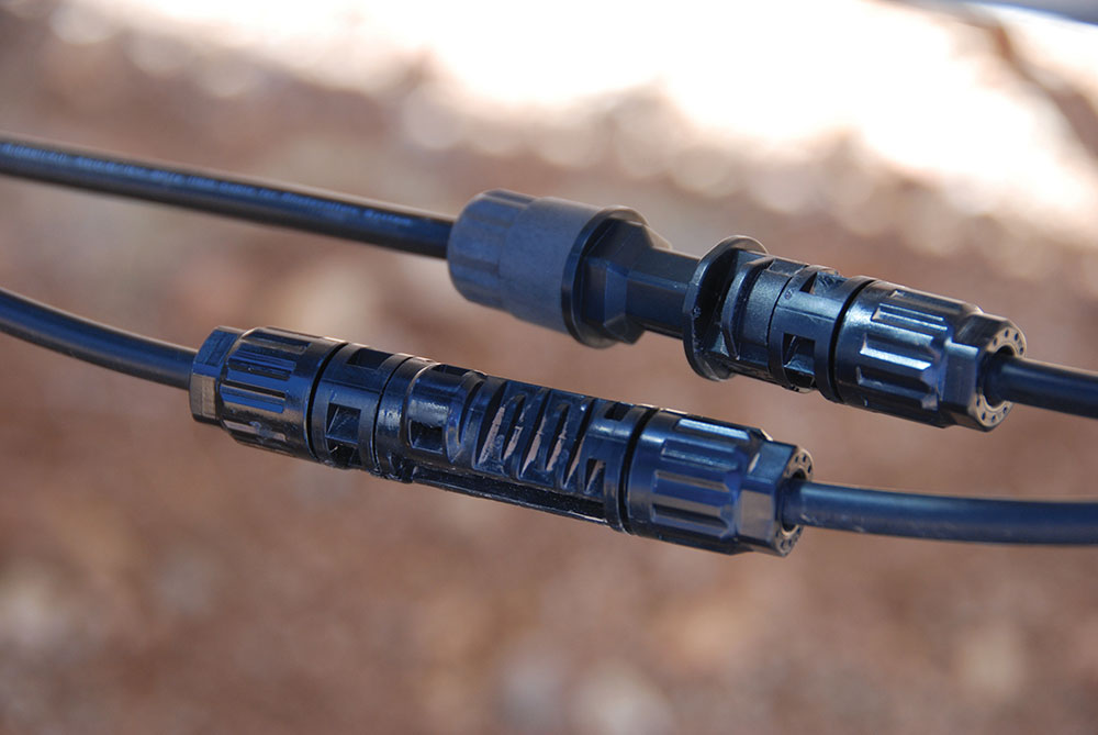
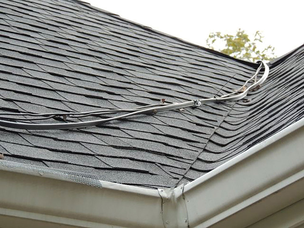
Where connectors are involved in connecting the module string outputs to the string conductors running to the combiner boxes or to the inverters, the pairs of male/female connectors at the ends of the strings should be confirmed to be from the same manufacturer and of the same production series. The use of MC 4 connectors identified by type only may be insufficient to ensure full electrical compatibility as required by Underwriters Laboratory Standards and the NEC [690.33(C)] [see photo 1].
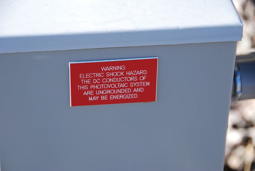
The plan should also include the content and locations of any required labeling throughout the system (photo 2). In addition to the required labeling, the location of disconnects, load centers, and other equipment should be marked on the plans.
Inspecting PV systems
Assuming that the plan review process has been completed and any issues noted have been returned to the installer for correction and the corrected plans have passed review, and an installation permit has been issued, the inspection may proceed.
The inspection will have two parts. The first is an examination of the physical/mechanical installation of all equipment. The second is an electrical examination of the system as it is turned ON and OFF when connected to the utility. It is noted that in some jurisdictions, this may require two visits to the site because some utilities will not issue an interconnection agreement until the initial inspection has been completed. The second operational part of the inspection cannot be done until the system is connected to the utility. In some jurisdictions, with utility cooperation, both inspections can be done on one site visit if scheduled correctly.
Physical Inspection. The Inspector may now assume that the permitted system (at least on the plans) meets all applicable codes and standards, and regulations and that, as the plans show, it can be safely installed and operated. The Inspector now has several functions which cannot be accomplished through the plan review process.
Note: Rooftop access may not be required where the local jurisdiction does not permit it for safety and/or liability issues. In those cases, the installer should provide close-up, detailed photographs of the required areas. Where rooftop access is desired for the inspection, full safety harnesses and fall protection should be used, particularly on sloped roofs.
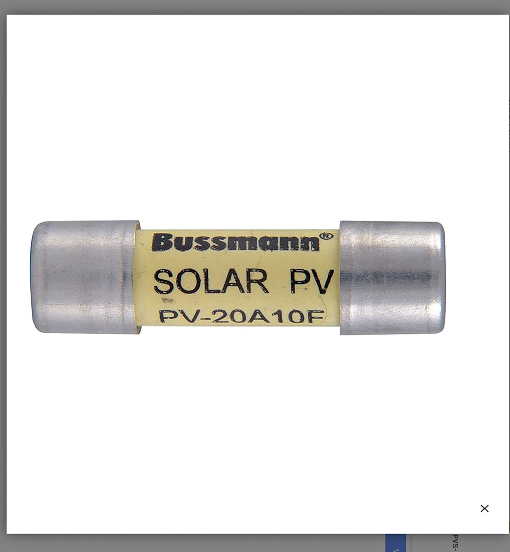
Is the equipment that has been installed on site the same as the equipment that has been specified in the plans? This includes all conductor sizes and types, mounting systems, PV modules, inverters, DC combiners, and other devices such as load centers, overcurrent protection devices, disconnects, and all required labels. Are fuses used in the DC PV circuits listed as PV or Solar fuses? See photo 3.
Are the actual installation practices for module attachments to the racking structure and module grounding to the racking structure followed according to details in the plans or in the instruction manuals for these pieces of equipment?
Are the PV modules and the various pieces of other equipment installed in a manner that shows good workmanship to the extent that the equipment will resist environmental stresses, including wind and snow loading, sunlight exposure, and various other mechanical stresses? The installer should be required to explain to the inspector how the PV racking system is attached to the building structure, including attachment to roof trusses through the roof sheathing and how those trusses have been located.
Does the installer have appropriate torquing equipment/tools to install conductors that have been stripped of insulation? These conductors would need to be installed, and the terminals torqued in most cases in load centers and in DC combiners, and inverters, as well as various disconnects where required. The torquing tools should also be used to torque items like battery terminals and other mechanical attachments.
Exposed conductors should be attached to the module frames or racking structure with attachments that will resist high levels of temperature and sunlight exposure. See photo 4. Plastic wire ties must be listed for extreme outdoor conditions, including high temperatures (90°C or better); sunlight resistance (SR) may not be sufficient. If not so listed, they may last for only a year or so, especially in the hot Southwest climates.
Conduits and exposed conductors on the roof and in other exposed locations should be firmly and properly attached to the roof so that they will be damaged by wind or snow loading, or moving ice dams.
The location and wording of each required label, including hazard warning labels, should be verified.
Electrical Operational Inspection. This inspection will be carried out after the utility has issued an interconnection agreement and the system has been connected to the utility. Note, these electrical tests are not performance tests but are safety tests related to Code requirements for a safe installation.
Any operation of the various system controls and measurements of the various electrical voltages and currents should be made by the installer and observed by the inspector. Proper safety equipment and tools, and procedures should be used.
The main service disconnect, or the AC PV disconnect, should be operated. When turned ON from an OFF position, the five-minute delay built into the inverter as part of the anti-islanding system in the inverter should be verified by measuring inverter status indicators and the current flow from the inverter to the utility service. This will require an AC ammeter; preferably a clamp-on ammeter.
For rooftop-mounted PV systems, the PV Rapid Shutdown System should be initiated with each of the marked initiation devices, and the required DC-controlled voltages outside the array should be monitored to indicate that they go from the high voltage condition to the controlled 30 volts within 30 seconds. This voltage is most easily monitored at the input of the inverter or on a DC disconnect at the inverter. Where a DC combiner has been installed, the PV Rapid Shut Down System initiator should be activated while monitoring positive-to-negative and line-to-ground string output voltages to ensure that they are reduced to the 80 V required within 30 seconds within the array. Optionally, where there is no DC combiner, an adapter made from Type MC 4 connectors allowing access to the positive and negative conductors within the array can be installed in a string output circuit and monitored for the 80 V controlled voltages within 30 seconds.
Where the system has been installed on a building requiring NEC Section 690.11 Arc Fault Circuit Protection (DC) and the device providing that protection or the inverter has a self-test or manual-test function, that function should be observed or tested per the manufacturer’s instructions.
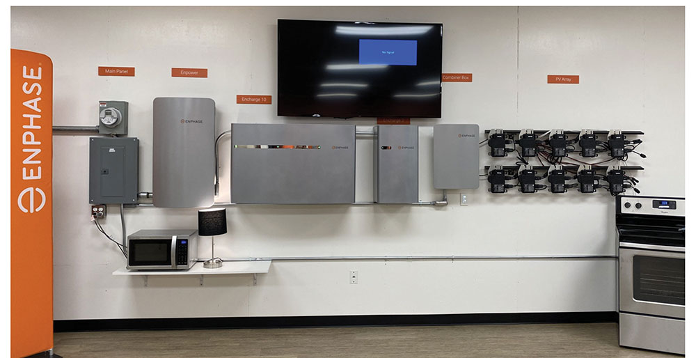
The operational testing for systems with energy storage combined with utility interactive inverters can be more complex (see photo 5). The instruction manual for such systems should be verified and followed for any initial or operational testing. Since the complex control systems in these energy storage systems may electronically control currents in a manner that prevents busbar overloading, a clamp-on AC ammeter may be required to monitor current flows as the tests are conducted. Such testing should reveal any incorrect initial setup (programming the set points in the software), initial connections, and any improperly rated components.
A final check with the utility-interactive system fully turned on and connected to the utility should be made by observing DC current flow from the DC array output to the inverter and AC current from the inverter output to the utility under sunny conditions.
On-Line Automated Permitting and Plan Review
The National Renewable Energy Laboratory (NREL) has developed an online permitting and plan review process which has, in many cases, considerably speeded up these activities. Licensed PV designers and installers, and inspection organizations may gain access to the APP. This application is called “SolarAPP+” and here is a link to a description of the application.
Further information may be obtained at:
https://www.nrel.gov/docs/fy23osti/85010.pdf
Summary
The process of permitting, plan reviewing, and inspecting PV systems is the key to safe systems and to enhance the durability and longevity of these systems. Although the NEC establishes safe installation requirements and does not require the verification of long-term performance or durability, the process that is currently required as described above will help to ensure that the systems from an equipment installation point of view will be safe and last as long as possible.