Before we progress further into the electrical requirements of the National Electrical Code (NEC), let’s investigate some of the factors involved with a photovoltaic (PV) power system that deal with the durability and the safety of the installation. Some of these are specifically spelled out in the Code, but others are based on common sense and experience over time. Although the NEC does not specifically deal with the long-term durability of a PV system installation, it is evident throughout the Code that many of the requirements are based on ensuring durability in a harsh outdoor environment. Such requirements as good workmanship (not well defined) and the spacing of conduits and conductor supports indicate that some attention has been given in writing the Code to the system’s durability. And when durability is not built into the installation, long-term safety may suffer.
The module and string voltages and the inverter DC inputs are critical issues since we will be experiencing widely varying weather conditions throughout the country in the years and decades ahead.
The Basics
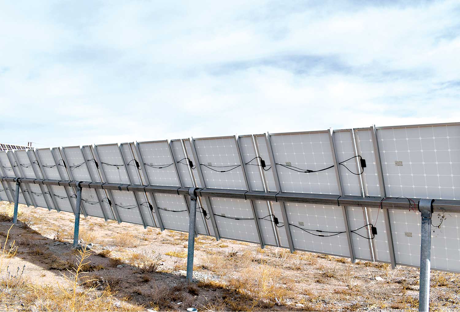
Secure Mounting. PV modules are attached to racks, and these racks are attached to roofs or ground-mounted. In both cases, the modules must be securely attached to the racks using the instructions provided in their installation manuals and the racks attached securely to the roof or the earth. For a listed rack assembly using listed mounting brackets, instructions should be provided for installing these mounting brackets securely to the roof. However, some racking systems come without mounting brackets, and the selection of those brackets is left up to the installer. High winds during unexpected thunderstorms may exhibit significant uplift and down lift forces on the PV modules putting all attachment points and devices to severe cyclical loading. Furthermore, grounding the PV modules and the rack are inherent activities associated with securely mounting the modules and attaching the rack to the roofing structure.
Cable and conduits in the outdoor environment must also be securely attached to the various supporting structures per NEC requirements.
Looking Deeper
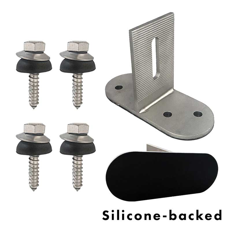
Module to Rack Mounting and Grounding. Many manufactured racking systems are listed to Underwriters Laboratories (UL) Safety Standard 2703 for both mechanical integrity and electrical grounding the modules. In many of these racking systems, the module mounting system will consist of a set of top clips that hold the module to the rack (photo 1). For these top clips to be used, the module mounting instructions must show areas on the module frame where the top clips can be attached/clamped. In the best situation, the racking instructions will indicate that those specific modules have been evaluated with that rack.

In many racking systems, the top clip mounting system will also serve to ground the modules to the rack, and there will be only one point on the rack where a single equipment grounding conductor is installed for the set of modules attached to the rack.
If neither the module instructions or the racking system instructions indicate that top clips can be used, they should not be used, and another fastening method must be adopted. In this case, the module mounting holes that are predrilled in the modules must be used to secure the modules to the rack, and this will normally require that the rack members be drilled. Although both the modules and the rack may be listed, the rack members are generally more robust than the module frame members, and it would be preferable to drill the rack because it would be a violation of the listing on the modules to drill holes in the module frames for either grounding or mounting. Existing marked holes in the module frame and the instruction manual for the modules must be used for both mounting and grounding where there are no provisions for top clips.
Where top clips are not used for mounting or grounding and a site-built racking system is constructed, each individual module must be grounded with some type of an equipment grounding conductor; usually, a copper conductor attached with an appropriate outdoor-rated grounding lug that can isolate the copper conductor from the aluminum module frame. It is generally not possible to use this custom-designed/site built racking system that has not been tested and evaluated, and certified (listed) for grounding as the grounding device for all of the modules attached to it
In cases where stainless steel hardware (screws, nuts, and lock washers) is used, it is recommended that an anti-seize compound be used on the threads to prevent threads from galling and seizing over time. Although not a specific Code requirement, this comes under the category of good workmanship and will facilitate the removal and replacement of modules later should that be necessary.
Rack to Roof Mounting. It is unfortunate, but true, that increasing costs of building materials, including plywood and OSB for roofing decking, have driven roofing contractors to use the thinnest sheets they can for roof decking while following the requirements of local building codes and passing local inspections. In some places, 7/16 of an inch of OSB is used on 24-inch on-center trusses for the roof decking. And in some locations, building styles do not make the trust locations visible from an attic or other location after the roofing materials have been installed. Furthermore, due to the slight warpage of the trusses and imprecise positioning, the trusses may not be exactly 24 inches apart. This requires that the trust locations be determined from above the roof after the roofing has been installed, and this may require approximate measurements and then test holes through the roof to determine the actual location of the trusses. Putting extra holes in a roof that are not used is a potential source of leaks in the roof, and each hole must be carefully sealed; sealed for the life of the roofing material.
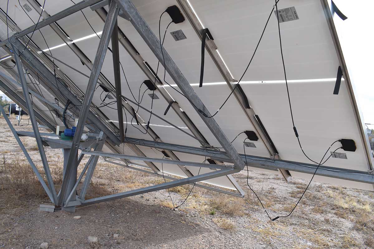
It is generally very important to screw (usually with lag bolts or engineered screws) the brackets to the trusses and not just to the roof sheathing (photo 2). Some (very few) commercially available brackets may have multiple screws suitable for attaching to the sheathing. These evaluated/certified/listed brackets may withstand the high winds that come with unexpected intense thunderstorms (photo 3).

Cable Management. The conductors between modules and from the end of the string of modules to a combiner enclosure must be properly secured to avoid damage from wind, rain, and snow loading. Depending on the cable type — single conductor or multiconductor — the attachment requirements to the rack or the building structure vary. Section 690.31 in the NEC has numerous requirements that apply to these outdoor PV circuits. One of those requirements, in 690.31(C)(1) requires that the single conductor cables shall be supported and secured at intervals not to exceed 600 mm (24 inches) by cable ties, straps, hangers, or similar fittings listed and identified for cable securement and support in outdoor locations.
Unfortunately, many PV installations are made with plastic cable/wire ties that, while evaluated certified and listed for ultraviolet radiation exposure [sunlight resistant (SR)], do not withstand the decades of high-temperature sunlight exposure associated with PV systems (photo 4). The testing involved in obtaining the SR marking consists of only 720 hours of accelerated ultraviolet (UV) testing in the lab. This is equivalent to only about 2 ½ years of outdoor exposure in a PV system in the sunny Southwest.
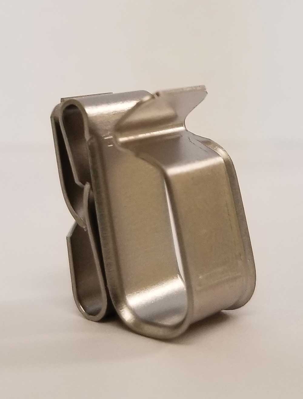
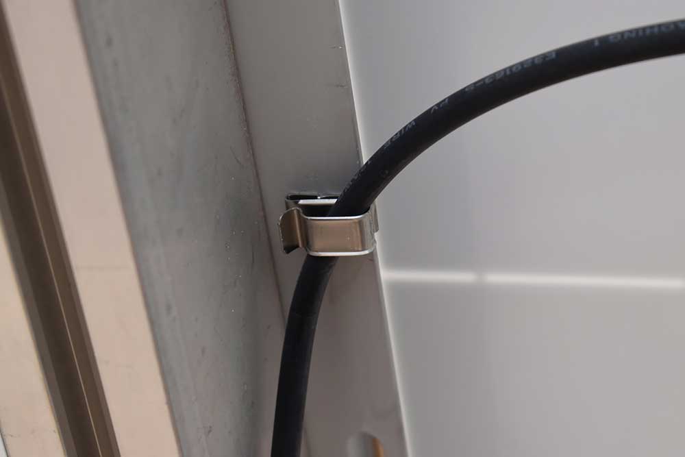
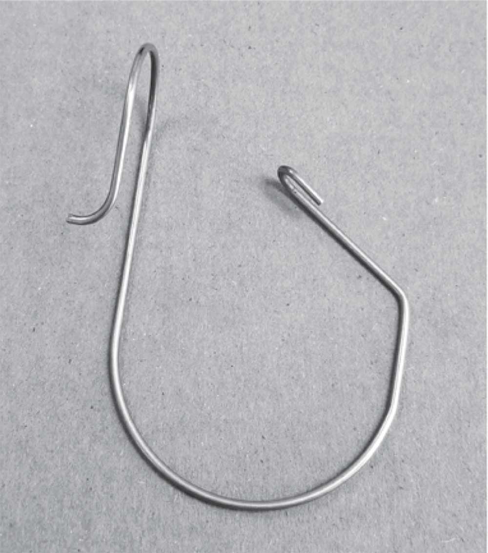
Fortunately, metal cable clips with rounded edges made of stainless steel are available in several configurations that will suffer no degradation over the life of the PV system (photos 5 and 6). Single conductor cables are bundled together in many PV installations as they are routed towards the DC combiner. Sometimes electrical tape or plastic cable ties are used to bundle these cables, and these devices deteriorate over the years. However, there are galvanized steel cable bundling devices that can bundle these cables together in a safe, durable manner (see photo 7). Keep in mind that the ampacity of these cables goes down as the numbers that are bundled together exceed even one for free air ampacity (Table 310.17) or three for bundled cables (Table 310.16).
Where conduits, usually EMT, are run across a roof they will be subjected to not only wind and heavy rain loading but also sliding ice dams as snowmelt freezes and unfreezes and large chunks of ice slide down the roof. These conduits must be secured per code requirements at the required intervals, and it is suggested that the conduit attachment devices be screwed into the trusses and not just into the sheathing. Also, keep in mind that per the 2020 NEC, if the conduit is closer than seven-eights of an inch to the roof, an ampacity temperature correction factor must be added. Of course, as mentioned in previous articles, if you’re on previous editions of the Code or desire a conservative installation, it might be wise to consider the multi-height temperature correction factors in those editions.
Module and String Voltages
The PV module’s output voltage depends on the amount of sunlight impinging on the front surface of the module, the cell temperature of the module, and the electrical load placed on the module. Temperature is a critical factor because the module output voltage varies inversely with temperature. As the temperature goes down, the output voltage increases. Modules are rated at a set of standard test conditions (STC), which include an irradiance (solar intensity) of 1000 watts per square meter (W/m2) and a cell temperature of 25°C (77°F). The module is loaded at its peak-power point to determine the peak-power (or max power) current (Ipp or Imp) and the peak or max power voltage (Vpp or Vmp) at STC. Also measured at STC are the open-circuit voltage (Voc) (no load connected to the module terminals) and the short-circuit current (Isc) (a short circuit connected to the module terminals). During the development of the module, the variations in open-circuit voltage, peak-power voltage, and short-circuit current are measured with respect to changes in temperature. These variations are expressed as temperature coefficients in the module datasheet. These coefficients are used to determine how the various module outputs vary with temperature. The results are used to design the PV system configuration starting with a set of selected PV modules, a selected inverter, and a general idea of the desired size of the PV system.
The PV inverter has a maximum allowable direct-current (DC) input voltage which cannot be exceeded without damaging the inverter. Examples of this maximum voltage (Vmax) may be 600 V, 1000 V, or 1500 V, depending on the intended application of the inverter and PV system. The inverter will also have a peak power tracking range where the inverter can extract maximum power from the PV array. That peak power point in terms of voltage varies due to environmental conditions such as temperature, clouds, sunlight intensity, and wind. Because of the variation of DC array voltage with temperature, that voltage must never exceed the inverter’s rated maximum DC input voltage. This will occur when the lowest expected temperature at the installation site occurs while the PV array is energized with sunlight. There are various sources of weather data that present the record low temperature at the site or the average winter low or trends in those data.
The PV installer must work with the AHJ to agree upon the expected low temperature for any particular site. This expected low temperature in conjunction with NEC requirements in Section 690.7 allows for the determination of the system voltage at that low temperature. The system voltage is determined by the module output open-circuit voltage at the lowest expected temperature and the number of modules connected in series in a string or source circuit.
This code requirement of “not damaging the inverter at low temperatures” comes from Section 110.3 (B), which requires that the module, inverter, and other listed equipment instructions and labels be followed. The maximum DC input voltage on the inverter will be clearly stated in the specification sheets and instruction manual for the inverter and, in some cases, on the inverter label.
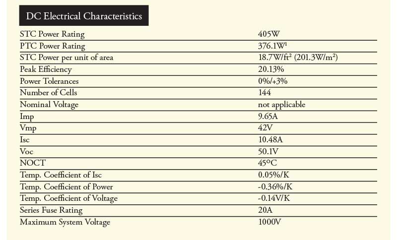
Typically, the problem is worked in reverse, starting with a specified maximum inverter input voltage of 1000 V, for example. We then look at the module specification sheet, in this case, the specifications for a JINKO 405 PV module presented in figure 1. Note that the open-circuit voltage Voc at standard test conditions is 50.1 V and that the temperature coefficient of voltage is -0.14 volts per degree Kelvin (also per degree Centigrade). However, this coefficient is for the change in voltage for the peak power point as a function of temperature and will be used below. From another source (the factory website), we find that the coefficient for a change in voltage as a function of temperature for Voc is -.18 volts per degree C.
For the installation site, the average lowest Winter temperature during recent years has been relatively consistent at 14°F. PV installers and AHJs have used this expected low temperature for several years in determining the module DC voltage output under cold weather conditions. However, three years ago, an exceptionally cold air mass covered the region, and the temperature was at -2°F for several days.
AHJs should be familiar with the process shown below because it pays to check the calculation to see if it has been performed correctly. Another option for an approximate number is to use Table 690.7(A) in the NEC.
However, this table is an average for crystalline and multicrystalline/polycrystalline PV modules, and newer crystalline and polycrystalline PV modules may not have the same temperature coefficients that the table was based on.
The designer of this new PV system elected to use the -2°F (-19°C)‚ as the expected low temperature, and in fact, it became the new record low temperature for the area. The temperature coefficient for the open-circuit voltage of -.18 V per degree C is used to calculate the open-circuit voltage at the -2°F (-19°C) temperature. The temperature variation from 25°C to -19°C is -44°C. Applying the temperature coefficient for open-circuit voltage yields the equation:
-44°C x (-0.18V/°C ) = 7.92V.
These 7.92 volts are added to the STC value of VOC to get 50.1+7.92 = 58.02 volts at the -19° C temperature.
We know that the maximum rated DC voltage input for the inverter is 1000 V. If we divide the 1000 V by the cold weather open circuit voltage per module of 58.02, we get the following equation:
1000V / (58.02V/module) = 17.24 modules
And that answer is rounded down to indicate that each string or source-circuit of the PV array can have no more than 17 modules in series. Just to confirm, the 17 modules, each operating with an open-circuit voltage of 58.02 volts, yield a string voltage of 986 volts. If the calculation result were rounded up to 18 modules, the resulting cold temperature Voc would be over 1000 volts and possibly damage the inverter. It will be shown below that unless other circumstances dictate, the number of modules in the string or source circuit should not be reduced below this value. And yes, even with solar heating of the modules, a good strong wind can hold the module/cell temperature at this low value.
Temperature Ranges for Proper Operation.
This inverter has a minimum start voltage of 400 V DC. Unless the array open-circuit voltage is at this value or higher, the inverter will not start. This poses a problem in hot weather when the module string voltage decreases because the same temperature coefficient that was used for cold-weather calculations also applies to hot-weather operation. In hot weather, the ambient temperature may be in the 40 to 45°C range, but the cell temperatures may be much hotter due to solar heating. In fact, it would not be uncommon to measure cell temperatures of 80°C when there’s no wind blowing on a hot, sunny day.
Here is the calculation to determine what the string voltage is under these conditions.
The change in temperature from 25°C to 80°C is 80-25 = 55°C.
Applying the temperature coefficient shown above of -.18 V per degree C, yields the following equation:
55°C x (-.18V/°C) = -9.9 V.
And the -9.9 volts should be subtracted from the STC voltage of 50.1 volts yielding a module voltage in the hot weather condition of 40.2 volts. Seventeen modules in series at 40.2 volts per module give a source circuit voltage or string voltage of 683 volts. This is well above the inverter start voltage of 400 volts, so problems of restarting the inverter on hot days when the utility power has been temporarily interrupted (rolling blackouts) should not be an issue.
Although the AHJ does not normally verify this equation, it is useful to have the information available for situations where some customers complain about the PV system performance to the jurisdiction. The operating range of the peak power tracker in terms of cold-weather voltage versus hot-weather voltage should be handled similarly. This inverter will perform peak power tracking over the range of 375 volts to 950 volts. Outside of that range, it will not extract maximum power from the PV array but will continue to operate by holding the array voltage to the higher or lower end of that range.
In this calculation, that temperature coefficient of a voltage of -.14 volts per degree C that refers to the peak power point is used at the cold-weather temperature and at the hot-weather temperature to determine the range of peak power voltages at these temperatures.
Here are the equations:
- At high cell temperatures of 80°C, the change in temperature from STC is 80-25 = 55°C
- Applying the -.14 volt per degree C coefficient yields a voltage change of -7.7 volts (-.14 x 55), and the module voltage for the peak power point at this high temperature equals 42.4 volts (50.1-7.7).
- With 17 modules and series, this gives a high-temperature peak power point operating voltage point 42.4×17 = 720.8 volts.
At the cold temperature of -19°C, the change in temperature of 25 to -19 is 44 °C. Applying the -0.14V/°C temperature coefficient yields an increase in voltage of 6.16 volts for a cold-weather module voltage at the peak power point of 50.1 + 6.16 = 56.26 volts. With 17 modules in series, the source circuit voltage would be 17 x 56.26 = 956.42 volts. This peak power voltage range of 720.8 to 956.4 volts slightly exceeds the range of the inverter, which is 375 to 950 volts. In the very unlikely event that a high wind condition should occur at this record low-temperature event, only a small amount of power would be lost. In most cases, lesser winds would result in solar heating of the modules and a lower peak or max power voltage thereby allowing proper peak power tracking to occur.
Summary
It should be clear that the requirements for a rigorous attachment of the modules to the mounting rack and the rack to the roof or the ground as well as the cable/conductor attachment details, are based on NEC requirements, common sense, and experience.
The number of the modules in a source circuit is based on the expected low temperatures and the expected high temperatures at the installation location. The requirement is to not damage the inverter at low temperatures but to ensure that it will continue to operate properly at both high and low temperatures.