
Sunlight is our most valuable, necessary, and free natural resource. It warms our planet, which would otherwise be a frozen wasteland. It creates our weather patterns. It allows us to grow our food. And, sunlight, when used in moderation, provides significant benefits for our health.
The photovoltaic effect converts sunlight directly into electricity. The sun is always shining somewhere on the surface of the earth, and the amount of daily solar energy available far exceeds the needs of the entire global community. We will leave it to the futurists, world leaders, and engineers to use superconducting cables and high-voltage dc transmission lines to interconnect the Eastern Hemisphere to the Western Hemisphere and the Northern Hemisphere to the Southern Hemisphere to meet our global energy requirements. Solar electrical energy will be necessary as we progress into an era of energy production without the use of carbon-based fuels.
As we think globally and act locally, increasing numbers of photovoltaic power systems will appear on homes and commercial buildings. We must apply various codes to properly design and safely install and use the electrical energy generated from sunlight in our daily lives. To apply those codes correctly, there must be some understanding of the basic principles that affect the generation of electricity from sunlight. The actual process associated with the photovoltaic effect is best left to a course in physics. Let us start with the basic photovoltaic (PV) module and see how the electrical output of that device is affected by the environmental conditions in which it operates.
Weather: Positives and Negatives.
The local environment around a PV module determines the output of that PV module. This solid-state device is known as a current source that is driven by sunlight. The current source is different from a voltage source such as a car battery or a 120 V ac receptacle outlet. The amount of current that a PV module can produce is directly proportional to the amount of sunlight shining on the front surface. The voltage that is produced by a PV module depends on both the current being produced and the load connected to the PV module output.
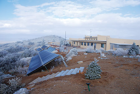
PV modules are rated for output at a set of Standard Test Conditions (STC) that have a sunlight intensity, called irradiance, of 1000 watts per square meter (W/m2), a PV module cell temperature of 25°C (77°F), and an air mass index of 1.5. Mother nature does not provide these standard test conditions day in and day out, hour in and hour out to allow us to easily design the electrical system connected to a PV module. Of course, at night there is no sunlight, in the morning and evening there are lesser amounts of sunlight, and there are cloudy, hazy, rainy, snowy days. So the irradiance varies greatly from hour to hour and day to day. PV modules are typically about 15 to 25% efficient in converting sunlight to electricity. The remaining 80% or so of the sunlight is converted to heat, and that generated heat increases the module temperature. As the module temperature increases, its output decreases. Conversely, on cold winter days with brisk winds, the actual output of the PV module on a sunny day may be greater than its rated output. See photo 1. It is beyond the scope of this article to deal with air mass issues, but some areas of the country have air mass values that are less than 1.5, and this yields a greater output from the PV module.
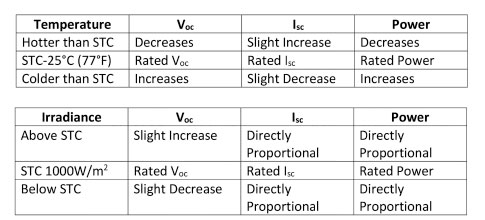
The electrical performance of the PV module is characterized by a series of measurements at Standard Test Conditions (STC). These measurements are open circuit voltage (Voc), short-circuit current (Isc), maximum power voltage (Vmp), maximum power current (Imp), and a set of coefficients that describe how these parameters vary with temperature.
The two tables below show how the outputs of the PV module vary with temperature and irradiance.
From the PV module to the PV system
Because of these environmental/weather variations, the electrical design of a PV system is significantly different from the design of a typical residential 120 V/240 V ac electrical system. The National Electrical Code (NEC) requires that these variations be addressed by the system designer/installer. In most cases, worst-case conditions are used to design the PV electrical system. These worst-case conditions will include the highest possible level of irradiance that the module will ever be exposed to, and the expected coldest temperature that the PV module will ever experience. Additionally, the PV system is designed based on these worst-case conditions being continuous 24/7/365, and no non-continuous loads/sources are considered to exist in the PV electrical system—at least for a pure utility-interactive PV system.
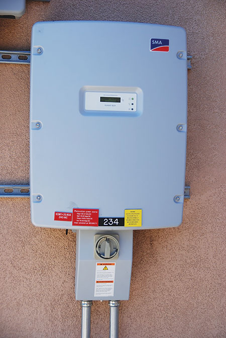
The oldest type of PV system used in utility-interactive systems is the “string” inverter system. The term “string” is used to indicate that a number of PV modules are connected in series to provide a high voltage direct current (dc) output that will work with the inverter. Modules connected in series allow the voltage to increase in the series circuit while the current stays the same at the current of a single PV module. See photo 2. PV designers must select the number of modules to put in series so that in cold weather as the individual module voltage increases, the string voltage does not exceed the maximum voltage input of the inverter. Otherwise, the inverter could be damaged, and other equipment could have rated voltages exceeded. After selecting the number of modules that will be connected in series to make the inverter operate properly, additional strings of modules are put in parallel to increase the overall current and power of the PV array to get the desired power output of the PV system. And, of course, the inverter must have a rated power that is consistent with the maximum dc power output of the PV array under the worst-case conditions of high irradiance and low temperatures.
The instruction manuals for both the PV module and the PV inverter provide necessary safety information on how these devices are to be connected together. The module instructions will provide the STC rated values of voltage and current and also coefficients of voltage current and power that are used to describe how these voltages and currents vary with temperature. The instruction manual for the inverter will provide information on the maximum dc voltage that the inverter can accept and also the maximum recommended current that the dc inputs on the inverter can accept as well as a suggested maximum PV array size.
As a minimum in the permitting process, the PV installer should provide information on the number of modules that are connected in series, the lowest expected operating voltage, and the calculation showing that at this lowest expected temperature, the maximum dc voltage of the string of PV modules does not exceed the maximum rated input voltage of the inverter. Also, the PV installer should provide information from the inverter installation manual showing that the recommended number of module strings in parallel and the subsequent inverter input current is not exceeded. NEC 2014 Sections 690.7, 690.8 and 690.9 deal, to some extent, with these requirements.
Code Requirements for Voltage
In the dc PV circuits, the NEC [110.3(B)] requires that all conductors, all switches, all overcurrent devices, and any other equipment used in these dc circuits have a voltage rating equal to or greater than the expected maximum dc voltage from the PV array under the coldest expected temperatures. Section 690.7 has an Informational Note that gives a source of weather data that can be used to estimate what this lowest expected temperature will be for various locations. An assessment of the historical data from a local weather station might also be used.
Table 690.7 in the NEC is based on crystalline and multicrystalline silicon PV modules only and, in fact, the parameters given are slightly out-of-date based on current module technology. As required by section 690.7 the module temperature coefficients should be used in the calculation of the various voltages where those coefficients are provided in the module instruction manual.
Code Requirements for Current
Although the standard test condition irradiance is 1000 W/m2, actual irradiance in many parts of the country can be considerably higher on clear days. Irradiance values approaching 1250 W/m2 have been measured in many parts of the country for time periods of three hours or more. Therefore, the Code [690.8(A)] requires a 125% factor on the calculated short-circuit currents when sizing conductors, overcurrent devices, switchgear and other devices that might process these currents. It should be noted, that unlike ac circuits where a 200-amp rated circuit may have to deal with thousands of amps of available short-circuit current, these current source dc PV circuits are current limited and in fact the 125% factor on the calculated short-circuit covers the maximum possible available short-circuit current. When the 125% factor is included, the current that is used is called the maximum circuit current and is defined with various requirements in sections 690.8 and 690.9.
This 125% factor should not be confused with a second 125% factor associated with the minimum conductor size and overcurrent device rating for continuous loads as required in 690.8(B) for PV circuits and in Chapter 2 of the Code for various ac circuits.
As noted in 690.8 (4) and (5) some devices like stand-alone inverters and DC-to-DC converters are subjected to slightly different requirements.
Conductor Ampacity Requirements
The requirements for conductor and ampacity in dc PV circuits are addressed by 690.8 (B). The conductors shall be sized to carry the larger of the two following calculations.
- After calculating 125% of the short-circuit current as required by 690.8 (A), the resulting maximum circuit current is to be multiplied by a second 125%. Note that there are no conditions of use involved in this calculation.
- The maximum circuit current shall be adjusted for the conditions of use and other correction factors. Note that there is no second 125% factor involved in this calculation.
If these two calculations are examined more closely, it will be found that in the second calculation, the maximum circuit current is divided by the temperature correction factor and by the conduit fill factor, if any. It can be seen that a maximum circuit current divided by a combined temperature and conduit fill correction factor of 0.8 is equivalent to multiplying the maximum circuit current by 1.25. This inflection point at a combined correction factors of 0.8 tells us that at this point, both calculations will give the same current. If the combined correction factors are larger than 0.8, then the first calculation will dominate and be used to the conductor size. If the combined correction factors are smaller than 0.8, the second calculation will be used to determine the conductor ampacity.
Overcurrent Device Requirements
Overcurrent devices, both fuses and circuit breakers, in the dc PV circuits are typically sized at 125% of the maximum circuit currents. Although there is the standard exception for overcurrent devices in an assembly rated at 100% without the 125% factor, such applications in PV systems are exceedingly rare.
The AHJ should not accept, without question, a statement from the overcurrent device manufacturer that their overcurrent device is certified (listed) for operation at 100% of rating. All commonly used PV overcurrent devices are tested and certified (listed) to hold (not trip or blow) indefinitely at 100% rating, and must open within one hour at 135% of rating. However, when these overcurrent devices are installed in enclosures, their effective rating drops to 80% of the marked value due to thermal considerations and that 125% factor must be applied when sizing these devices unless the exception applies.
New to the 2014 NEC, is the requirement in 690.9(D) that the overcurrent devices in PV source and PV output circuits be certified (listed) as PV overcurrent devices, and those devices as certified will be suitable for dc circuits. Of course, the device voltage and current ratings will have to be suitable for the application.
AC PV Modules and DC-to-DC Converters
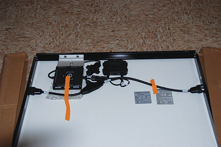
AC PV modules, which have a microinverter attached to the module frame or integrated into the module junction box, avoid the calculations associated with dc PV wiring. See photo 3. The dc wiring in an AC PV module is contained within the module assembly and is evaluated during the certification (listing) process for suitability in terms of types of conductors and current rating (690. 6). The ac output of an AC PV module, normally 120, 240 or 208 VAC, is usually connected to a trunk cable that has been certified (listed) for the application and has been evaluated as being suitable in terms of ampacity, voltage rating, and conductor type. Each trunk cable allows the connection of a number of AC PV modules together in parallel, and this is equivalent to a string of dc PV modules.
Microinverters are similar to AC PV modules in that the dc output cables of the PV module are connected directly to the dc input of the microinverter and no calculations are involved in these dc circuits. The microinverter, like the AC PV module, has an ac output connected to a trunk cable that allows multiple microinverters and their modules to be connected in parallel.
When multiple trunk cables are used to configure sets of AC PV modules or sets of microinverters into an array, the outputs of the individual trunk cables can be combined in an ac combining panel that is essentially an ac load center used in reverse. Because these ac combining panels typically use circuit breakers, they should not be installed where exposed to high temperatures and sunshine due to excessive interior temperatures that may cause the circuit breakers to nuisance trip.
DC-to-DC converters are appearing connected to the dc outputs of PV modules and in some cases integrated into the actual module junction box. These DC-to-DC converters isolate the electrical output of the PV module from the rest of the dc source or output circuits. They also process the electrical output of the module, and the outputs of these DC-to-DC converters have different characteristics than the output of the PV module [690.8(A)(5)]. DC-to-DC converters by different manufacturers operate differently and also have an output unlike the output of the basic PV module. The instruction manual for the converter must be consulted in order to determine the rated output voltage and rated output current of the device. In some cases these output parameters are controlled by a central inverter in a manner that is not defined in the code, again forcing us to use the instructions provided with these listed products [110.3 (B)].
DC Combiners
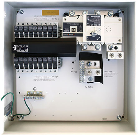
While ac load centers are used to combine the outputs of AC PV modules or microinverters, a similar device known as a dc combiner is used to combine the outputs of strings of PV modules. These devices, normally operating at several hundred volts up to 1500 V, use fuses as overcurrent protection for the individual string conductors connected to the inputs. The fuses must be listed as PV overcurrent devices, and 690.13(C) requires that there be a disconnect on the output of the dc combiner when that combiner is located on the roof of a dwelling or other building. See photo 4. As with ac combiners, the dc combiner should not be located in a high-temperature area or an area exposed to direct sunlight that may result in excessive internal temperatures.
Summary
Sunlight is our most valuable resource and, when properly used, it can provide all of the energy the world needs for future generations. The PV module through the photovoltaic effect is the device that allows us to convert sunlight directly into electricity and that solar-generated electricity has some unique characteristics. The National Electrical Code provides general guidance on how to deal with some of these unique characteristics that are different from the characteristics of typical ac power systems. The complexity of new active electronic devices used in PV systems generally means that the instructions provided with these certified (listed) products be carefully followed to ensure a safe installation
For More Information
The author has retired from the Southwest Technology Development Institute at New Mexico State University but is devoting about 25% of his time to PV activities in order to keep involved in writing these “Perspectives on PV’ articles in the IAEI News and to stay active in the NEC and UL Standards development process. Seven to eight-hour presentations are still available on PV and the Code, and they cover 2008–2014 NEC requirements. He can be reached at e-mail: jwiles@nmsu.edu, phone: 575-646-6105
The Southwest Technology Development Institute web site maintains a PV Systems Inspector/Installer Checklist and all copies of the previous “Perspectives on PV” articles for easy downloading. A color copy of the latest version (1.93) of the 150-page, Photovoltaic Power Systems and the 2005 National Electrical Code: Suggested Practices, written by the author, may be downloaded from this website: https://swtdi.nmsu.edu/codes-standards/