Anyone who has been involved in the electrical field for any length of time has heard the phrase, “path of least resistance,” on many occasions. From the first-year apprentice starting out in the electrical trade to the seasoned veteran of the industry with many years of experience and accomplishments, the phrase is used to describe what path electrical current will take. The phrase is stated with pride “Electricity takes the path of least resistance,” or “Current takes the path of least resistance,” and usually not much thought is given to what is really meant by that statement. This article will review some basic principles of this fundamental element and discuss how this current flow relates to electrical safety.
It is appropriate to review some basic elements of the electrical circuit. First, in order for electrical current to flow, there needs to be a complete circuit or path. Voltage (E) will push current (I) through a resistance (R). These are the basic components of Ohms law. Analogous to electrical current flow is water flowing through a water pipe. The bigger the pipe is, the less the resistance to the flow of the water through the pipe; the smaller the pipe, the more resistance to the flow of water through it. The same holds true for electrical current. Larger electrical conductors (paths) offer lower resistance to current flow. Smaller electrical conductors (paths) offer greater resistance to current flow.
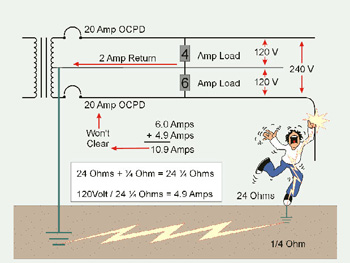
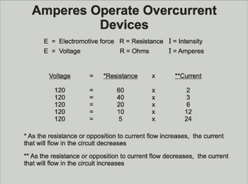
Figure 2. Amperes operate overcurrent devices. Low impedance path means higher current flow.
Where does the current flow? Current will always try to seek out the source, be it normal current or fault current. As for taking the path of least resistance, that is partially correct. Electrical current will take any and all paths available to try to return to its source. If several paths are available for current to flow, it will divide and the resistance of each path will determine how much current will flow on each particular path.
The electrical code in Article 250 mentions several times the term “low impedance path.” As a quick overview, opposition to current flow in a DC circuit is called “resistance.” Total opposition to current flow in an AC circuit is called “impedance,” which is made up of three elements: resistance, capacitance, and inductance. When the term “low impedance path” is used in the Code, it is referring to a path for current to flow on that offers little opposition to current flow whether it is normal current or fault current; the key element is low opposition or impedance.

Figure 3. Current flowing on proper paths provided
Overcurrent devices require current (amperes) flow to operate. The higher the impedance of the path, the lower the current that will flow through the overcurrent device. The lower the impedance of the path, the greater the amount of current that will flow through the overcurrent device. Understanding these basic elements of electrical circuits helps apply some important rules in Article 250 of the NEC.
There are two conductors of a grounded system— the grounded conductor and the equipment grounding conductor—that should be discussed, and a brief story related about each. They are the grounded conductor and the equipment grounding conductor. The grounded conductor (usually a neutral) of a system has been grounded once, at the service or at the source of a separately derived system. The term “grounded” is past tense, which means that the action has already happened. The grounding of the grounded (neutral) conductor of a system is accomplished by a connection to ground through a grounding electrode conductor either at the service or at a separately derived system. The other conductor to look at is the equipment grounding conductor. The word “grounding” is present tense, which means the action is ongoing. In equipment grounding conductors, the action is ongoing through every electrical enclosure all the way to the last outlet on the branch circuit. The equipment grounding conductor puts all metal enclosures at earth potential along the way, and also provides a low impedance path for fault current to flow on if a ground fault should occur in the system. So it is important that the equipment grounding conductor of the circuit make a complete and reliable circuit back to the source. At the source or service is where the grounded (neutral) conductor and the equipment grounding conductor are required to be connected together through a main bonding jumper. The main bonding jumper is defined in the Code as the connection between the grounded conductor and the equipment grounding conductor at the service. In a separately derived system, this connection is made with a bonding jumper installed between the grounded conductor and the equipment grounding conductor. These bonding jumpers complete the fault current circuit back to the source.
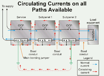
Figure 4
The NEC, in recent cycles, has been revised to continue its migration away from the use of the grounded conductor downstream of the main bonding jumper in a service or downstream of the bonding connection at a separately derived system for grounding equipment. The reasons are elementary as stated earlier. Current, be it normal current or fault current, will take all the paths available to it to try to seek out its source. If the grounded conductor (neutral) and equipment grounding conductors are connected at points downstream of the service or separately derived system connections, such as at sub panels, there will be multiple paths available for current to try to return to the source. This can lead to current flowing on water piping systems, conduit, equipment grounding conductors, and any other electrically conductive path.
In the 1996 NEC the electric range and dryer circuits were required to include an equipment grounding conductor in addition to the insulated grounded conductor. Range and dryer circuits that were existing prior to the adoption of this rule are permitted to continue the use of the grounded or neutral conductor to ground the boxes and frames of the equipment. New installations must maintain this isolation between the grounded conductor and the equipment grounding conductor.
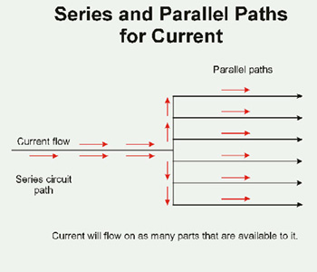
Figure 5. Current will seek its source. It takes any and all paths available. The amount of current flowing in each path is dependant on the impedance of that particular path
In the 1999 NEC, there was a revision to the rules covering the use of the grounded conductor for grounding purposes at a second building or structure. Section 250-32 (b)(1) requires that if an equipment grounding conductor is installed with the feeder supplying the second building or structure, that isolation between the grounded (neutral) conductor is to be maintained. There is an allowance in Section 250-32(b)(2) to utilize the grounded conductor of the feeder for grounding equipment under three specific and very restrictive conditions. First, an equipment grounding conductor is not included with the feeder supplying the building or structure. Second, there are no continuous metallic paths bonded to the grounding system in both buildings. Third, there is no ground-fault protection of equipment installed at the service. If all of these conditions are complied with, the grounded conductor must be used for grounding and be connected to the building or structure disconnecting means. The grounded conductor is also required to be connected to a grounding electrode at the building or structure and installed in accordance with Part C of Article 250. This will serve as the grounding means and as the path for normal current and also the path for fault current to clear overcurrent devices. In Section 250-32(b)(2) the Code mentions a requirement of having no continuous metallic paths bonded to the grounding system in each structure. This is encompassing of all paths, not just wires or conduits. These paths could include items such as metal water pipes, other metal piping, steel members, and paths such as the shielding on a communications cable or a coaxial cable installed between the structures. It is important to remember that current will take all the paths to seek out the source. If this connection were made and there was a ground-fault protection device at the service in accordance with Section 230-95, these connections could desensitize the GFP device and it may not operate properly when called upon to do so in ground-fault conditions because of multiple paths for current.
In summary, it is important that the basic elements of current flow be understood and thought of carefully while applying the rules of the NEC. Section 250-24(a)(5) states that a grounding connection to any grounded circuit conductor on the load side of the service disconnecting means shall not be made, unless otherwise permitted in the article. The FPN gives reference to three situations where this is acceptable, but is restrictive. Sections as reviewed in this writing are for separately derived systems in Section 250-30(b), for separate buildings or structures in Section 250-32, and for grounding equipment under the limitations of Section 250-142. Installers and inspectors should be watchful to ensure there are no neutral to ground connections on the load side of the grounding connections at the service disconnecting means or on the load side of the grounding connections for a separately derived system. In other words, isolate the neutrals and equipment grounding conductor connections. Give current (be it fault current or normal current) the low impedance path anticipated by the requirements of the NEC.