Hazard-based product safety standards are now under development, and this hazard-based approach is likely soon to affect other product/equipment safety standards as well as installation codes.
What is this hazard-based approach? How could it impact safety standards for equipment and installations? Are there relevant applications in electrical safety and practical examples for electric shock and protection?
Hazard-based safety standards can offer clear safety objectives and means to meet them. A hazard-based approach provides us with another way to reduce risk of harm by addressing each hazard. This approach would determine which undesirable effects are to be avoided; the susceptibility to them, their conditions and causes; and appropriate protection against them. A hazard-based standard would identify the objectives of protecting against each specific undesirable effect, and directly relate them to appropriate protection requirements and limits. How does this apply to electrical safety?
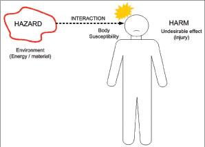
Figure 1. Hazard leads to harm (undesirable effect/injury) if interaction exceeds body susceptibility to that effect.
We’re all concerned with electrical safety; we benefit from it and may contribute to it in one way or another. Safety in the U.S. is addressed in standards such as ANSI C2 National Electrical Safety Code for utility distribution to the building; NFPA 70 NationalElectrical Code(NEC) for premises installation; NFPA 70E Standard for Electrical Safety in the Workplace; and OSHA requirements (29 CFR 1910 Sub-part S) for the workplace; as well as product requirements such as UL/ANSI safety standards covering construction and performance of systems, equipment, devices, components, materials, in addition to safety-critical programmable logic and software.
But what is safety? Safety may be considered as freedom from unacceptable risk of harm.1 The lower the severity and likelihood of harm, the lower the risk and the greater the safety. Safety is relative, not absolute, with a primary objective to reduce risk to an acceptable level.
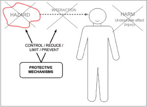
Figure 2. Risk of harm is reduced if protective mechanisms reduce hazard and/or interaction.
The primary objective of electrical safety is to reduce relevant risks to an acceptable level, particularly concerning fire, arc flash and shock hazards. We know electrical energy can be hazardous, even lethal. But many of us may have experienced what we consider electric shock, at levels that were fortunately low. We may know shock by experience, but what is electric shock, what is the harm, how is it caused, and how is it prevented?
In this context of electrical safety, let’s consider electric shock as any undesirable physiological effect due to the flow of current through the body. The harm is the undesirable effect, whether or not a direct injury results. The severity of these effects increases with current levels or duration of time and depends on the susceptibility of body parts in the current pathway. Increasingly higher current causes increasingly severe effects, for example from sensation to involuntary reaction, to strong muscular effects, difficulty in breathing and inability to let go, to ventricular fibrillation and death.
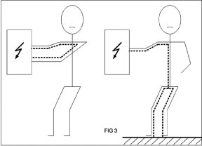
Figure 3. Example body current pathways: hand-to-hand and hand-to-feet (grounded circuit and body).
The susceptibility to these physiological effects is described in IEC Technical Specification 60479.2 This is a basic safety publication that describes the effects of current and the threshold levels at which these effects are likely to begin across the population. In addition, some touch voltage thresholds have been determined that correspond to certain current thresholds, physiological effects and varying body impedance, in a separate proposed draft. This can also provide a better understanding of conventional contact voltage limits (such asNECClass 2) and the underlying conditions that should apply to them, such as skin contact area and moisture, and suitability of startle reaction current levels with regard to contact circumstances.
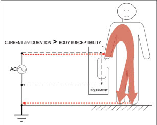
Figure 4. Electrical shock hazard leads to harm (undesirable physiological effect / injury) if body susceptibility to that effect is exceeded. Susceptibility is based on current for a duration.
Based on research data and analysis, these international technical reports include significant US contribution, and are developed by experts in science and engineering disciplines such as physiology, electrical engineering and other relevant fields. Such technical information forms the foundation for this hazard-based approach to codes and standards for safety. It also forms the technical basis for many existing and developing requirements on electric shock and protection, with suitable safety factors between limits and the physiological thresholds of susceptibility.
Hazard-Based Approach: Safety Standards and Codes
A hazard-based approach for safety standards provides a different way to establish a very clear connection between protection requirements and the undesirable effects, such as injury, to be avoided. Likewise, the undesirable effects would be clearly identified and linked to the protective mechanisms in the requirements. Limits to protect against the harm need to be appropriate, based on technically correct analysis and application of data on physiological thresholds of susceptibility, and with safety factors suitable for the level of risk.
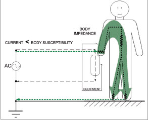
Figure 5. Reducing the risk of electric shock: Body Impedance can limit current below susceptibility to harm (undesirable physiological effects) – but only under the right conditions such as with a low voltage source.
So what is a hazard, how does it cause harm, and how do we protect against it? Simply put, a hazard is something that can cause harm. As an example, a residential Class 1 branch circuit can cause electric shock injury or death to persons that interact with it, directly or by way of wiring, devices or equipment. A hazard-based approach seeks to reduce risk of harm by addressing each hazard. It would first determine the specific harm to be avoided and the susceptibility to it, then analyze the causes of the harm, and then focus on appropriate protection against it.
Determining the harm to be avoided would address each undesirable effect, such as specific injury under set circumstances, and particularly the susceptibility to the harm. Analyzing the causes of harm would cover the mechanisms, factors, conditions and cause-and-effect relationships, and would then identify the source as hazardous. Focusing on appropriate protection would identify and then prioritize protective mechanisms that are effective, reliable and practical.
A hazard-based analysis can provide a clear, straightforward model for an otherwise complex problem. It’s a tool we use to analyze a problem and prioritize its solutions — to solve a problem in the right way. It emphasizes and supports the need to first analyze, then evaluate, test and validate.
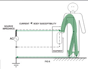
Figure 6. Reducing the risk of electric shock: Source impedance can limit current below susceptibility to harm (undesirable physiological effects) – but only under the right conditions such as with a limited current source.
Hazard-based product safety standards are now being developed by organizations including Underwriters Laboratories and the International Electrotechnical Commission (IEC), for equipment such as information technology, telecommunications and consumer electronics. The objective is to put this theory into practice to meet the safety objective of reducing risk: to address each hazard and its mechanism for harm, in order to address the mechanisms for protection. This type of hazard-based approach is likely soon to affect other product/equipment safety standards as well as installation codes.
A hazard-based approach identifies a hazard such as parts energized by a branch-circuit supply source capable of causing harm upon interaction with persons (electric shock) or property (fire). This interaction results in injury if a person is coupled with this energy at a magnitude, rate and duration that exceeds the threshold of susceptibility, the ability to sustain or withstand it without injury or other undesirable physiological effects. The more severe or likely the injury, the greater the risk.
Protection from harm involves a means to control, reduce, limit or prevent interaction with this hazardous electrical energy source — to reduce the magnitude, rate or duration below the susceptibility threshold. You may have heard the order of priority to reduce this risk expressed as “Eliminate the hazard, guard against the hazard, or warn about the hazard.”
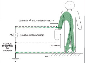
Figure 7. Reducing the risk of electric shock: Source impedance to ground can limit current below susceptibility to harm (undesirable physiological effects) – but only under the right conditions such as with a source that is isolated from ground
Protective mechanisms need to be effective and reliable to mitigate the hazards and reduce the level of risk under all likely conditions of the application throughout the expected life of the product.
All likely conditions — wanted and unwanted — must be anticipated and considered. This includes conditions of normal use and reasonably foreseeable misuse and abuse. Fault conditions are simply unwanted conditions, states or events that may contribute to the harm being considered. Analysis tools such as fault trees are sometimes used to outline the relationships between the factors that contribute to harm — particularly critical paths — and to help design protective mechanisms in the right order of priority. This may highlight the effect of certain external factors that must also be considered. Multiple faults must also be considered. As an example, one fault could precipitate another, or one fault could exist (undetected, indefinitely) and then another fault could occur at the same time.
Hazard-Based Application: Electric Shock— Some Basic Examples
A hazard-based approach can provide a different way to address electric shock harm to a person. Recall that a person interacting with a hazardous energy source is coupled with its energy, resulting in injury if the magnitude, rate and duration exceed certain thresholds. In the case of electric shock, this coupling is caused by contact, and in the form of current that flows for a duration through the impedance of the body. The electrical circuit through the body is completed by two separate contacts: one to the source of current and one to its return. For example a person could make hand-to-hand contact across line–neutral in a circuit, or hand-to-foot contact with a hand on the line-side of a circuit and a foot in contact with ground (concrete floor, water pipe, other grounded parts, etc.), to which the return circuit (neutral) is referenced.
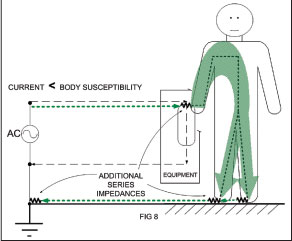
Figure 8. Reducing the risk of electric shock: Additional series impedance can limit current below susceptibility to harm (undesirable physiological effects) – but only under the right conditions such as with insulation / isolation in equipment
Electric shock harm is considered as any undesirable physiological effect due to current that exceeds the threshold of susceptibility for the involved body parts. The harm is based on susceptibility to current and duration, and protection is therefore based on limiting that current or duration. What about voltage? Voltage can be addressed simply by its ability to drive current as limited by impedance, and this is addressed below under subhead Low Voltage Source.
Consideration of Unwanted Conditions
All likely conditions — wanted and unwanted — must be considered. Fault conditions, even multiple conditions, may be unwanted but must be anticipated. As an example, circuits can be miswired, resulting in unintended wiring configurations of branch circuits, receptacles, and connected loads, and leading to unwanted supply source conditions such as no grounding, reversed polarity and open neutral. Open grounding or reversed polarity could exist undetected and long term. Open neutral conditions may not exist undetected as long (indicated by unenergized loads), but consideration is still warranted.
These conditions can increase the risk of electric shock. Leakage current normally flows from the supply source through resistive and capacitive paths returning to accessible conductive parts and ground. But if the grounding connection is open (green wire in the equipment or in the supply), this leakage current is now touch current, available to flow through a person who simply needs to contact accessible metal on the equipment (enclosure) and ground (concrete floor, water pipe, other grounded parts, etc.). In addition, if the neutral connection to the equipment is open, some circuitry normally at neutral (ground) potential will be raised to line potential. As N-G capacitance is typically symmetrical with L-G capacitance, this condition will double the leakage current and further increase the risk of shock.
These conditions therefore form the basis for typical product leakage/touch current testing requirements as in UL/ANSI 101. Products are tested to applicable leakage current limits under these unwanted but anticipated conditions to ensure that the protection against electric shock is effective.
Harm: Susceptibility to Current and Duration
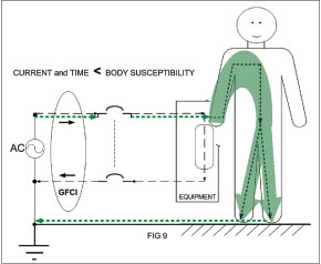
Figure 9. Reducing the risk of electric shock: GFCI can limit current and time below susceptibility to harm (undesirable physiological effects such as inability to let-go or ventricular fibrillation).
For some common Class 1 residential branch circuit applications (240/120 Vac rms, 60 Hz), the following time/current thresholds of physiological susceptibility from IEC TS 60479 provide a frame of reference for the population. The reference is a common current pathway, left hand-to-both feet. Susceptibility may differ with different pathways, as well as factors such as dc, frequency, waveshape and others not included here. Recall that limits in standards and guidelines generally need to be separated by safety factors from the physiological thresholds for injury, with greater risk warranting greater safety factors. Values are given in ac rms, but certain effects involving muscle stimulation may be more closely associated with peak voltages, so the equivalent peak voltages for clean sinusoidal waveforms are also shown. Some examples follow.
The physiological threshold for startle reaction is 0.5 mA AC rms (0.7 mA peak) independent of duration. These effects increase with current and current density over the area of contact. This is also a commonly used leakage / touch current limit in many product standards. If below this level, physiological effects include [possible] perception but usually no [significant] startle reaction.
Note that startle and related effects may not be direct injuries, but could result in injury in certain applications and circumstances simply as a consequence of an unexpected or undesirable physiological effect. This may indirectly cause injury, but injury nonetheless. The harm is the undesirable effect, whether or not an injury is directly caused by the body current.
The physiological threshold for muscular reactions such as immobilization, difficulty in breathing and inability to let-go can be as low as 5 mA AC rms (7 mA peak) dependent on duration. These effects are generally undesirable and could result in injury in certain applications and circumstances. If below this threshold, physiological effects include “[likely] perception and involuntary muscular contractions…but usually no harmful electrical physiological effects.” 2
The physiological threshold for ventricular fibrillation is as low as 35–40 mA AC rms (approx 50 mA peak) dependent on duration, but based on current that may last a few heart cycles (seconds) or more. This threshold current also depends heavily on pathway through the body, and may be higher (such as hand-to-hand) or lower (such as chest-to-hand).
If below this threshold, physiological effects include “strong involuntary muscular contractions, difficulty in breathing, reversible disturbances of heart function, [and] immobilization, [with] effects increasing with current magnitude, but usually no organic damage is to be expected.” 2
Above this threshold, “pathophysiological effects may occur such as cardiac arrest, breathing arrest, and burns or other cellular damage. Probability of ventricular fibrillation [increases] with current magnitude and time.” 2
Note that these are only examples of the many effects of current for branch-circuit applications. Other harmful effects are also possible, depending on factors such as pathway and affected organs and body subsystems.
Hazard-Based Application: Electric Shock Protection—Some Basic Examples
The hazard-based approach provides a different way to address hazards that can cause harm, as well as protective means that can reduce risk of harm, such as electric shock. The safety objective is to avoid certain undesirable physiological effects, and the protection requirements need to address directly the susceptibility to these effects. As electric shock harm is based on susceptibility to current and duration, then protection is based on limiting the current or duration. To protect against a specific effect, the current or duration must be limited below the level that could cause that effect.
Protection: Limiting the Current or the Duration
Current is limited by impedance, but whether we can rely on body impedance, source impedance or some other series circuit impedance depends on the circumstances. Recall that the needed current limitation must be based on the physiological effect to be avoided and the corresponding current threshold (0.5 mA for reaction, 5 mA for let-go, etc.). Note that voltage is simply addressed here by its ability to drive current, but limited by impedance. Current duration (time) can also be limited, such as by specifically designed protective devices. Again, the limitation must be appropriately below the thresholds (time/current) for the specific physiological effects to be avoided. Recall also that protective mechanisms need to be effective and reliable, as well as appropriate for the application. Some examples follow.
Limiting the Current with Body Impedance (Low Voltage Source)
Body impedance consists of internal body resistance that varies with the current pathway, and skin impedance (resistive/capacitive) that varies with skin contact area and moisture condition, frequency and voltage. Note that skin impedance consists of two contacts for entry and exit of current though the body. Body impedance is also ultimately proportional to the current itself as the two skin contact impedances may differ, and vary as a function of the voltage across them.
Let’s look at variation with voltage. Body impedance is high by nature, primarily due to skin impedance. At very low voltages, this impedance remains high enough, on the order of kilohms to adequately impede the flow of current below critical thresholds.
For example under ordinary conditions such as hand contact with equipment and foot contact with ground, NEC Class 2 circuits would not have the potential to reduce our skin impedance and body impedance, and the current able to flow would not be likely to cause effects more severe than reaction. Notable differences include relatively larger contact area, and damaged or wet skin (note lower NEC Class 2 limits for wet contact).
In order for voltage to be low enough to protect against electric shock, the body impedance must be high enough to limit the body current to acceptable levels — under all likely circumstances and conditions of contact. As body impedance decreases as a function of the voltage across the body, the higher the voltage, the lower the body impedance. At lower voltage, the body impedance is higher, but other factors need to be considered including skin contact area and moisture condition.
Limiting the Current with Source Impedance (Current-Limiting Source)
A supply source may have adequate impedance in the normal current-carrying path. A current source has source impedance so much higher than the remaining circuit impedance that different loads (from a normal electrical load, to a body, to a short circuit) do not appreciably change the current. This source impedance would need to be high enough to limit the available body current to acceptable levels, such as below the 0.5 mA AC threshold for reaction.
This source impedance may also exist in the path to ground, such as in a ground-isolated secondary supply. This may provide protection by limiting fault current that may flow in the grounding path through a person contacting the supply and ground.
But in order for such isolation to be an acceptable protective mechanism, it must be effective and reliable in the application. Adequate isolation from ground (protective earth) can be very difficult to maintain for a product due to interaction with users, interconnection with other equipment and contact with other parts and the surrounding environment. Moreover, if this isolation is compromised it is rarely detected or indicated except for special cases involving suitable monitoring and protection circuitry for isolation from ground (for example a line isolation monitor for isolated power systems required in applications such as Health Care Facilities covered by Article 517 of the NEC.
Limiting the Current with Additional Series Impedance
At residential Class 1 branch circuit voltages (240/120 V), the skin impedance is dramatically reduced, and total body impedance approaches only the internal body resistance on the order of 500 Ohms. With this low body impedance and the low source impedance inherent to a branch circuit (voltage source), there is little to impede the current below hazardous levels.
However, there could be other series impedance to limit this current, by intention or by chance. Of course, such protection is a common part of equipment and installations, provided by insulation and isolation, as well as training, work practices and behavior. In many cases suitable personal protective gear such as insulating gloves or insulated tools may be used. Chance impedance could involve increased body resistance due to very small and dry contact areas (fingers, hands), even for a shorter current pathway such as across the same hand. There could also be additional resistance provided by clothing (shoes, etc.) or the environment (dry wood floor, carpet, etc.) depending on the current pathway and circumstances of contact. No one would expect to rely on chance impedances for safety, but this helps explain why some have been fortunate to interact with a hazardous source without the severe consequences that are possible.
Limiting the Current Duration (Time)
In addition, there are other protective mechanisms that limit the current as well as the duration of current, reducing the severity and the likelihood of injury under different conditions. One example is a ground-fault circuit interrupter (GFCI) that detects current differential between the line and neutral conductors. Under high-impedance fault conditions the GFCI shall trip on differential current of nominally 5 mA within approximately 5 seconds (within milliseconds in practice), protecting against muscular reactions such as immobilization, difficulty in breathing and inability to let-go. Under low-impedance ground-fault conditions (short circuit), instantaneous fault current could be much higher, but the GFCI will very rapidly enter the trip mode, required to trip within milliseconds, well below the short-duration threshold for ventricular fibrillation and protecting against it.
Of course there’s much more to all this, but these were just a few basic examples of applying a hazard-based approach to electrical safety and protection against the risk of electric shock.
Summary
This hazard-based approach is now in use and likely to impact safety standards and codes. This basic overview and the electric shock application examples should shed some light on how this hazard-based approach can apply to electrical safety. A hazard-based standard would identify the objectives of protecting against each specific undesirable effect, and directly relate them to protection requirements. Limits to protect against the harm need to be appropriately based on physiological thresholds of susceptibility, with safety factors suitable for the level of risk. This hazard-based approach provides us with another way to address hazards that can cause harm, in order to address protection mechanisms that can reduce the risk of harm.
References
1 ISO/IEC Guide 51, Safety aspects — Guidelines for their inclusion in standards
2 IEC Technical Specification 60479-1, 4th ed., Effects of Current on Human Beings and Livestock – Part 1: General Aspects (by IEC TC64 MT4), a Basic Safety Publication and IEC 60479-2: Effects of current passing through the human body – Part 2: Special aspects.