
Absence of voltage testing is a vital step in the process of verifying and establishing a de-energized state of any electrical system. As detailed in Clause 4.2.5. of NFPA 70E, Standard for Electrical Safety in the Workplace, there is a specific and approved approach to establishing an electrically safe work condition with the following steps:
- determine all possible source of electrical supply;
- interrupt the load current, open the disconnecting device for each possible source;
- verify where possible that all blades of the disconnecting devices are open;
- release or block any stored energy;
- apply a lockout device in accordance with documented and established work procedures; and
- using an adequately rated portable test instrument to test each phase conductor or circuit part to verify it is de-energized. Test each phase conductor or circuit path, both phase-to-phase and phase-to-ground. Before and after each test, determine that the test instrument is operating satisfactorily through verification on any known voltage source.
The key is verification – you need to verify both that the electrical system is de-energized and verify that the test instrument is functioning correctly.
Conducting an absence of voltage test inside an electrical cabinet is not only time-consuming but contains the risk of shock and electrocution from inadvertent contact with electrical circuit paths inside the panel, incorrect application of test instruments, or human error.
To address the issue of risk, NFPA 70E contains an Exception Note whereby the step requiring direct contact with previously energized conductors with an adequately rated test device can be replaced by using an adequately rated permanently mounted test device provided the product in question meets certain requirements such as:
- It is listed and labeled for the purpose of verifying the absence of voltage
- It tests each phase conductor or circuit path both phase-to-phase and phase-to-ground
- The test device is verified as operating satisfactorily on any known voltage source before and after verifying the absence of voltage.
What is an Absence of Voltage Tester?
Listed and labeled for the purpose of verifying the absence of voltage refers to UL 1436 Standard for Safety – Outlet Circuit Testers and Similar Indicating Devices. In this standard in section 5: Glossary, the Absence of Voltage Tester (AVT) is defined as:
“A permanently-mounted test device that is used to verify that a circuit is de-energized prior to opening an electrical enclosure that contains energized electrical conductors or circuit paths.”
An AVT is provided with a test circuit with active indications to verify the absence of phase-to-phase and phase-to-ground voltage.
In Section 12 of UL 1436, there are specific construction and operation clauses related to the AVT product, including the following:
- An AVT shall be provided with the means for the user to initiate the test for the absence of voltage.
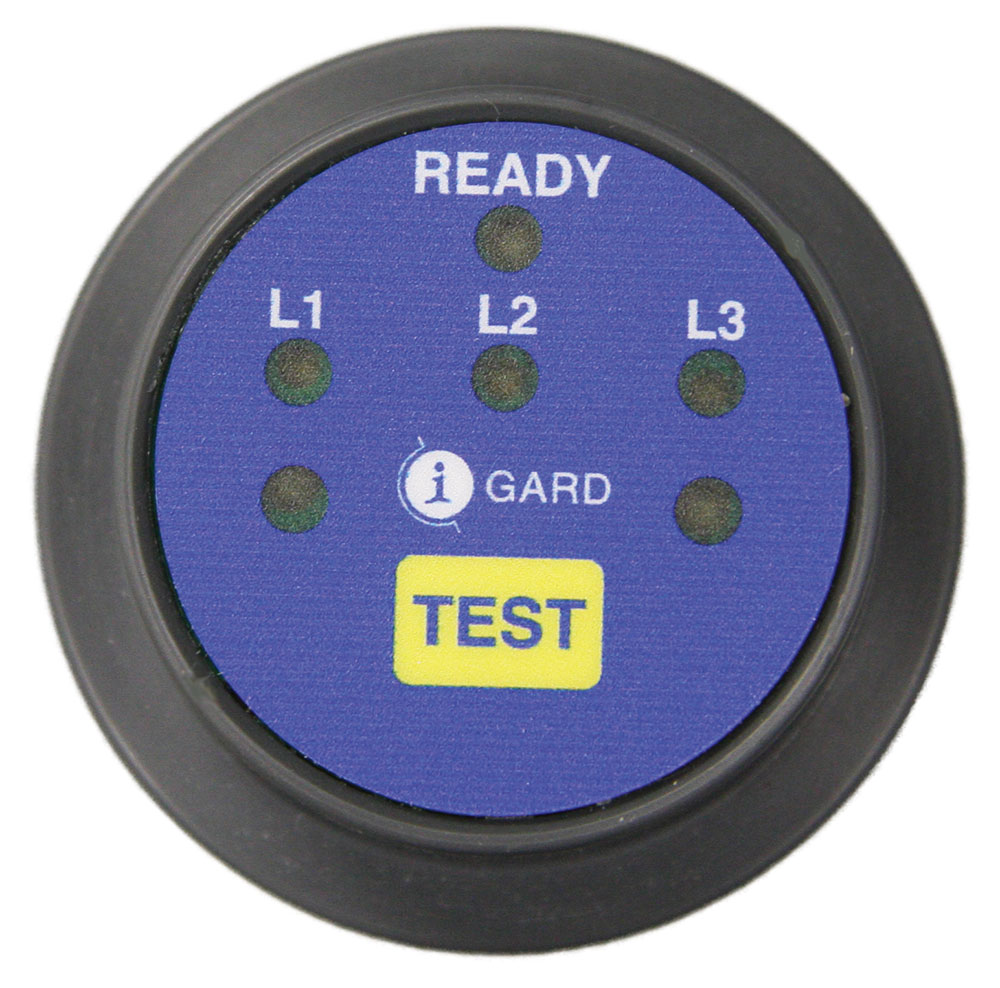
- An AVT shall provide the user with a visual indicator to confirm the absence of voltage after the absence of voltage test has been performed. The visual indication shall be green.
- The AVT shall incorporate a supervisory test circuit to verify that the tester is functioning properly before and after the AVT performs voltage measurements.
- The AVT supervisory circuit has incorporated a secondary power source and shall have no internal failure that would affect performance.
- The AVT visual indicator shall only illuminate green when all phase-to-phase and phase-to-ground voltages measure less than 3VAC or 3VDC.
- The AVT visual indicators shall not illuminate green unless the phase and ground leads are in direct contact with the circuit conductors being tested.
- The AVT visual indicator shall not illuminate green if a phase lead is connected to the ground or the ground lead is connected to a phase conductor.
- The AVT shall comply with the Standard for Functional Safety IEC 61508 and achieve a SIL 3 rating.
Achieving SIL 3 safety rating requires meeting requirements with respect to failure mode effects analysis, meeting requirements with respect to component selection and probability of failure rates, and meeting guidelines with respect to safety concepts and architecture and provides confidence that the AVT product has been designed in such a manner that it will not fail in any critical manner.
Operation and Design of an AVT
A listed and approved Absence of Voltage Tester (AVT) provides a simple means of initiating a test (press the test button). This both reduces the time required to conduct the test from 20 minutes to around 10 seconds and allows the test to be conducted prior to opening an electrical enclosure, thereby reducing the risk of exposure to shock or electrocution hazards.
The AVT provides visual indication of the presence of voltage via 3 phase voltage red lights connected directly to the circuit conductors, thereby indicating that hazardous voltage is present. This functionality is separate from the absence of voltage test and not required by UL 1436 but is available and provides verification of an electrically unsafe condition. This direct connection is part of the integral safety architecture and operation of an absence of voltage tester.
To initiate the absence of voltage test, the user presses the Test button on the display unit. After the Test button is initiated, the test process will not commence until the supervisory circuit has verified that the phase voltage lights are off and the sensor lead connections have been verified.
The continuity check is a critical aspect of verification and is provided through a continuity monitoring loop where two sensors are provided per phase and per ground. If any short or break is detected in any of the leads, then the next test in the sequence will not be initiated. To complete the continuity verification, a signal is injected on one of the sensor leads and is read by the other sensor lead.
Once the above conditions are verified, the following tests are performed in sequence:
- Verify that the energy level on the bus is low enough to perform the test
- Verify that the voltage source is sufficient to perform the test.
- Verify if the phase A RMS voltage is <3V RMS
- Verify if the phase B RMS voltage is <3V RMS
- Verify if the phase C RMS voltage is <3V RMS
- Verify if the phase A connection loop has continuity
- Verify if the phase B connection loop has continuity
- Verify if the phase C connection loop has continuity
- Verify if the phase A DC voltage is <3V RMS
- Verify if the phase B DC voltage is <3V RMS
- Verify if the phase C DC voltage is <3V RMS
- Verify if the phase A connection loop has continuity
- Verify if the phase B connection loop has continuity
- Verify if the phase C connection loop has continuity
- Verify if the phase A RMS voltage is <3V RMS
- Verify if the phase B RMS voltage is <3V RMS
- Verify if the phase C RMS voltage is <3V RMS
- Verify if the phase A connection loop has continuity
- Verify if the phase B connection loop has continuity
- Verify if the phase C connection loop has continuity
- Verify if the phase A DC voltage is <3V RMS
- Verify if the phase B DC voltage is <3V RMS
- Verify if the phase C DC voltage is <3V RMS
These verification tests are performed in sequence, and the next test can only be initiated if the previous verification test has been passed. Only when all verification tests are passed in sequence will all 3 phase green lights illuminate to indicate an absence of voltage.
What About Using Voltage Test Port to Conduct an Absence of Voltage Test?
Voltage test ports allow the user to test for voltage without opening an electrical enclosure (reducing risk and potential exposure to shock or electrocution) and are an excellent tool for troubleshooting and determining safely the value of any voltage that is present.
However, a voltage test portal cannot be used to verify the absence of voltage as per the Note 1 Exception for the following reasons:
- It is not labeled for the purpose of verifying the absence of voltage.
- There is no supervisory circuit to ensure the test portal is functioning properly.
- There is no active indication of the absence of voltage
- There is no continuity check to verify that the leads being tested at the port are in direct
- contact with the circuit conductors being tested.
Reading no voltage at the test port indicates that there is no voltage at the test port, but there is no verification that there is no voltage at the circuit conductors as there is no means of verifying that the voltage test port leads are connected to the circuit conductors. With only one set of leads from the test port to the circuit conductors, a continuity check cannot be undertaken, and therefore connection can not be verified.
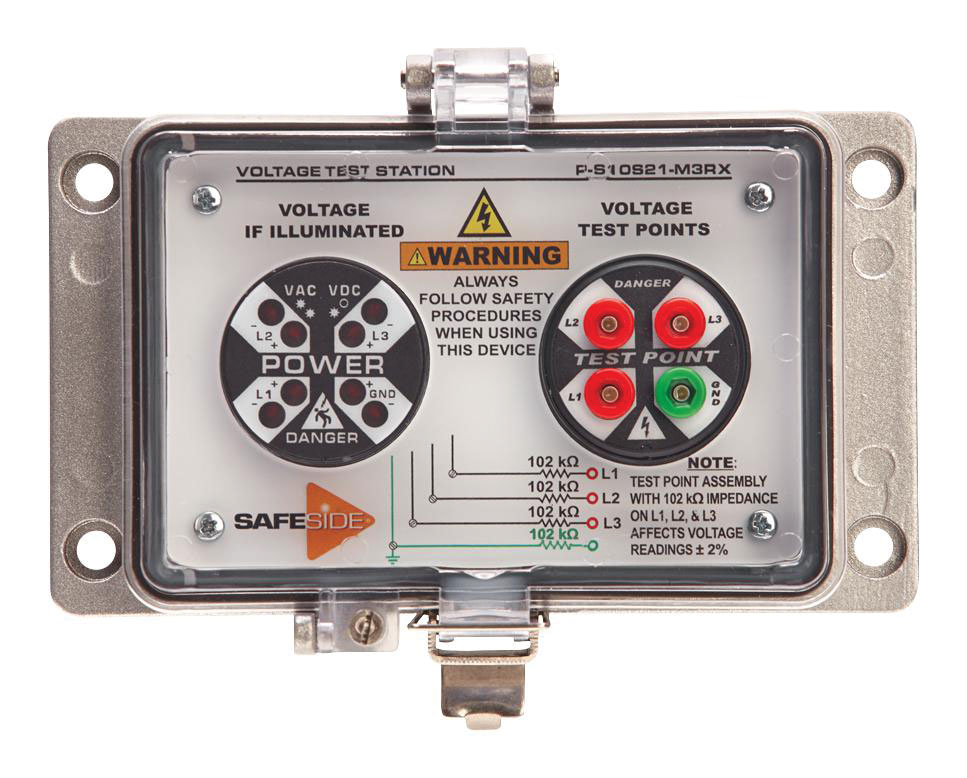
What About Pairing a Voltage Indicator and a Test Portal?
Even if we combine a voltage indicator and a voltage test portal in a single enclosure, both with leads to the energized conductors, this will not suffice to meet the Note 1 Exception for verifying an electrically safe work condition, regardless of whether the work was being performed by a qualified worker or not.
Having two independent connections to the circuit conductors, one set of leads from the voltage indicator and another set of leads from the voltage test station provides redundancy, and while conceptually, if we observe voltage through the indicating lights (confirms the presence of voltage), we then remove the power, observe the lights are no longer illuminated, conduct a voltage test at the test portal using an adequately rated portable test instrument and measure no voltage we cannot verify that there is an absence of voltage for the very same reasons as noted above:
- no supervisory circuit ensuring the test portal is functioning properly,
- no active indication of an absence of voltage,
- no continuity check verify that the leads are connected, all of which are required.
It is clear that if we observe voltage through the indicating lights, observe the lights are no longer illuminated when the power has been interrupted, then measure no voltage at the voltage test port using an adequately rated portable tester that has been checked for functionality, then there is a high probability that there is no voltage on the circuit conductors, but this probability cannot be verified.
When it comes to electrical safety and establishing a safe working environment, a high degree of likelihood simply isn’t enough – the absence of voltage has either been verified, or it hasn’t. Furthermore NFPA 70E 4.1.4. notes that “hazard elimination shall be the first priority in the implementation of safety-related work practices.” Using a combination voltage indicator and voltage test port reduces the probability of a hazard but does not eliminate the hazard given the lack of verification that the leads are connected and the simple fact that the voltage test portal brings full voltage to the electrical enclosure door.
When conducting an Absence of Voltage Test that are two options and only two options – use an adequately rated portable test device and make direct contact with the circuit conductors being tested or use a listed and labeled absence of voltage tester.
NFPA 70E 2021 4.2.5., Exception Notes 1. will be updated to replace the term in permanently mounted test device with a permanently mounted absence of voltage tester to remove any confusion about what product to use and what products are approved for this vital test.