Lightning’s perfect storm for destruction is on the solar field. Solar panels’ large—and often exposed and isolated—location make surge protection critical for it to last its lifespan.
Lightning is an electrical discharge in the atmosphere. When lightning strikes, fires are prone to happen due to the release of energy. Nimbus clouds (rain clouds) have a concentration of electrical charge, and their accumulation creates an ionization of air. The ionization of air that is between the ground and the nimbus clouds creates a discharge from the clouds to the ground. Nimbus clouds cause the biggest surges because they are what generate lightning.
Indirect lightning strikes are destructive. Anecdotal observations about lightning activity is usually a poor indicator of the level of lightning-induced overvoltages in PV arrays1. Indirect lightning strikes can easily damage the sensitive components within PV equipment, which often has a high cost to repair or replace the damaged components and affects the PV system’s reliability1. The overvoltage depends on the setup conditions of each PV system and the wirings.
PV systems are exposed in large open spaces, typically in fields or on the tops of buildings. Charged rain clouds that accumulate over such open fields have the propensity to release the charge in the form of lightning. When this happens, a voltage surge is likely to occur. The more expansive the field is, the more likely destruction is to occur.
Electronic equipment can easily be damaged to the point of catastrophic failure by surges. If a surge occurs when any personnel are present, it will jeopardize their safety as well. Indirect lightning strikes can be fatal if the person is within 60 feet from the point of the lightning strike [2]. When a PV system is located on an industrial site, the business operations and equipment are also at jeopardy. Inverters are expensive, but for industrial applications, an even more expensive failure is the cost of downtime.
When lightning strikes a solar PV system, it causes an induced transient current and voltage within the solar PV system wire loops. These transient currents and voltages will appear at the equipment terminals and likely cause insulation and dielectric failures within the solar PV electrical and electronics components such as the PV panels, the inverter, control and communications equipment2, as well as devices in the building installation3. The array box, the inverter, and the MPPT (maximum power point tracker) device have the highest points of failure.
To prevent high energy from passing through electronics and causing high voltage damage to the PV system, voltage surges must have a path to ground. To do this, all conductive surfaces should be directly grounded and all wiring that enters and exits the system (such as Ethernet cables and ac mains) be coupled to ground through an surge protection device (SPD).
A SPD is needed for each group of the strings within the array box, the recombiner box, as well as the dc disconnect.
Surge Protection Device Classifications
SPDs provide protection against the hazards caused by surges.
UL 1449 [4] defines type 1, type 2, and type 3 SPDs:
- Type 1: One port, permanently connected SPDs, except for watt-hour meter socket enclosures, intended for installation between the secondary of the service transformer and the line side of the service equipment overcurrent device, as well as the load side, including watt-hour meter socket enclosures and molded case SPDs intended to be installed without an external overcurrent protective device. Type 1 SPDs for use in PV systems can be connected between the PV array and the main service disconnect.
- Type 2: Permanently connected SPDs intended for installation on the load side of the service equipment overcurrent device; including SPDs located at the branch panel and molded case SPDs. The Imax value is the maximum single discharge current represented by an 8/20 µs waveform that the SPD can support.
- Type 3: Point of utilization SPDs, installed at a minimum conductor length of 10 meters from the electrical service panel to the point of utilization, for example cord connected, direct plug-in, receptacle type and SPDs installed at the utilization equipment being protected. The distance (10 meters) is exclusive of conductors that are provided with or used to attach SPDs.
Type 1 SPDs protect against direct lightning strikes and are characterized by 10/350 µs current wave. Type 1 SPDs are used in central inverters.
Type 2 SPDs protect against indirect lightning strikes, which are characterized by 8/20 µs waveforms. An 8/20 µs waveform means that the strike has an 8 µs rise time and a duration to one-half peak of 20 µs. Type 2 SPDs prevent the spread of overvoltage into electrical installations and equipment. They also protect against lightning’s electromagnetic effect that propagates a surge within the wire.
A type 2 SPD should be used on each MPPT and within string inverters and array boxes.
The boxes where surges occur are usually damaged from strikes that are indirect. It is not only the type of material and height, but also the shape that affects an object’s ability to attract lightning strikes. If the shape of the box or the material has a propensity to attract lightning strikes, then a type 1 SPD or a lightning rod should be used.
Height, pointed shapes, and isolation are the dominant characteristics that determine where lightning strikes. It is a myth that metal attracts lightning. However, it is important to note that no matter where the PV farm is located, or the shape of any nearby objects, SPDs are essential for every PV system due to their inherent susceptibility to direct and indirect strikes.
Surge Protection Device Selection and Installation for PV Systems
PV systems have unique characteristics, which therefore require the use of SPDs that are specifically designed for PV systems.
PV systems have high dc system voltages up to 1500 volts. Their maximum power point operates at only a few percentiles below the system’s short circuit current.
To determine the proper SPD module for the PV system and its installation, you must know:
- the lightning round flash density;
- the system’s operating temperature;
- the system’s voltage;
- the system’s short circuit current rating;
- the level of waveform that is to be protected against (indirect or direct lightning); and
- the nominal discharge current.
The SPD requirements for an installation that is protected by an external lightning protection system (LPS) depend on the selected class of the LPS and whether the separation distance between the LPS and the PV installation is isolated or non-isolated [4]. IEC 62305-3 details the separation distance requirements for an external LPS.
To have a protective effect, an SPD’s voltage protection level (Up) should be 20 % lower than the dielectric strength of the system’s terminal equipment.
It is important to use an SPD with a short circuit withstand current greater than the short circuit current of the solar array string that the SPD is connected to. The SPD that is provided on the dc output must have a dc MCOV equal to or greater than the maximum photovoltaic system voltage of the panel.
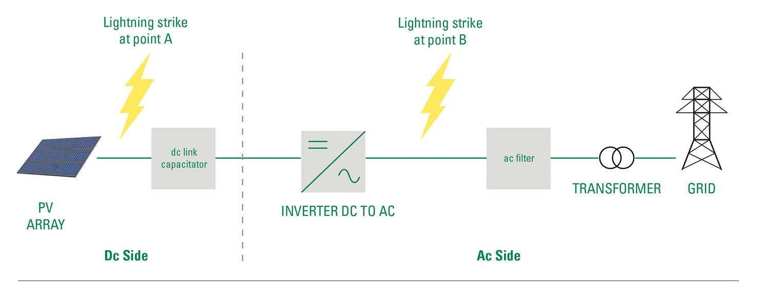
When lightning strikes at point A (see Figure 1), the solar PV panel and the inverter are likely to be damaged. Only the inverter will be damaged if the lightning strikes at point B. However, the inverter is typically the most expensive component within a PV system, which is why it is essential to properly select and install the correct SPD on both the ac and dc lines. The closer the strike is to the inverter, the more damaged the inverter will be.
SPDs For the Dc Side of Photovoltaic Systems
PV sources have very different current and voltage characteristics than traditional dc sources: they have a non-linear characteristic and cause long-term persistence of ignited arcs. Therefore, PV current sources not only require larger PV switches and PV fuses, but also a disconnector for the surge protective device which is adapted to this unique nature and capable of coping with PV currents [1].
SPDs installed on the dc side must always be specifically designed for dc applications. The use of an SPD on the incorrect ac or dc side is hazardous under fault conditions.
When SPDs are used on the dc side, they must also be used on the ac side due to the potential differences.
SPDs For the Ac Side
Surge protection is just as important for the ac side as it is for the dc side. Ensure that the SPD is specifically designed for the ac side.
For optimal protection, the SPD should be sized specifically for the system [5]. The proper selection will guarantee the best protection with the longest lifespan.
On the ac side, multiple inverters can be connected to the same SPD if they share the same grid connection.
Installation
SPDs should always be installed upstream of the devices they are going to protect. NFPA 780 12.4.2.1 says that surge protection shall be provided on the dc output of the solar panel from positive to ground and negative to ground, at the combiner and recombiner box for multiple solar panels, and at the ac output of the inverter [6].
- The proper installation of an SPD relies on three values, which are:
- Maximum continuous operating voltage: The voltage that the SPD will activate.
- Voltage protection level: The equipment’s overvoltage category must be higher than the SPD’s voltage protection level.
- Nominal discharge current: The peak value of waveform (8/20 µs for type 2 SPDs) that the SPD is capable of withstanding after repetitive surges.
Cables
The cables in PV systems are often extended across long distances so that they can reach the grid connection point. However, long cable lengths are never recommended, and PV systems are far from an exception.
This is because the effect of field-based and conducted electrical interference that is caused by lightning discharges increases in relation with increasing cable lengths and conductor loops. When a transient overvoltage occurs, any inductive voltage drop in the connecting cables can weaken the SPD’s protective effect. This is less likely to happen if the cables are routed to be as short as possible.
Surge voltage is a significant contributor to cable failure, and each impulse on a cable will contribute to the deterioration of the cable’s insulation strength.
If a surge is injected into a stand-alone PV system (a system that is far from the power grid), any equipment operations that are powered by solar electricity, such as medical equipment or water supply, may be disrupted [1].
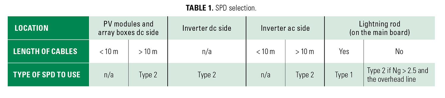
The location and quantity of SPDs to install on the dc side depend on the length of cable between the solar panels and the inverter (see Table 1). If the length is less than 10 meters, then only one SPD is necessary and the SPD should be installed within the same vicinity as the inverter. If the length of the cable is more than 10 meters, then install one SPD within the vicinity of the inverter as well as a second SPD in the box that is close to the solar panel.
Route cables in such a way that avoids large conductor loops. Ac and dc lines and data lines must be routed together with the equipotential bonding conductors along the entire route to ensure that conductor loops are not formed from being routed over several strings or when connecting the inverter to the grid connection [1].
How to Combine SPDs with Inverters
PV farms are comprised of very sensitive equipment that needs expansive protection. Because PV farms create direct current (dc) power, inverters (which are necessary to convert this power from dc to ac) are an essential component to their electrical production. Unfortunately, inverters are not only highly susceptible to lightning strikes but they are incredibly expensive.
NFPA 780, Standard for the Installation of Lightning Protection Systems, in 12.4.2.3 requires additional SPDs at the dc input of the inverter if the system inverter is more than 30 meters from the closest combiner or recombiner box.
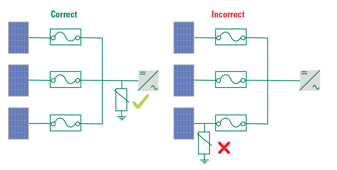
Install the SPD between the fuses and the inverter if there are string protectors (such as fuses, dc breakers or string diodes) [see Figure 2].
To connect an SPD when there is an inverter with an integrated fuse box, ensure that the internal fuses are bypassed and that the external string fuses are connected (see Figure 3). The SPDs must be mounted outside of the inverter and in a NEMA Type- 3R enclosure or higher if it is an outdoor application.
String inverters should be installed as close to the strings as possible. SPD cables that connect to the L+/L- network, and between the SPD’s terminal block and ground busbar, must be less than 2.5 meters. The shorter the connection cables, the more efficient and cost-effective the protection will be.
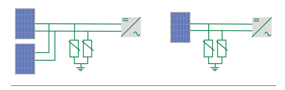
For inverters with only one MPP tracker, combine the string before the inverter and connect them to the SPD at the point of interconnection.
SPD combinations should be planned for each input when the inverter has multiple MPP trackers. An SPD must be used for each input that is fused with a string diode.
Conclusion
To operate photovoltaic equipment without proper surge protection is more than risky business—it is reckless.
For solar systems to be the future of a greener world, they must be protected. The occurrence of lightning is unstoppable and thus, protection is essential.
Photovoltaic systems’ vulnerability to lightning strikes—both direct and indirect—means that they must be built with reliable and properly installed surge protection.
References
- Lightning Protection Guide, DIN EN Standard 62305-3, 2014.
- S. Army Training and Doctrine Command, “Guide for Lightning Protective Measures for Personnel,” U.S. Army, 2002. Accessed: Sept. 13, 2019. [Online]. Available: http://lightningsafety.com/nlsi_ pls/US-Army-Lightning-Protection-Safety-Guide.pdf
- Standard for Surge Protective Devices, UL 1449, 2014.
- Low-voltage surge protective devices – Part 32: Surge protective devices connected to the d.c. side of photovoltaic installations – Selection and application principles, IEC Standard 61643-32, 2017.
- Littelfuse, “Surge Protection in Panel Design,” Littelfuse, Chicago, IL USA, 2019. Accessed on Sept. 18, 2019. [Online]. Available: https://info. littelfuse.com/panel-builders-application-guide
- Standard for the Installation of Lightning Protection Systems, NFPA Standard 780, 2014.
For more information, visit Littelfuse.com/SPD. Reprinted with permission from “Surge Protection for Photovoltaic Systems: Application Guide” by Littelfuse. FORM NO. PF795, Rev: 120119
DEFINITIONS
Definitions
Array: A mechanically integrated assembly of modules or panels with a support structure and foundation, tracker, and other components, as required, to form a dc power-producing unit.
Bonded (Bonding): Connected to establish electrical continuity and conductivity.
Bonding Conductor or Jumper: A reliable conductor to ensure the required electrical conductivity between metal parts required to be electrically connected.
Clamp Voltage: The peak MOV terminal voltage measured with an applied 8/20 µs pulse of rated impulse current.
Direct-Current (dc) Combiner: A device used in the PV source and PV output circuits to combine two or more dc circuit inputs and provide one dc circuit output.
Fault Current: The current that flows when a phase conductor is faulted to another phase or ground.
Ground: The earth.
Grounded (Grounding): Connected (connecting) to ground or to a conductive body that extends the ground connection.
Grounded, Solidly: Connected to ground without inserting any resistor or impedance device.
Isolated (as applied to location): Not readily accessible to persons unless special means for access are used.
Inverter: Equipment that is used to change voltage level or waveform, or both, of electrical energy. Commonly, an inverter is a device that changes dc input to ac output. Inverters may also function as battery chargers that use alternating current from another source and convert it into direct current for charging batteries.
Labeled: Equipment or materials to which has been attached a label, symbol, or other identifying mark of an organization that is acceptable to the authority having jurisdiction and concerned with product evaluation, that maintains periodic inspection of production of labeled equipment or material and by whose labeling the manufacturer indicates compliance with appropriate standards or performance in a specified manner.
Listed: Equipment, materials, or services included in a list published by an organization that is acceptable to the authority having jurisdiction and concerned with evaluation of products or services, that maintains periodic inspection of production of listed equipment or materials or periodic inspection of services and whose listing states that either the equipment, material, or service meets appropriate designated standards or has been tested and found suitable for a specified purpose.
Metal Oxide Varistor (MOV): An electronic component that is commonly used to divert excessive current to the ground and neutral lines.
Module: A complete, environmentally-protected unit consisting of solar cells, optics, and other components, exclusive of tracker, designed to generate dc power when exposed to sunlight.
Nominal Discharge Current (In): The peak value of a current, through the SPD having a current waveshape of 8/20 where the SPD remains functional after 15 surges. The peak value is selected by the manufacturer from a predefined level set by UL. I(n) levels include 3 kA, 5 kA, 10 kA and 20 kA, and may also be limited by the type of SPD under test.
Photovoltaic (PV) System: The total components and subsystem that, in combination, convert solar energy into electric energy for connection to a utilization load.
Short Circuit: Any current more than the rated current of equipment or the ampacity of the conductor. This may result from overload, short circuit, or ground fault. A current flowing outside its normal path, which is caused by a breakdown of insulation or by faulty equipment connections. In a short- circuit, current bypasses the normal load. Current is determined by the system impedance (ac resistance) rather than the load impedance. Short-circuit currents may vary from fractions of an ampere to 200,000 amperes or more. If not removed promptly, large overcurrents associated with a short-circuit can have three profound effects on an electrical system: heating, magnetic stress and arcing.
Short-Circuit Current Rating: The prospective symmetrical fault current at a nominal voltage to which an apparatus or system is able to be connected without sustaining damage exceeding defined acceptance criteria.
Surge Protective Device (SPD): A protective device for limiting transient voltages by diverting or limiting surge current; it also prevents continued flow of follow current while remaining capable of repeating these functions and is designated as follows:
Type 1: Permanently connected SPDs intended for installation between the secondary of the service transformer and the line side of the service disconnect overcurrent device.
Type 2: Permanently connected SPDs intended for installation on the load side of the service disconnect overcurrent device, including SPDs located at the branch panel.
Type 3: Point of utilization SPDs.
Type 4: Component SPDs, including discrete components, as well as assemblies.
Ungrounded: Not connected to ground or to a conductive body that extends the ground connection.
Voltage: The greatest root-mean-square difference of potential between any two conductors of the circuit concerned.
Voltage to Ground: For grounded circuits, the voltage between the given conductor and that point or conductor of the circuit that is grounded; for ungrounded circuits, the greatest voltage between the given conductor and any other conductor of the circuit.
Voltage, Nominal: A nominal value assigned to a circuit or system for the purpose of conveniently designating its voltage class (such as 120/240 volts, 480/277 volts, 600 volts).
Voltage Protection Rating (VPR): A rating per UL 1449 4th Edition, signifying the rounded-up average measured limiting voltage of a surge protection device when the device is subjected to the surge produced by a 6 kV, 3 kA 8/20 µs combination waveform generator.
Voltage Protection Level (Up): Maximum voltage that is to be expected at the SPD terminal when it is subjected to the SPD’s nominal discharge current (In).
Wavelength: The distance between adjacent peaks or troughs of a wave.
Codes and Standards
Codes
National Electrical Code
NEC ARTICLE 285 Surge Protection
NEC ARTICLE 690 Solar Photovoltaic (PV) Systems
International Electrical Code
IEC 61643-11 Low-voltage surge protective devices
– Part 11: Surge protective devices connected to low-voltage power systems. Requirements and test methods
IEC 61643-12 Low-voltage surge protective devices
– Part 12: Surge protective devices connected to low- voltage power distribution systems – Selection and application principles
IEC 62305-3 Protection Against Lightning – Part 3: Physical Damage to Structures and Life Hazard
IEC 62305-4 Protection Against Lightning – Part 4: Electrical and Electronic Systems Within Structures
Standards
UL and North American Standards
C22.2 NO. 269.2-17 Surge Protective Devices – Type 2 – Permanently Connected
NFPA 780 Standard for the Installation of Lightning Protection Systems
UL 96A Standard for Safety, Installation Requirements for Lightning Protection Systems
UL 1449 Standard for Surge Protective Devices
UL 1741 Standard for Inverters, Converters, Controllers and Interconnection System Equipment for Use With Distributed Energy Resources
International
AS/NZS 5033 Installation and safety requirements for photovoltaic (PV) arrays
CEI EN 50539-11 Low-Voltage Surge Protective Devices – Part 11: Requirements and Tests for SPDs in Photovoltaic Applications
IEEE C62.34 Test Methods and Performance of Low-Voltage (1000 V Rms or Less) Surge Protective Devices Used on Secondary Distribution Systems (Between the Transformer Low-Voltage Terminals and the Line Side of the Service Equipment)
IEEE C62.41.1 Guide on the Surge Environment in Low-Voltage (1000 V and Less) Ac Power Circuits
IEEE C62.41.2 Recommended Practice on Characterization of Surges in Low-Voltage (1000 V and Less) Ac Power Circuits
IEEE C62.72 IEEE Guide for the Application of Surge Protective Devices for Use on the Load Side of Service Equipment in Low-Voltage (1000 V or Less, 50 Hz or 60 Hz) Ac Power Circuits
LPI 175 Standard for the Design – Installation – Inspection of Lightning Protection Systems
AS/NZS 1768 Lightning protection