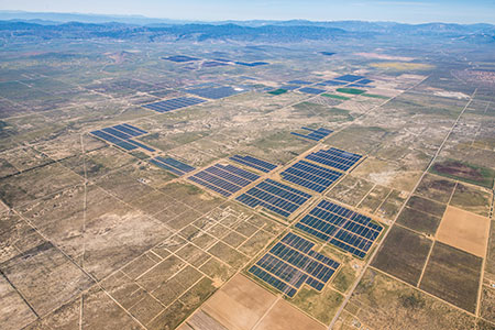
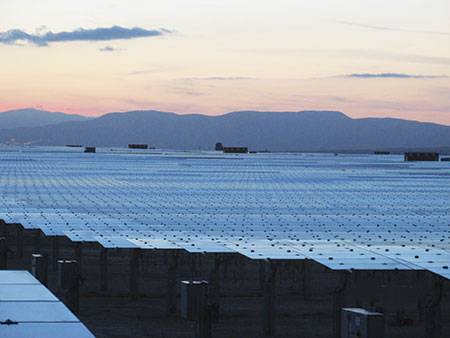
A few years back while at an IAEI sanctioned event, I remember talking with a senior plan-checker about large-scale PV systems versus residential PV systems. I attempted to describe the major differences, but was met with skepticism and a general statement was made that large-scale PV systems “are no different than residential PV systems.” I would agree that the general concept of collecting and capturing photons, converting the energy from DC to AC, and sending the energy on to the grid is similar. However, the system size is sometimes over 4 square miles, and the equipment components, medium/high voltage equipment, and the substations used for collection and distribution are very different and mimic large industrial power plants. At one project, we were three-quarters through completion of a 230-MW plant, and we added up the distances for all the aboveground and underground 1000-volt, 34.5-kV and 230-kV collection/distribution; it equaled the distance from Lancaster, California to Vancouver, British Columbia. It then dawned on me why I had worn out two pairs of boots on this project.
So now that you understand a little more of the size and scope of these projects, it is extremely important to have a well-organized, seasoned, knowledgeable inspection team. Your team will need to consist of more than one electrical inspector. You will have structural steel, high-strength (HS) bolting, high-strength concrete, post-installed/cast-in-place anchors (epoxy anchors), drilled piers, structural welding, welding qualifications, deeply driven piles, fabricated parts with suspect welds, third-party testing of the medium/high-voltage equipment, and, possibly, NRTL Field Evaluations for unlisted electrical components. An extremely knowledgeable combination inspection staff with a team of well-seasoned (craft) special inspectors is the best team for these multi-megawatt projects. If your jurisdiction has special requirements for approved fabricators of concrete and steel, your staff may go beyond your local borders to other parts of the country to review and approve different fabricated components for torque tubs, tracker-motor brackets, large utility vaults and/or equipment skids made of structural steel and/or high-strength concrete.
The Array
Large scale PV usually consists of 1000-volt DC equipment. However, I have heard of 1500-volt systems currently being installed across the U.S. Section 690.4(D) requires the modules to be listed/certified by an NRTL for 1000 volts DC. The calculations at the string level are basically the same as the more common 600-volt residential and commercial systems, but with large PV systems, you are just using larger numbers. The support system, if used as the bonding path for the system, would be listed/certified to UL 2703 (Standard for Mounting Systems, Mounting Devices, Clamping/Retention Devices, and Ground Lugs for Use with Flat-Plate Photovoltaic Modules and Panels) and would be limited to 1000 volts as referenced in the scope.
1.2 “These requirements cover rack mounting systems and clamping devices intended for use with photovoltaic module systems with a maximum system voltage of 1000 V.”
If your system also incorporates a tracking system, single axis or dual axis, UL Standard 3703 would be an appropriate listing, and if additional features such as a battery system were employed in the design, the manufacturer should reference and utilize the appropriate UL Standards for that component.
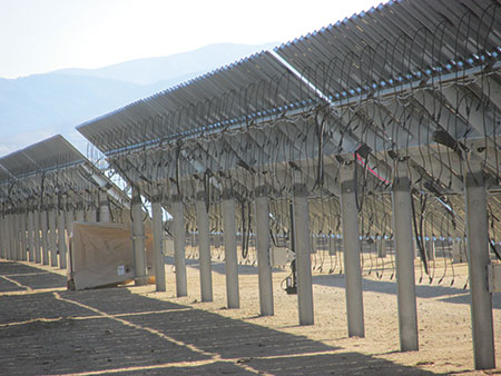
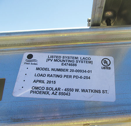
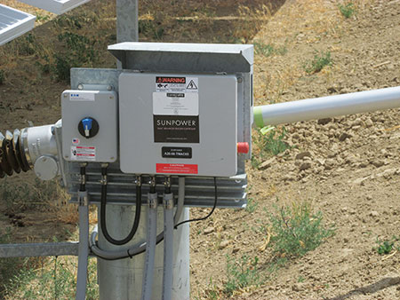
The next concern is all of the string wirings within the array (see photo 1). Typically, the cabling is PV wire 2000-volt rated and approved for direct burial and sunlight-resistant resistance. Some installers will cable to the combiners underground while others will install cable tray systems currently allowed by the 2014 NEC. Don’t forget to apply the requirements in Article 392 (Cable Trays). Proper cable support for the exposed cabling is important for these large systems and can involve hundreds of thousands of cable ties. If you are asking for a listed/certified product, the appropriate UL Standard is 62275 (Cable Management Systems – Cable Ties for Electrical Installations). Additionally, with some PV module technology, like thin-film, you will have more single strings associated with the installation and the contractor will parallel these single strings before terminating at the DC combiners. These DC harnesses will be listed to UL 9703 (Distributed Generation Wiring Harnesses) and have in-line fuses, all of which are sealed, listed/certified to UL 2579 (see photo 3). Also, if the installer is fabricating his own jumpers and installing “Recognized Components,” you will need to decide whether to allow the contractor to proceed on his own (no oversight for this unlisted component) or have him provide some verification by an independent third-party field evaluation. With all of the thousands of connections and the velocity of the project, I recommend oversight at the beginning by a qualified NRTL following the manufacturer’s installation instructions with all the appropriate tools. This will eliminate most of the common mistakes encountered, including the use of incorrect tools or improper techniques, and provides the contractor with a little education in the importance of properly terminating 1000-volt connectors.
The DC Combiner
Article 690.4 tells us to look for listed/certified DC combiners and, in large PV systems, most will need to meet the 1000-volt requirement. The appropriate UL Standard for DC combiners is UL 1741, and pay special attention to the installation instructions. The instructions should give details of how many strings and/or inputs are allowed at what current level, as well as the torque values for conductors, conduit and/or connector penetration locations. The fuses need to be properly sized and the calculations verified at plan check. The main things to look for on the label are the following:
- listing mark;
- model number;
- input rating — VDC and ADC short-circuit current (Isc);
- enclosure type rating;
- operating temperature; and,
- date of manufacture.
If, for example, the operating temperature is absent from the label, then the component is only rated for 25⁰C (77⁰F) according to the 1741 Standard. Additionally, don’t forget to check Table 110.34(A) for the “Minimum Depth of Clear Working Space at Equipment.” This is really important for contractors working on large scale PV projects because if this is an issue in one row of modules, it usually means it is an issue in all of the rows of modules. The author has had several occasions where a cable tray or the next row of modules impeded into the work space, which can be overwhelming to the contractor given the duplication of the violation in the field. Try to catch this at plan review.
The 1000-volt Inverter
Just as with the DC combiners, Article 690.4 tells us to look for listed/certified inverters. The appropriate UL Standard is 1741 and inspectors must again pay special attention to the installation instructions. The instructions give minimum clearances for ventilation/access doors, AC/DC conduit entry zones, communication conduits, and torque values for conductors. Most have the overcurrent protection incorporated into the unit. However, older models will not and will require additional plan review and inspection for compliance. Per the UL 1741 Standard, the main things to look for on a label are:
- module number;
- enclosure type rating;
- ambient temperature range;
- DC Input (MPPT Range, Maximum Voltage, Maximum Current Operational, Maximum Current Short Circuit);
- AC Output (Nominal Voltage, Operating Voltage Range, Nominal Frequency, Operating Frequency Range, Maximum Power at Nominal Voltage, Power Factor); and
- date of manufacture.
Again, don’t forget to check Table 110.34(A) for the “Minimum Depth of Clear Working Space at Equipment.” The author has had several occasions where the minimums were not achieved because the equipment was installed with the doors facing each other, which created a condition with live parts on both sides. Because of this, a minimum of five feet (under condition 3) was required. Again, better to catch this early in the plan review so that this mistake is not duplicated repeatedly in the project, therefore causing the contractor to have to institute numerous fixes. One important thing to be aware of during plan review is that the cut sheets supplied for plan review may not provide details of the large ventilation hoods that may be on the front and rear of these units. This may result in the hoods impending into the work space and thus being out of compliance with the code.
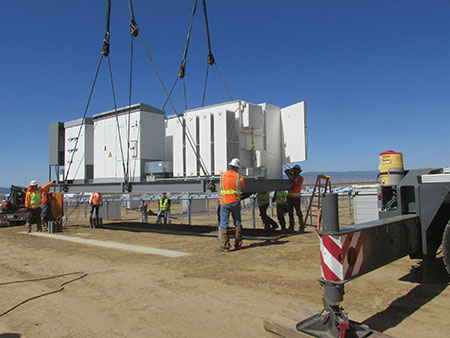
The Medium Voltage Transformers
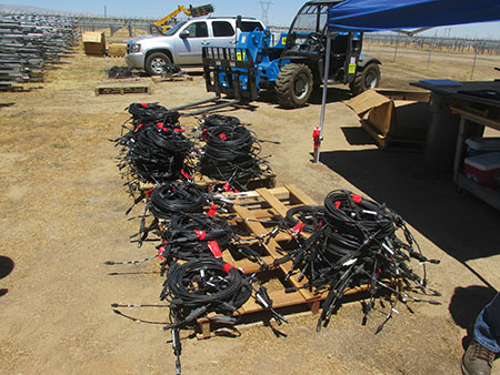
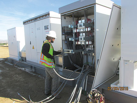
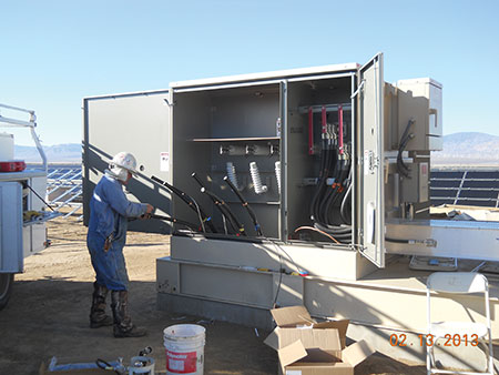
Usually, right next to these 1.5 to 2 megawatt inverters is a step-up transformer. The most common voltage encountered on these large PV systems is 380-V three-phase to 34.5-kV. The vast majority of transformers seen in the field are properly listed. There are times when the inspector will find transformers with no listing and, therefore, a field evaluation may be required. Again, pay special attention to the manufacturer installation recommendations. The conductors always enter through the bottom of the enclosure and the transformer may or may not be installed on a vault. The low side of the transformer will have bolted terminations with multiple locations for parallel terminations. Always ask for the manufacturer’s recommendations for stacking order of the nuts, bolts, washers, lock washers, and/or Belleville washers. Usually, grade 5 nuts and bolts are required (refer to UL Standard 891 Annex G-3.3.3 as a base standard for bolted connections), but the engineer of record (EOR) may specify alternatives, such as stainless steel hardware. Proper bolt torque is critical on both the high side (if dead break connectors are used or open bus is used), and low side of the transformer. Now here is where the first challenge is usually encountered. The cable terminations used for the medium-voltage (and high-voltage) equipment are not listed/certified and, depending on your comfort level with the contractor, they may require further evaluation by a qualified third-party (see photo 7).
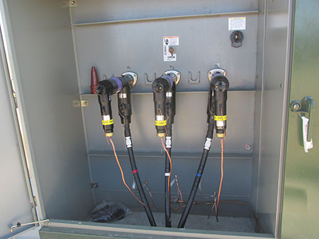
Some of the unlisted items you will see include dead-break BOL-T connectors, load-break BOL-T connectors, surge arresters, underground splice kits, concentric neutral ground kits, cold shrink kits and maybe 8 inch PVC conduit with custom large radius sweeps. This is just a partial list of the challenges you will run into with unlisted equipment. The author has identified, with the assistance of UL, all of the appropriate UL/IEEE Standards required to achieve a proper, field-evaluated component. We have encountered some failures and some quality issues with these components during our evaluations; however, remember, there are currently no listed products for the US market. Make sure your cable splicer is qualified and monitor his/her progress. If you are unfamiliar with medium/high voltage terminations, ask questions, read the documentation supplied with the components, and contact the manufacturer for assistance. Incorrectly installed medium/high voltage cables can be extremely dangerous and usually lead to violent unscheduled events. The author has had personal experience with a 34.5 kV arch-flash blast at a collection switch due to loose terminations and dissimilar materials used for the termination. At another location, the doors of a 34.5 kV transformer were blown off and landed 100 ft. away, partially destroying an array. I no longer allow installers to tension medium/high voltage bolts without an inspector present to check the tools and components used.
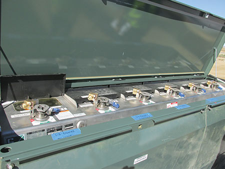
The Collection Switch
What is usually called either the “collection switch,” or the “way switch,” is formally named the Medium Voltage Distribution Switch. It is usually rated at 38 kV. These switches are used as load break disconnects equipped with kirk key interlocks to assist with proper lockout/tagout. This is usually the last switch outside of the substation. The switch mechanisms and bus are totally sealed in a welded tank with SF6 (sulphur hexafluoride) insulated gas. These can be pad-mounted or installed on large vaults, depending on the preference, with 1 to 6 switches. These switches are not listed/certified to include the medium/high-voltage dead-break/load-break connectors (discussed earlier) and may require further evaluation by a qualified third party. Additionally, sometimes this is where some additional control equipment and wiring may be incorporated into the equipment (for instance, fiber optic cables from the substation control building, CTs from the substation, and additional step-down transformers for various controls). The appropriate standards used to evaluate this equipment are IEEE C37.20.3 and IEEE C37.74. A qualified evaluator may be required to evaluate 100% of the production tests at the manufacturer location before shipment to the site to ensure safe operation by the operator.
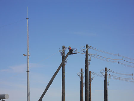
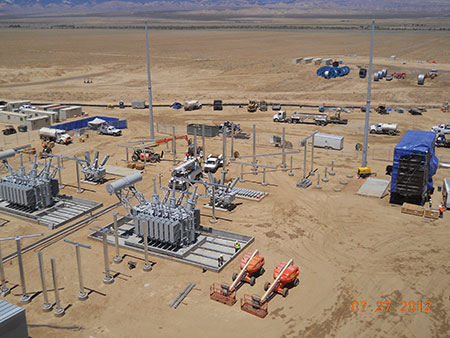
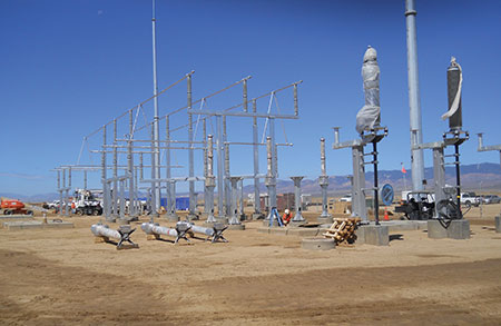
The Substation
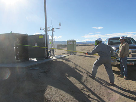
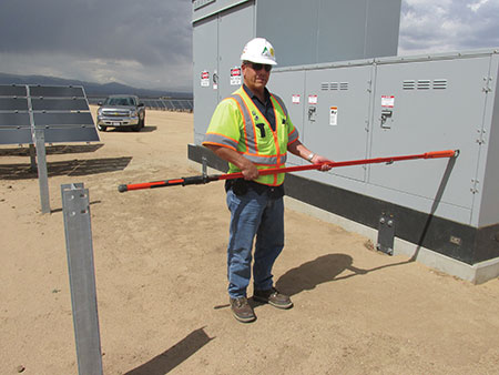
The substation is the ultimate challenge for the electrical geek. These PV sites usually have an onsite substation 69 kV or 230 kV or a feeder that travels several miles to an existing privately owned substation for distribution to the utility. This is where we step-up the voltage from 34.5 to 69 kV or 230 kV or higher. The site may have two or more substations with individual feeders heading to the main utility substation. Typically, the equipment is not going to be listed/certified by any NRTL; however, a qualified NRTL with experienced electrical engineers in the field can properly evaluate and test these components to all the appropriate UL/IEEE Standards. On one recent project with a 69 kV substation, 25 different field evaluations had to take place for unlisted electrical components. The only components that were properly listed/certified were the 35 kV feeder cables, main transformer and some of the equipment in the control building. The air switches, gas breakers, surge arresters, ground switches, capacitors, dead-break connectors, stress cone terminations, VTs, CTs, and control building (and possibly other components) will all require some level of inspection depending on your comfort level and inspection experience. Personally, this is where I camp out with my inspection team. The substation is the brain of the PV plant and has hundreds of bolted connections for the equipment and support structure. During construction, all paper work is gathered and components checked and matched to the engineered design. You may have welded connectors on your medium voltage jumpers (69 kV or 230 kV) that may require verification before and after fabrication. It is recommended to always require review of the welding procedures to ensure the welder is utilizing compatible materials and following the D1.1 (Welding Code) for these fabricated cables. Some substations will utilize schedule 40 aluminum conductor at various sizes as the feeders. Again, you may require some level of verification to insure it’s installed properly and complies with the project specifications. Additionally, the inspector will need to verify the underground electrical and engineered ground mat installed under the substation rock. When complete, the EOR will specify the type and depth of rock to be placed within the substation to mitigate any step and touch potential. Article 110.31 mandates a 7-foot fence to surround the substation, however OSHA 1926.403(j)(2) requires an 8-foot fence or wall. It is recommended to default to the OSHA requirement (8 ft.), which is the same as the local utilities. Sometimes the minimum requirements of Table 110.34(A) are not adequate or easily recognizable by the engineering design team regarding the equipment (tool space) needed to perform lock-out tag-out tryout (see photos 9A & B). The normal hot stick/shotgun used at these sites is almost 8 feet long, and the minimum distance of 5 to 6 feet may not be adequate to allow the qualified person to perform his/or her work in a safe workmanlike manner. Now that I’ve put you all to sleep and you’re rubbing your forehead because it just hit the desk, let’s switch gears and review some of the International Building Code requirements that will need to be reviewed and applied at your site.
IBC Requirements
The most important section of the IBC for inspectors working on these large scale projects is Chapter 17. This section of the building code details the type of construction and materials required to be inspected/verified by the special inspector (SI) and the frequency required for this task. For certain situations, the SI qualifications required for performing the inspection are also outlined. The Tables in Chapter 17 include:
- 1705.2.2 for steel
- 1705.3 for concrete
- 1705.6 for soils
- 1705.7 for deeply driven foundations (piles)
- 1705.8 cast in place foundations (drilled piers)
- All of these requirements are applicable to these large scale PV projects based on the wind load design.
Steel
One detail that the SI will verify is the mill-certifications item or #1 in Table 1705.2.2. This documentation should be traceable by heat numbers or lot numbers on the steel correlating to the place of origin listed on the shipping documentation. If welding is occurring on your project, then item #2 in Table 1705.2.2 will apply, and welding inspector qualifications are detailed in Section 1704.2.2.1. Additionally, the inspector will check the welding procedures (recipe) to ensure compliance with the AWS D1.1 (Structural Welding Code). There are other duties of the SI, such as reviewing welding qualifications and matching/testing machines to individual welders.
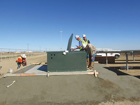
Concrete
The basic requirement to remember about concrete is that any concrete with a compressive strength over 2500 pounds per square inch requires SI review, as detailed in Table 1705.3. The SI will want to see a mix design; and when the truck arrives, will check batch time, water content, outside temperature, and placement. The SI will take sampling for air content, slump, and test cylinders to conduct break tests at determined intervals. Additionally, this section requires verification of the reinforcing steel used with the concrete. And don’t forget about attaching the aforementioned equipment to the pads/vaults. The anchors are used to secure the various steel structures in the substation, and are either post installed or cast in place. The large equipment in the field will need to be verified by an SI. As an example, see the ICC-ESR-1917 report for HILTI KWIK Bolt that requires SI. If you’re an electrician, you have installed lots of these anchors. However, you might be surprised to learn of the high number of deficiencies that the SI will identify during the installation.
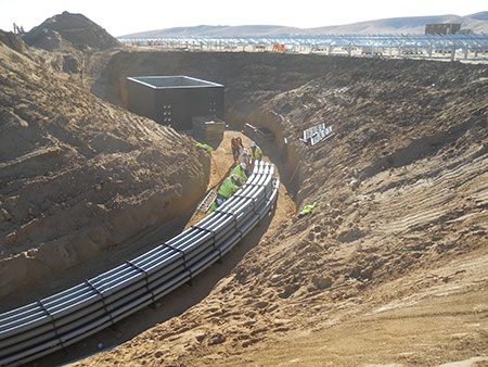
Soils
Table 1705.6 identifies the actions of the soils SI and the two main issues that occur most often are over excavation and replacement of compacted fill. This occurs at the substation and equipment pads/vaults and may extend up to 5 feet beyond the equipment to ensure a good foundation for the critical components. Additionally, all backfilled electrical trenches will have compaction inspections with (the most common device) a calibrated Nuclear Gauge for Density and Moisture Soil Testing. The requirements are usually buried in the geotechnical report and will specify a lift (amount of compacted soil in inches) and the dry density (compaction) required.
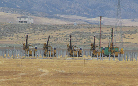
Driven Piles (Driven Deep Foundations)
Table 1705.7 is used for the driven piles associated with some of these systems. If the system is a ballasted system, then this section would not apply. These piles are driven into the ground vertically by a specially designed machine at a rate of several hundred a day, depending on the velocity of the project. If the system has deeper and/or larger diameter piles located around the exterior of the array to satisfy wind loads, the depth and width of the piles will need to be verified for placement. Some designed systems may have 10 different size and depth requirements so special attention to the placement and location of the piles is very important for wind loading requirements. Additionally, before placement/installation of the driven pile, the inspector should refer to the documentation provided during delivery (i.e., conduct a steel inspection) to ensure only qualified materials are used. Observing the driven pile installation is a continuous SI inspection.
Cast in Place Deep Foundations (drilled piers)
This activity usually occurs in the substation and some tracker systems. Table 1705.8 requires the inspector to be present for the entire operation in order to continuously inspect the proceedings, observe any cave-in, and identify soil conditions during the drilling activity. The SI will need to verify the reinforcement cages are properly placed after drilling, verify rebar configuration to the approved drawings, and confirm the placement of concrete, which is another continuous SI activity.
High-Strength Bolting
Chapter 22 (Steel) of the IBC Section 2204.2 states: “Special inspection of the installation of high-strength bolts shall be provided where required by section 1705.” Section 1705.2.1 “Structural Steel” SI for the structural steel shall be in accordance with the quality assurance inspection requirements of AISC 360 (American Institute of Steel Construction). The AISC will give direction to proper storage of high strength fasteners, calibration of tools used for tensioning bolts, different methods of tensioning fasteners, including, but not limited to turn-of-the-nut method, snug-tight, pretension (torque wrench), torque control for twist-off bolts (tension control gun), and air/hydraulic methods that use calibrated tools to apply the required force. The AISC also provides information on how to properly identify markings on the nuts, bolts, washers and will tell you when lubricated assemblies are required. This is just a very limited list of the requirements that the AISC provides. There are many more. I won’t bore you with the micro details of all of the requirements (I just heard a deep sigh of relief), but please remember these large PV systems will have some high-strength bolts used to satisfy the wind loads encountered in places like the high desert or elevated locations with high wind velocities. A thorough review by your structural department will ensure a safe installation.
I did not address the Fire Code in this article. However, you may want your Fire Marshall to review access roads to make certain they are wide enough for the large turning radiuses required for the fire trucks. The Fire Marshal will also review for proper compaction/surface materials on the dirt access roads to confirm they are appropriate to properly support fire vehicles/trucks that may need to drive on these surfaces during an emergency. The equipment protection for vehicular traffic will also be reviewed, along with the visible warning signage required around the perimeter fencing in order to warn the general public of the dangerous voltages just beyond the fence.
As you can see, these large PV systems have many aspects to consider. I have only scratched the surface to spark interest and stimulate your thinking regarding the complexity of these systems and other module codes required for compliance. These systems, if properly installed, inspected, and commissioned, will operate safely and efficiently for many years, with limited maintenance and/or unscheduled power events.
If this article has generated any additional questions and/or comments, please contact the author by phone 619-318-7310 or by email at shinspections.inc@cox.net