
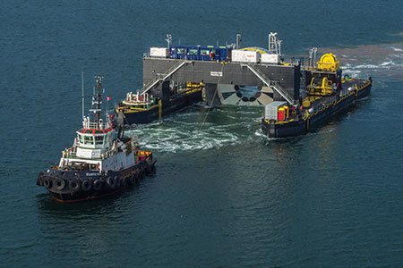
Hydrokinetic turbine generation process uses flowing water in the form of ocean tidal energy, river in-stream energy, or ocean current energy to generate electricity. This article focuses on tidal energy generation process. Until now, activity in a process of hydrokinetic generation has been relatively small. On November 7, 2016, a 2 mW hydrokinetic turbine generator (turbine), the largest of its kind in the world, was deployed in the Bay of Fundy.
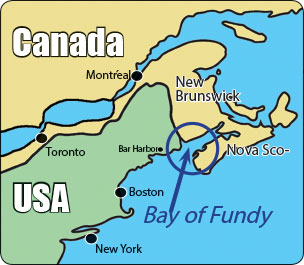
The Bay of Fundy is located in Canada, between Nova Scotia (NS) and New Brunswick (NB), and it has the highest tides in the world. The tremendous energy potential makes this site an ideal location for an instream tidal energy project like Cape Sharp Tidal.
Cape Sharp Tidal is a joint venture between Emera Inc. and OpenHydro (a DCNS company). The first project phase involves two 2 mW turbines that will provide power to over 1,000 homes in Nova Scotia. Subject to regulatory approval and successful monitoring programs, this project has the potential to be expanded up to a 300 mW output of generation. Unlike other intermittent sources of renewable energy, tidal energy is predictable.
The turbine subsea bases and specially-built deployment, maintenance and recovery barge were all designed by Irish marine tech firm, OpenHydro and manufactured in Pictou, Nova Scotia.
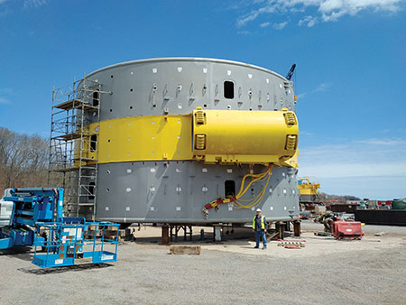
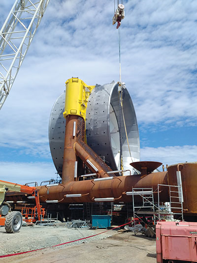
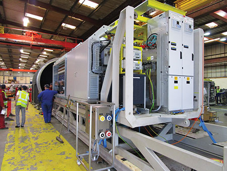
The 2 mW turbine is a permanent magnet ring generator that measures 16 m (50 ft) in diameter. The generator is a bi-directional machine, working on both stages of the tide, capable of generating power as the tide ebbs and floods, with an average normal operating speed of 6–8 RPM. The low rotational speed and turbine design mean that it is expected there will be no impacts on marine life. The generator assembly includes the generator itself with an output voltage of around 750 V, winding protection system, inverters (similar to those used in large wind turbines), controls, step-up transformer, and main disconnection means, with an assembly output voltage of 13.8 kV.
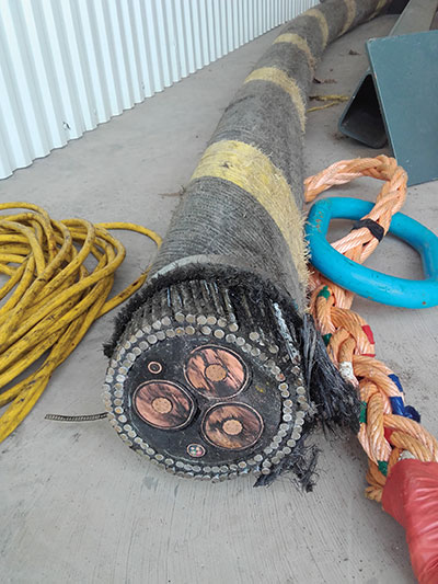
The 34.5 kV sub-marine cable used to carry the current to the shore from the first generator of this project is approximately 3.2 km in length. This special cable includes high voltage insulated conductors, a start-up control voltage cable, and an optical fiber cable to transmit controls from shore and critical data from the generator to shore.
This Cape Sharp Tidal turbine is equipped with monitoring devices to record performance data such as temperatures, current, voltage, and vibrations. The turbine is also equipped with a sonar and hydrophones to monitor sea life interactions with the device. The information gathered will be used to establish viability of proceeding with larger-scale generation projects in the Bay of Fundy.
The turbine subsea base is also large. The steel base frame is filled with more than 800 tonnes of concrete to hold the turbine in place given the tremendous forces in the Bay of Fundy.
Electrical Inspections and Approvals
The turbine installation was done in compliance with the 2015 Canadian Electrical Code (CE Code). One challenge we had was the limitation of 100 kW in CE Code Section 64. Section 64 defines a hydrokinetic power system as — a system operating as an interconnected or stand-alone system and consisting of one or more hydrokinetic turbines that convert the kinetic energy of flowing water into electrical energy with a rated output up to and including100 kW.
During the development of Section 64 for the 2012 CE Code, the task group assigned to develop the seed document started off with separate requirements for both small and large hydrokinetic power systems – similar to the existing requirements for small and large wind systems. The task group established the same requirements for both small and large hydrokinetic power systems and then decided to amalgamate the requirements into one subsection of Section 64 (64-600). Unfortunately, the definition did not get revised to reflect the decision. As a result of this Cape Sharp Tidal project, a code proposal was submitted to delete the words “with a rated output up to and including 100 kW” from the definition so the rules in Section 64 would apply to all hydrokinetic power systems.
Approval of the turbines was done by means of Field Evaluation/Special Inspection. Field Evaluation of the turbines also had challenges. The first task was to establish the standards to use, in addition to the SPE-1000 Model Code for the field evaluation of electrical equipment. The first obvious safety standard was CSA Standard C22.2 No. 100 Motors and generators, but this standard only covers the generator portion of the turbine assembly. Other CSA engineering and certification standards used for this project included C68.10 Shielded power cable for commercial and industrial applications, 5–46 kV, C88 Power transformers and reactors, C22.2 No. 14 Industrial Control Equipment, C22.2 No. 31 Switchgear Assemblies, C22.2 No. 51 Armoured Cables, C22.2 No. 94 Special purpose enclosures, C22.2 No. 107.1 General Use Power Supplies, C22.2 No. 107.3 Uninterruptible Power Systems, C22.2 No. 210 Appliance Wiring Material Products, C22.2 No. 239 Control and Instrumentation Cables, C22.2 No. 244 Switchboards, C22.2 No. 273 Cablebus, C22.2 No. 286 Industrial control panels and assemblies, and C22.2 No. 2556 Wire and Cable Test Methods. This dealt with the components but not the interconnection of components; for this, Sections 2, 4, 8, 10, 12, 14, 16, 26, 36, 64, and 84 of the CE Code, Part I were used.

Other challenges for the field evaluation process included testing of the enclosure for the control equipment, and the generator itself. The enclosure for the control equipment (that in the final assembly) is located on the subsea base intended to be installed 46 m (150′) under the surface of the water. The pressure test for this was completed in Scotland where the pressure vessel was manufactured. The performance testing for the generator created unique challenges, as the generator was the first of its kind and size, and the generator had to be located deep in the water to run. In this case, permission was granted by the local authority having jurisdiction to allow the generator to be connected for output and temperature testing prior to completion for the field evaluation.

In my 32 years of involvement in the electrical industry, I have had opportunity to work on some amazing projects, and I feel blessed to have also this unique opportunity to work on a project that will have such a positive impact on the large-scale generation of safe clean electrical power for years to come.
Permission for the use of all photos from this project is granted by Simon Cawthorne of Open Hydro.