
This article is a companion to another article in the March/April 2020 edition of the IAEI Magazine, entitled “Connections of Normal and Emergency Power Sources for Homes.” The last few years have seen many new products introduced to the residential electrical market to address these connections. These new products are worthy of discussion in the context of this article as these products may be new to users of the NEC. Two additional types of connections will be discussed in this follow-up article. These are (1) the meter-collar adaptor (MCA) and (2) the microgrid interconnect device (MID), which was introduced in the previous article.
Meter-collar adaptors have been around for decades. A common adaptor used throughout the Midwest is an under-meter surge arrestor. These surge protection devices have been marketed by utilities to help reduce the impact of surges on home appliances caused by lightning and utility distribution failures. Over the past decade, MCAs have been used to make connections for solar PV systems. Several companies, including ConnectDER, San Diego Gas and Electric (SDG&E), and Tesla, have produced devices that plug directly into a standard self-contained meter base and allow the meter to be then plugged into the MCA. The primary barrier to the use of these MCAs has been the fact that the meter enclosure is generally under the jurisdiction of the serving utility. Since SDG&E sells these devices, this barrier does not exist in their service territory. However, for other nearly 3,000 utilities throughout the United States, each one must approve these devices.
Fortunately, many utilities throughout the United States have agreed to allow MCAs to be used in their service territories. The fact that SDG&E not only allows these devices but actively markets them to their customers has undoubtedly helped other utilities to be more willing to accept these MCAs. Even though the approval to install an MCA is up to the approval of the serving utility, the rules for the connection are governed by NEC 230.82(6), Services, Article 250, Grounding, and Article 705, Interconnected Power Production Sources. The key advantage of these devices is the simplicity in which they allow for connections to be made to a utility service, especially for larger systems that commonly use a supply-side interconnection per NEC 705.11.
The first devices related to solar photovoltaic (PV) systems contained a connection to the service with an integrated 60-amp circuit breaker. For example, an MCA with a 60-amp breaker would allow for a connection of up to a 12kW PV system without having to deal with busbar ampacity issues common with PV interconnections on the load side of the service disconnecting means. While PV interconnections have been a common application of MCAs, with the advent of electric vehicles (EVs) and energy storage systems (ESSs), the application of these devices is expected to expand over the next few years.
In much the same way that an MCA allows for larger systems without having to upgrade the utility service equipment, an MCA that is also listed as an energy management system (EMS) could be used to add large controllable loads like an EV charger. Consider a 100-amp service for a home that Article 220 shows is on the borderline of needing a service upgrade. Now the customer is interested in purchasing an EV because of the outrageous cost of gasoline. Adding an EV charger, without an EMS, on the load side of the service disconnecting means will require a service upgrade. Many utilities offer 100-amp, 200-amp, and 400-amp service options. Any upgrade will cost thousands of dollars, making the purchase of an EV less cost-effective and unaffordable for many.
Is the meter collar and associated breaker in an MCA considered a Service Disconnect?
The NEC permits the connection of “Solar photovoltaic systems, fuel cell systems, wind electric systems, energy storage systems, or interconnected electric power production sources, if provided with a disconnecting means listed as suitable for use as service equipment” to the supply side (utility side) of the normal service disconnecting means in 230.82(6) [2020 NEC] and load management devices and other systems in NEC 230.82(4) and (5). The MCA, where installed in the utility meter socket, is considered a service disconnecting means for an interconnected electric power production source like PV or even a bi-directional EV Power Transfer System. The MCA, where installed in the utility meter socket, could also be considered a service disconnecting means for a load management device if supplying only an EV charger. Many users of the NEC mistakenly see a connection on the supply-side and immediately want to group the disconnecting means for this connection with the normal service disconnecting means. This is a point of confusion for many users of the NEC that requires some explanation.
Does the MCA service disconnect need to be grouped with the normal service disconnect?
The requirements of 230.72(A) apply to each service disconnecting means. A home with a normal service disconnecting means and an additional service disconnecting means for any system under NEC 230.82(4), (5), or (6) has two separate service disconnecting means. One service disconnect means can be in the basement whereas the MCA will be at the utility meter socket on the outside of the house. The two separate service disconnecting means are not required to be grouped.
In general, the normal service disconnecting means, when it is comprised of two to six disconnects, must be grouped in one location [230.72(A)]. If another individual service disconnecting means is made up of multiple disconnects, those disconnects must be grouped and follow the requirements of NEC 230.72(A). An additional service disconnecting means for fire pumps, emergency, and standby systems [NEC 230.82(5)] must not be grouped with the normal service disconnecting means to prevent inadvertent operation of these switches [230.72(B)]. The reason for the separation requirement for these special services is that, during emergencies, these systems may be required to stay on for safety reasons. The separation helps the operator to consider the consequences of operating these separate disconnects in an emergency situation.
The NEC is silent on where the disconnecting means for load management devices [in NEC 230.82(4) or (5)] or 230.82(6) systems must be located. They are clearly not part of the “normal service disconnecting means,” and not on the list of those systems required to be separated. Therefore, the correct interpretation of the NEC language is that the location of disconnecting means for load management devices or 230.82(6) systems can either be separate from or grouped next to the normal service disconnecting means. This additional disconnecting means is a service disconnecting means that is permitted to include up to six disconnects.
Summarizing these concepts of number of disconnects and grouping of service disconnects, here is a list of the concepts for clarity:
- Systems called out in 230.82(4), (5), or (6) are permitted to be connected on the utility side of the normal service disconnecting means.
- A disconnecting means for these 230.82(4), (5), or (6) systems connected at the meter enclosure is a service disconnecting means
- The MCA service disconnecting means is not required to be grouped with the normal service disconnecting means [230.72]
To illustrate these concepts in an example, consider a home in New England with a utility meter on the exterior and the normal service disconnecting means in a basement electrical panel. The EVMA with its disconnect is installed in the exterior meter socket and the conductors from the disconnect run the electric vehicle charger located anywhere on the premises. The bonding of the EVMA service disconnecting means is performed like any service disconnecting means and the locations of the normal and EVMA service disconnecting means are not in the same location. No code violation exists with this example.
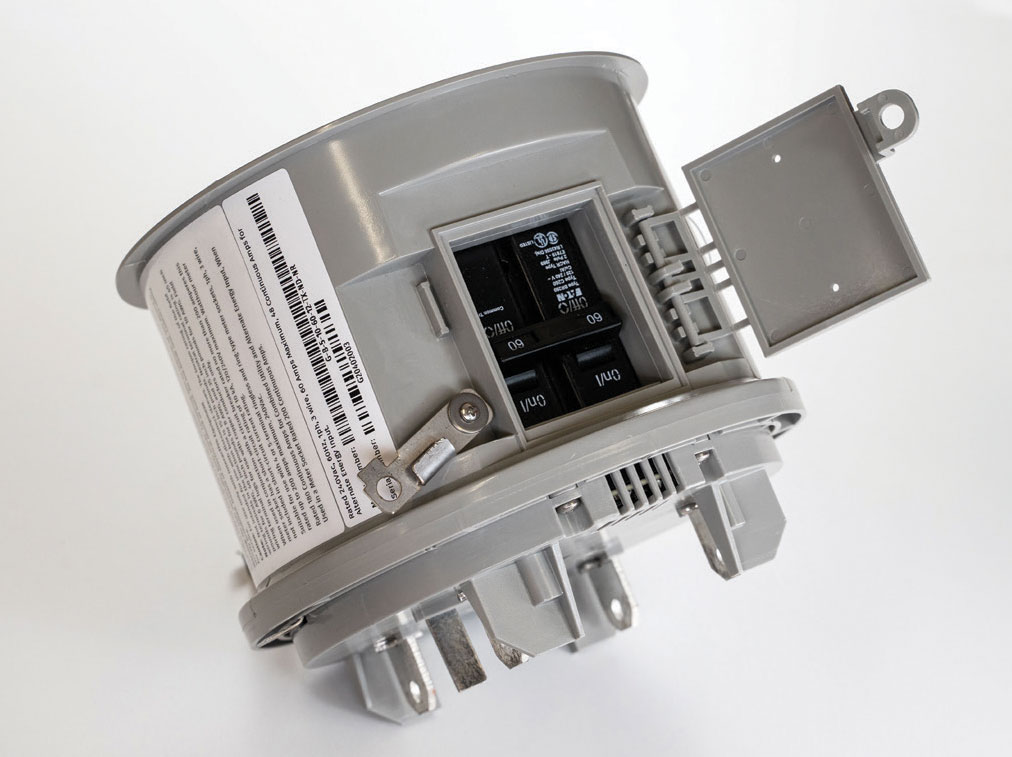
Let’s go back the example of an MCA certified as an EMS to directly supply an EV charger. Now that same EV charger is on a circuit that can be interrupted whenever the load exceeds the rating of a 100-amp service. Since the MCA monitors all power flowing through the service, should the homeowner decide to plug in their EV on a hot summer afternoon when their house is drawing full power, the MCA simply keeps the EV from charging until the house load gets below 60-amps. Once that occurs, the power to the EV charger is restored, and the car can be charged. An even more useful variation on this theme is for future MCAs to communicate with the EV charger and actually control charging current directly based on the service load. This simple addition at the meter socket not only prevents a service upgrade but also allows for a simple connection on the outside of the house. This negates the need to run a circuit from a distribution panel that may be in the basement and may not have room for a two-pole breaker. Is this futuristic? No, there are products being developed and certified for this very purpose (see Figure 1).
So what does the NEC say about this idea? If the MCA is certified for connection to a bi-directional EV Power Transfer System (Article 625), and it is limiting power to an EV in charging mode, it is operating as a load management system. As a load management device, the EV charging load connected to this device does not necessarily add load to the existing service since it is controlled.
Article 220 of the NEC covers minimum service size based on the number of load devices connected to the service. In Article 750, energy management systems are covered, and in NEC 750.30, the load size is based on the settings of the energy management system. The EV MCA could be certified as a load management device that shuts down the EV charging system whenever the load on the utility service approaches its rating. Rather than using the old-school method of estimating electrical loads, as covered in Article 220, the NEC allows the load management system to measure the actual service load and disconnect its load whenever the rest of the load on the service nears the service capacity. This means that the service size does not need to be increased when this type of MCA is installed. In a worst-case scenario, if the service was always run at capacity and an EV MCA was installed on that service, the EV charger would never receive power. Fortunately, normal residential services in the United States don’t operate anywhere near their ratings for long periods, so the amount of time an MCA would have to disconnect or regulate the EV charger on a residence is quite small.
Additionally, since the EV MCA does not require that the service size be increased, the service is not being changed. Therefore, the service would not be required to be brought into compliance with the most recent code requirements for residential services.
How does Article 625 apply to the EV MCA?
Article 625 was previously termed “Electric Vehicle Charging” in the 2017 NEC and was updated to the current term, “Electric Vehicle Power Transfer System,” in the 2020 NEC. In either edition of the NEC, the pertinent section related to the EV MCA is NEC 625.42 relating to the rating of the EV charging system and the sizing of conductors for the EV system. The NEC considers a typical EV charger not connected to a load management device as a continuous load at the maximum current rating of the device. For instance, if the EV charger is a Level 2 device operating at 32-amps, 240Vac, that is the continuous load it presents to the conductors and the service. The conductors must be sized for 40-amps (32A x 1.25 = 40A), and the minimum size circuit breaker to protect the conductors must be 40-amps.
Where the MCA is a load management device, the conductors from the MCA to the EV charging system must be sized according to the continuous current rating so the circuit breaker and conductors will be identical to the size and ratings required for any EV system. However, the key difference comes in the setting of the load management system. An MCA with a relay for the EV load is a simple load management system designed to shed the EV load whenever the electrical load on the service with the EV charger load exceeds the rating of the service. This effectively reduces the impact of the EV load on the service to zero-amps allowing even the smallest of residential services to have an EV charger installed on it. Without a load-management function on an EV charger, most smaller services are insufficient for the additional load of an EV charger and would be required to be upgraded based on the requirements of NEC 625.42.
MICROGRID INTERCONNECT DEVICES
In 2017, Tesla introduced a microgrid interconnect device (MID) product called the Backup Gateway. This product was the first separate device specifically designed for the residential market to connect both power sources and site loads in an enclosure with a MID. A MID, as defined by the NEC, is a device capable of disconnecting power sources and loads from the serving utility and reconnecting those power sources to the utility as needed. The MID is similar to a transfer switch, but it usually includes power sources that parallel with the utility. Historically, transfer switches and equipment have transferred power from the utility source to another source, such as a diesel generator. Those very common systems rarely have, if ever, included power sources on the load side that paralleled with the utility system.
While not available yet, an obvious next step for an MCA is to incorporate a whole-house relay and be certified as a MID. During a utility outage, an MCA could be used to isolate the whole house from the utility and allow the house to operate as a microgrid. The benefit of this approach is that it does away with the extra box that houses the MID as with the existing MIDs on the market. Another benefit is that it may be easier to install an MID on a home with an all-in-one service panel.
Interconnected Systems Built Around the MID
The world of backup power is changing again, and it is becoming more common for parallel power sources to be located on the load side of transfer equipment. Therefore, MIDs and transfer equipment intended to allow for parallel sources on the load side must be evaluated for this special condition when used in these types of systems. All this is to say that MIDs and transfer equipment that accommodate load-side power sources are being evaluated differently than old-school transfer equipment. Back to the example of the Tesla Backup Gateway, this device is not only a MID, but it also provides for the connection of solar photovoltaic (PV) systems (Article 690) and energy storage systems (ESS) (Article 706). Additionally, this device and similar devices from other manufacturers provide separate load connections for optional standby system load (Article 702) and non-standby loads not included in the local microgrid.
The introduction of the Tesla multi-function listed MID has encouraged many competitors to develop similar products with similar capabilities. These products include the SolarEdge Home Backup Interface, the Enphase IQ System Controller, and the Franklin aGate, to name a few. These devices are listed to connect multiple PV and ESS power sources and are also listed to do load management of the load supplied by the microgrid power sources as required by NEC 702.4 for these optional standby microgrid systems. Some enforcers of the NEC have raised questions about the internal ampacity ratings of these devices since loads and power sources are included in this listed equipment. Their concern is that Section 705.12 related to load-side source connections be properly addressed inside the listed equipment. While it is natural to question the internal ratings of listed equipment, the manufacturer’s instructions included with the listed equipment is the document used to enforce what can and cannot be connected to this multi-function equipment.
Section 705.12(B) in the 2017 NEC and 705.12 in the 2020 NEC address load-side connections of sources. These requirements are intended to address the connection of power sources using commonly available distribution equipment. Common distribution equipment did not necessarily anticipate the combination of power sources and loads. Therefore the requirements of 705.12 are needed to ensure that equipment is not operated outside of the listed ratings of the equipment.
This concern does not exist with purpose-built listed electrical equipment that is designed to combine power sources and/or loads. The certification process and the manufacturer’s instructions and limitations on that equipment ensure that the ratings of the equipment are observed. This relieves enforcement of the need to scrutinize the equipment’s internal ratings and focuses on the concern that the equipment is being used as intended in the long-standing tradition of NEC 90.7. The 2023 NEC will likely include language in 705.12 that reinforces the fact that purpose-built equipment used in accordance with its listing is not required to follow 705.12 internally.
Examples of MID Applications
The reason these purpose-built multi-function devices were developed in the first place is that the basic rules of NEC 705.12 can be very limiting when employing multiple power sources in a local microgrid. While the requirements of 705.12 are not enforced inside listed equipment, the connections of this equipment to premises distribution equipment do have to follow these basic rules. To illustrate how these devices are being employed in code-compliant installations, several examples are provided.
MID as Service Equipment
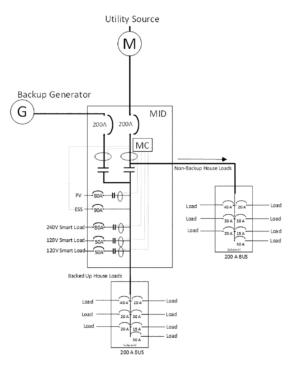
The devices mentioned earlier in this article are all suitable for use as service equipment. Each product has a means of receiving service conductors and performing the required bonding of the service grounded conductor to ground as required by NEC 250.24. The following diagram shows an example of a typical multi-function MID used as service equipment (see Figure 2).
MID installed on the load side of service equipment
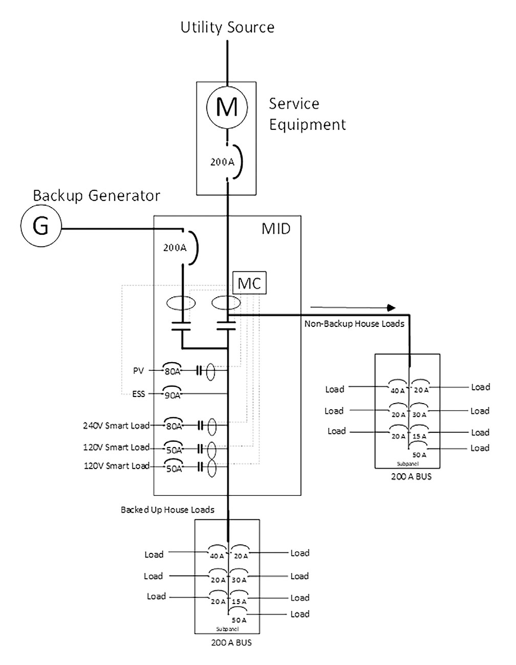
An even more common application of this equipment is where the multi-function MID is installed downstream of the main service equipment. This raises the primary issue of ensuring that the upstream equipment meets any relevant requirements of NEC 705.12. If the service equipment only has the service disconnecting means, this provides for the simplest installation of a multi-function MID. For example, if the main service disconnect is a 200-amp circuit breaker in a meter-main configuration, the MID can simply be installed directly to the load side of the main breaker. There is no need for a 200-amp circuit breaker on the input to the MID as would be required when the MID is the service equipment (see Figure 3).
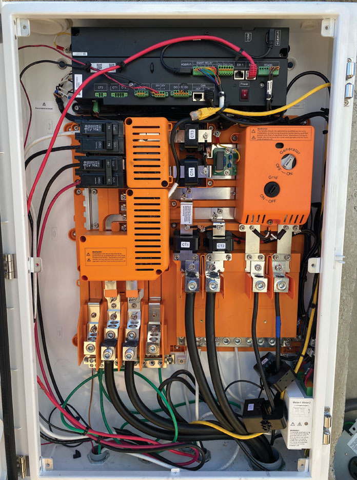
If the MID is managing an ESS and PV source inputs, then those additional sources need to be evaluated as part of the Energy Management System (EMS), which can include both Power Control Systems [NEC 705.13] and load management devices [Article 750]. The internal bussing of the MID is certified to handle the maximum currents that the EMS allows. Load-side busbar calculations, such as those required in 705.12(B)(3) are not necessary inside the listed equipment as those loading issues are addressed in the manufacturer’s instructions as part of the product listing (see Figure 4).
Loads connected to the load side of multi-function MID equipment
There has been some disagreement in the enforcement community as to whether loads run as part of a local microgrid in island mode are required to meet the requirements of optional standby systems in 702.4(A) or stand-alone systems in 710.15. The load control requirements differ significantly from each other. Optional standby systems require that the source for automatically transferred loads either be sufficient to carry the entire load or that load control limit the load to the size of available sources [see 702.4(B)(2) in the 2020 NEC]. In contrast, the language of 710.15(A) requires only that the sum of the sources be large enough to power the largest load.
Neither method will guarantee that the system will work properly. The NEC is intended to provide “…practical safeguarding of persons and property from hazards arising from the use of electricity.” [NEC 90.1(A)]
It is easy to see how these methods can be confusing to enforce. It is conceivable that some plans examiners may want to see detailed explanations of how a load management system meets the stated requirements of 702.4(B)(2)(b) of the 2020 NEC. The 2023 NEC will illuminate this issue for users of the NEC on this issue. The correlating committee task group that convened on this issue adjusted the language of 702.4. The emphasis in the 2023 NEC is now placed on listed EMS equipment. The purpose of EMS equipment is to limit the load to the available source power. Section 220.70 was just added to the 2023 NEC and addresses energy management systems (EMS).
In a local microgrid, the sources in the microgrid must work together to meet the operating load (see an example of a system in Figure 5). If the operating load exceeds the source capability of the microgrid one of two actions are taken by the microgrid EMS control system. Either (1) some of the load is disconnected to reduce the load to within the source capability, or (2) all of the load is disconnected. In either case, none of the loads are damaged or operated outside of their rated voltage and current parameters. The first case is generally the desired mode as the greatest number of loads are kept energized in island mode. However, the second case, where all load is de-energized, is very similar to the common situation of utility power outages where no optional standby system exists.
The key word in the title of Article 702, Optional Standby Systems, is “Optional.” By its very definition, the load run by these systems is optional and is not required to meet the much more stringent supply requirements of Article 700, Emergency Systems, or Article 701, Legally Required Systems. Clearly, the customer who spends a lot of money on an optional standby system will expect it to operate during utility outages. If it does not meet the customer’s expectations, this is not the fault or responsibility of enforcement. The fault may relate to one or more issues: (1) poorly communicated expectations by contractor or customer, (2) equipment failures, or (3) improper operation of the system. If the EMS shuts down the load due to a lack of available power, the customer may be upset, but the NEC is not violated. Most, if not all, multi-function MID equipment is evaluated and listed as an EMS and therefore meets the intent and requirements of 702.4.
With this understanding of the operation and control of EMS like a multi-functional MID, it becomes clearer that 702.4 is the more appropriate code reference for microgrids operating in island mode. To properly operate and control stand-alone systems or isolated microgrid systems, it is also valuable to incorporate an EMS to get the best service for the system. However, the basic requirement is that a source supplying the stand-alone system need only be sufficient for the largest single load.
Summary
There are numerous ways to connect solar and energy storage systems to homes for normal and backup power needs. Meter collar adaptors (MCAs) provide a simple and compact method for solar PV systems that may also be used to accommodate special controlled loads such as EV chargers. The service disconnects for these devices are not required to be grouped with the main service disconnecting means for the house. Microgrid interconnect devices (MIDs) may be incorporated into meter collar adaptors or may be installed separately as part of the service disconnecting means or on the load side of the service disconnect. These MIDs often have multiple functions that not only provide isolation for microgrids during a power outage but also connect solar, energy storage, smart load, and even generators. The advent of these specifically listed devices is making the connection of new power sources and new loads more straightforward. These devices also dramatically reduce the need for service equipment upgrades. The simplification of these connections with these devices is sure to make the installation of this complex equipment better for installers and enforcers.