That was my overriding perspective as one of the committee members that helped to develop the Interstate Renewable Energy Council’s (IREC) Solar Permitting Plan Review training course. It is a perspective gained from real-world experience. The project was funded through a Department of Energy (DOE) grant to IREC as the code official component of the Solar Training and Education for Professionals (STEP) program. See the September/October 2018 IAEI Magazine for a complete overview of this award-winning effort. When the IREC staff member asked our committee to identify the primary elements for approval of a residential PV design we identified three: structural, fire, and electrical.
There can be some crossover between the elements. For example, the module support system (rack) is a structural element that is also a component (along with the module fire type) of fire classification for the entire assembly. The roof array must at least achieve the same fire classification (A, B, or C) as is required for the existing roof. In addition, if the rack system is to be used to bond the module frames then the rack system must have been evaluated to the bonding attribute of UL 2703, Standard for Mounting Systems, Mounting Devices, Clamping/Retention Devices, and Ground Lugs for Use with Flat-Plate Photovoltaic Modules and Panels in combination with the specific module. UL 2703 includes (3) attributes; fire classification, bonding/grounding and structural. Certification to one attribute does not guarantee certification to all. Even if the plan is correct did the installation crew follow the approved plan? A robust field inspection is always essential.
Does your jurisdiction require compliance with access pathways and fire setbacks for first responders? See Section 324 of the 2018 International Residential Code (IRC). If so, is the array located on the roof in compliance with the required dimensions? Are the access pathways and ridge setbacks indicated on the plan? Roofs can be complex. It is much easier to relocate an array on a paper or electronic plan rather than after real-world installation. Competent design combined with a plan review by a qualified individual equates to efficient installation.
What about the electrical design? Review of the electrical plan is usually more complex than either the structural or fire elements. There are a variety of system types including central inverter, micro-inverter and ac module. The specific design for each type can vary widely. Some plan reviewers are not as experienced with electrical design requirements and photovoltaic (PV) system electrical design will differ from that of a standard premises electrical distribution system. The IREC concept was to relate a PV plan review to similar elements that plan reviewers may already encounter. There are electrical elements that are unique to PV systems but also many that are not. The differences must be appreciated but that is true of all electrical systems.
For example, the National Electric Code (NEC) rules in Article 517 for a health care facility will be different than those for a dwelling unit. Proper application of the NEC according to 90.3 is always necessary. The general rules of Chapters 1–4 may be modified by Chapters 5–7 for special occupancies, equipment or conditions. The requirements of Chapters 5–7 can also supplement or modify each other so Chapters 5-7 will supplement or modify Chapters 1–7 as applicable.
NEC training regarding PV systems invariably focuses on Article 690, Solar Photovoltaic (PV) Systems, for the specific equipment and Article 705, Interconnected Electric Power Production Sources, for the interconnection to the premises electrical system. This is appropriate because these articles are where the specific rules for the technology are found. But we must also be sure that the installation is in compliance with the applicable requirements of NEC Chapters 1-4. New technology may seem complex but a plan reviewer or inspector is often applying a greater quantity of technical requirements for residential dwelling unit than a residential PV system. If you are qualified to inspect the home’s electrical installation located within the structure below the roof and the array, then the PV system should be within your abilities.
My jurisdiction is a busy one for PV installations. The very warm valley climate necessitates constant and large HVAC loads. Combine those large electrical loads with the utility rate structures and PV installations become a very attractive financial investment. Our permits for residential PV installations have numbered between 4000 and 5000 per year for the last several years. That quantity of permits has provided us with a solid basis for the identification of the most common design and installation problems.
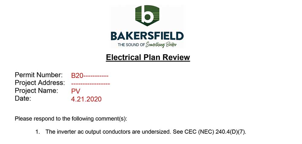
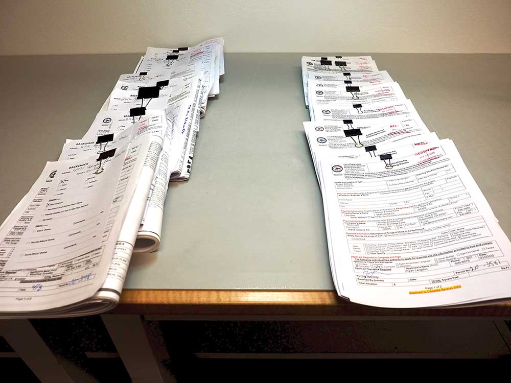
From January through November of 2016 this jurisdiction provided plan review for 4161 residential PV systems. 542 (13%) could not be approved due to non-compliance with applicable code rules. Of that total 286 (7%) were for fire/structural reasons and 256 (6%) were for violations of the NEC. There was one electrical design problem that was far more common than any other that year. It has not changed in the years since. Though the initial electrical design rejection rate has increased to approximately 10% for the first quarter of 2020 the same common problem remains prevalent.
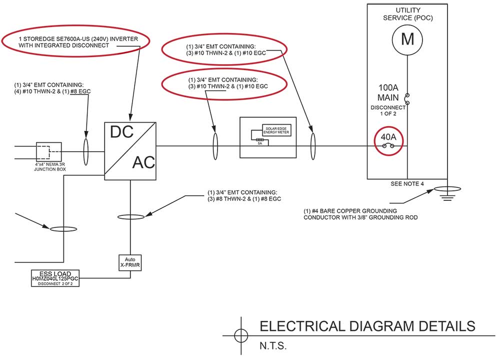
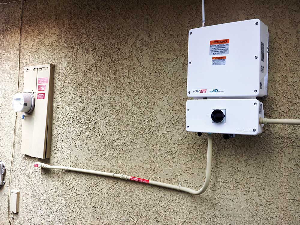
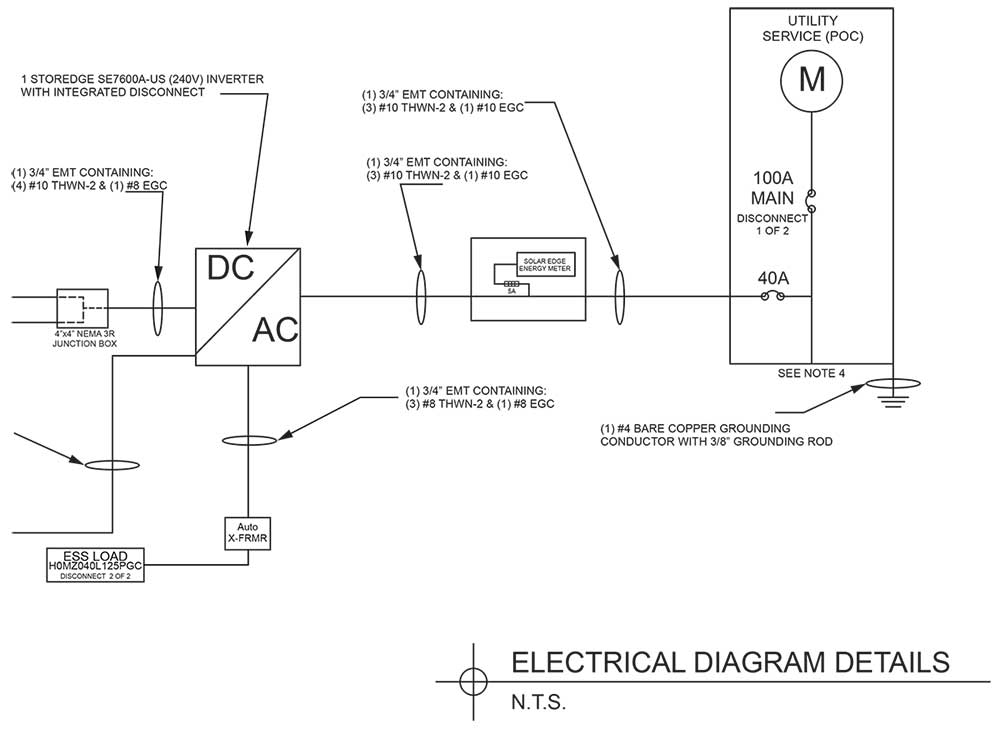
The common problem involves the central inverter power source output circuit conductors that were, and still often are, undersized. Specifically, 10 AWG is specified where a minimum of 8 AWG is required. Central inverters rated in the 6 kW to 7 kW range are very common. The minimum overcurrent protection for an inverter must be 125% of the rated output current. This will equate to a 35- or 40-amp circuit breaker for inverters in this size range. But all too often a designer will specify a #10 inverter output conductor protected by a 35 amp or 40-amp circuit breaker. The ampacity tables of Article 310 will provide ratings based on the conductor insulation type and size. Conditions of use must also be considered. But NEC 240.4(D)(7) cannot be ignored. The 10 AWG copper conductors are limited to a maximum of 30-amp overcurrent protection by this NEC requirement.
PV installations are not just subject to the rules of Article 690 and 705. The general rules of NEC Chapters 1–4 are applicable and must be well known by the designer, installer, and inspector. A proper plan review of a residential PV system involves far more than the size of the inverter ac power source output conductors. But don’t inadvertently overlook the most common design problem while checking the other elements. It is always the basics.




Find Us on Socials