Definitions
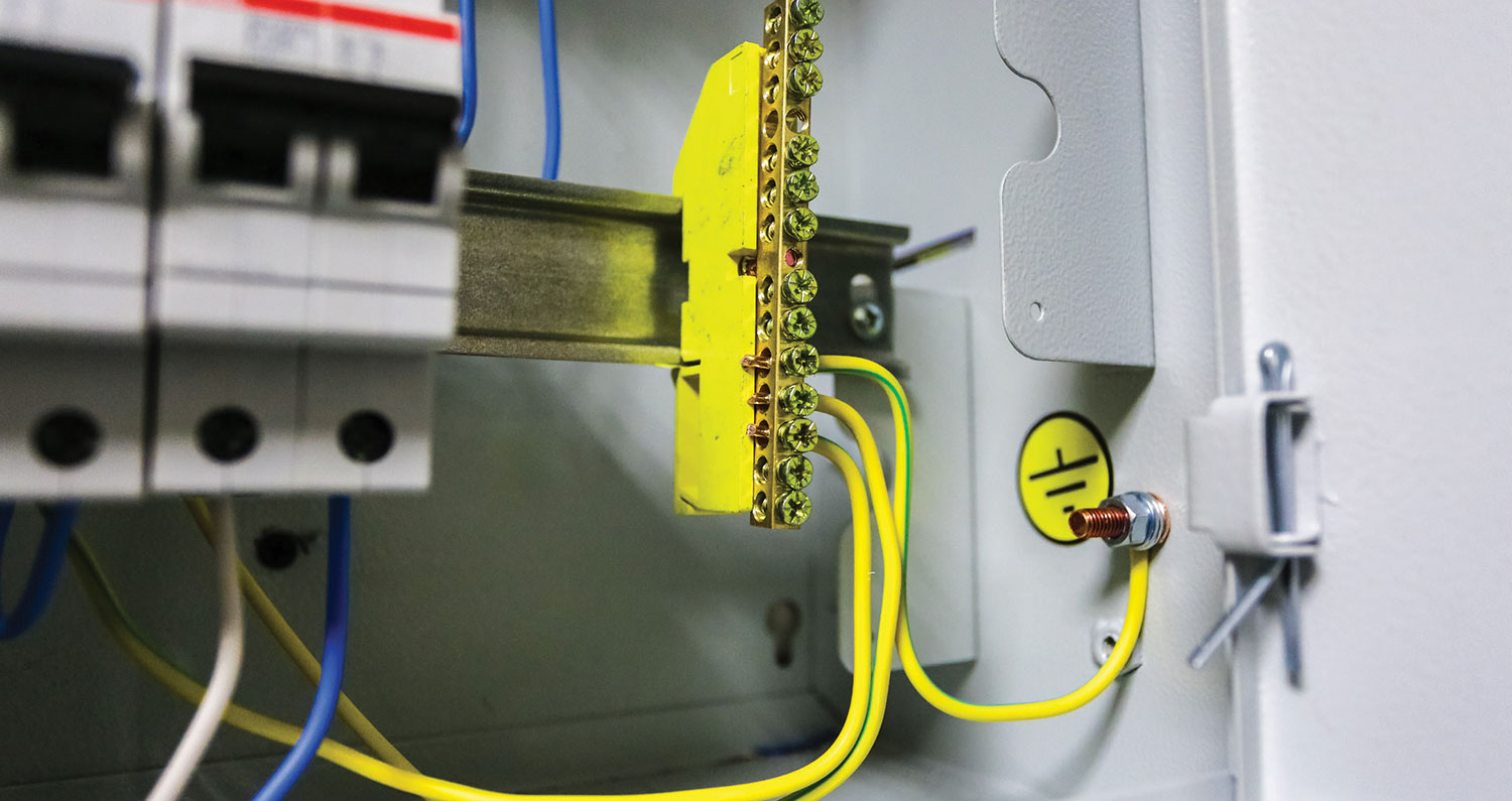
Bonding (Bonded): “The permanent joining of metallic parts to form an electrically conductive path that will ensure electrical continuity and the capacity to conduct safely any current likely to be imposed.” N
Bonding jumper, Main: “The connection between the grounded circuit conductor and the equipment grounding conductor at the service.”N
Main bonding jumper
The main bonding jumper is one of the most critical elements in the safety grounding system. This conductor is the link between the grounded service conductor, the equipment grounding conductor and in some cases, the grounding electrode conductor. The primary purpose of the main bonding jumper is to carry the ground-fault current from the service enclosure as well as from the equipment grounding system that is returning to the source. In addition, where the grounding electrode conductor is connected directly to the grounded service conductor bus, the main bonding jumper ensures that the equipment grounding bus is at the same potential as the earth.
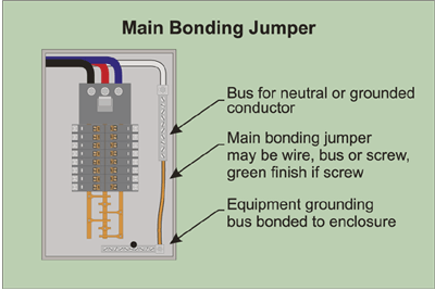
For a grounded system, Section 250-28 requires that an unspliced main bonding jumper be used to connect the equipment grounding conductor(s) and the service-disconnect enclosure to the grounded conductor of the electrical system. The connection is required to be made within the enclosure for each service disconnect.
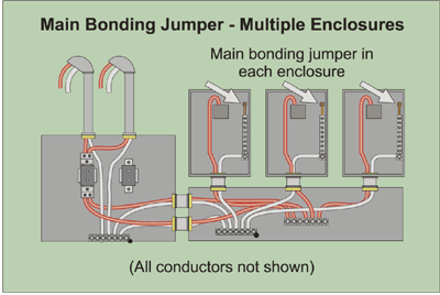
An example of this is where two or more service disconnecting means in individual enclosures are grouped at one location. This type of installation often is made with a wireway or a short section of busway installed downstream from the metering equipment. In other cases, a wireway or short section of busway is installed ahead of metering and is supplied by a service lateral or service-entrance conductors. Sets of service-entrance conductors supply each of the service disconnecting means. Service disconnecting means are installed from the wireway or auxiliary gutter. (If there are nipples between the disconnecting means and the metal or nonmetallic trough, the trough meets the definition of a wireway from Article 362 rather than an auxiliary gutter from Article 374.) Section 250-28 requires a main bonding jumper be installed in each service disconnect enclosure. As previously mentioned, Section 250-24(b) requires that the grounded service conductor be brought to each service disconnecting means and be bonded to the enclosure. The main bonding jumper is the means to accomplish this requirement.
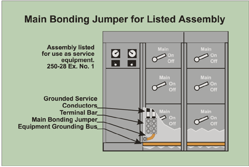
The rules are a little different where more than one service disconnecting means is in a common enclosure. This equipment usually consists of listed switchboards, panelboards or motor control centers.. Where more than one service disconnecting means is located in an assembly listed for use as service equipment, Section 250-28 Exception No. 1 permits the grounded service conductors to be run to a single grounded conductor bus in the enclosure and then be bonded to the assembly enclosure. This means that only one main bonding jumper connection is required to be installed from the common grounded conductor bus to the assembly enclosure. The sections of the assembly are bonded together by means of an equipment grounding conductor bus or by being bolted together.
Exception No. 2 to Section 250-28(b) permits alternate means for bonding of high-impedance grounded neutral systems. See Chapter Four of the IAEI Soares Book on Grounding for methods and requirements for grounding high-impedance grounded neutral systems. Also see NEC® Sections 250-36 and 250-186 for the specific requirements and allowances.
The main bonding jumper is permitted to consist of a wire, bus, screw or other suitable conductor. It must be fabricated of copper or other corrosion-resistant material. Aluminum alloys are permitted where the environment is acceptable. In addition, where the main bonding jumper consists of a screw, it must have a green finish that is visible with the screw installed. This green finish assists in identifying the bonding-jumper screw from the other screws that are on or near the neutral bus. See Sections 250-28(a) and (b).
Functions of Main Bonding Jumper
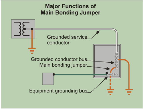
The main bonding jumper performs three major functions:
1. Connecting the grounded service conductor to the equipment grounding bus or conductor and the service enclosure.
2. Providing the low-impedance path for the return of ground-fault currents to the grounded service conductor. The main bonding jumper completes the ground-fault return circuit from the equipment through the service to the source as is illustrated in Figure 5-4.
3. Connecting the grounded service conductor to the grounding electrode conductor. Under certain conditions given in Section 250-24(a)(4), it is permitted to connect the grounding electrode conductor to the equipment grounding terminal bar rather than to the terminal bar for the grounded service conductor. This scheme is common on larger switchboard services and is necessary for proper operation of certain types of equipment ground fault protection systems. See Chapter 15 of the IAEI Soares Book on Grounding for additional information on this subject.
Size of main bonding jumper in listed enclosures
Where listed service equipment consisting of a switchboard, panelboard or motor control center is installed, the main bonding jumper that is provided with the equipment is rated for the size of conductors that would normally be used for the service. The method for sizing of the main bonding jumper in listed service equipment is found in Underwriters Laboratories Safety Standard for the equipment under consideration and is verified by the listing agency. Therefore, if a main bonding jumper that is a bus bar, strap, conductor, or screw is furnished by the manufacturer as part of the listed equipment, it may be used without calculating its adequacy. Section 384-3(c) requires the equipment manufacturer to provide the main bonding jumper.
Size of main bonding jumper at single service-disconnect or enclosure
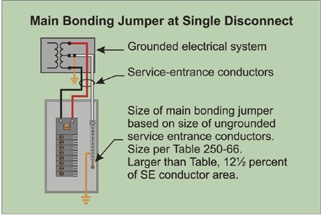
Since the main bonding jumper must carry the full ground-fault current of the system back to the grounded service conductor (which may be a neutral), its size must relate to the rating of the service conductors which supply the service. The minimum size of the main bonding jumper is found in Table 250-66 as required by Section 250-28(d). This relationship is based on the conductor’s ability to carry the expected amount of fault current for the period of time needed for the overcurrent device to open and stop the flow of current.
For example, where 250 kcmil aluminum service-entrance conductors are installed, the main bonding jumper is found to be No. 4 copper or No. 2 aluminum by reference to Table 250-66.
The size of the main bonding jumper does not directly relate to the rating of the service overcurrent device. Do not attempt to use Table 250-122 for this purpose. Table 250-122 gives the minimum size of equipment grounding conductors for feeders and circuits on the load side of the service.
Sizing of main bonding jumper for parallel service conductors
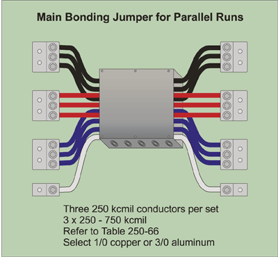
Where service conductors are installed in parallel, (connected together at each end to form a larger conductor) the total circular mil area of the conductors connected in parallel for one phase are added together to determine the minimum size main bonding jumper required. See Section 250-28(d). For example, where three 250 kcmil conductors are connected in parallel per phase, they are treated as a single 750 kcmil conductor. By reference to Table 250-66 the main bonding jumper, if aluminum service-entrance conductors are used, is 1/0 copper or 3/0 aluminum.
Where the service-entrance conductors are larger than the maximum given in Table 250-66, Section 250-28(d) requires the main bonding jumper to be not less than 12½ percent (0.125) of the area of the largest phase conductors.
This is illustrated by the following example:
Three 500 kcmil copper conductors are installed in parallel as service-entrance conductors.
3 x 500 kcmil = 1500 kcmil.
1500 x .125 = 187,500 circular mils.
Since a 187,500 circular mil conductor is not a standard size, we next refer to Chapter 9, Table 8 to find the area of conductors.
The next conductor exceeding 187,500 circular mils is a No. 4/0 AWG conductor which has an area of 211,600 circular mils. It is always necessary to go to the next larger size conductor since the 12½ percent size is the minimum size permitted.
Follow a similar procedure for determining the minimum size main bonding jumper required for other sizes of parallel service-entrance conductors.
Bonding of service conductor enclosures
Special rules are provided for bonding enclosures on the line side of the service disconnecting means. This is due to the fact that this equipment does not have overcurrent protection on its line side such as feeders and branch circuits have. Fault current of sufficient magnitude must flow during a short period of time to allow the fuse on the line side of the utility transformer to open. The level of fault current and particularly the duration the current may flow could be much larger than would flow in a feeder or branch circuit as there is not an overcurrent device in series with the conductor.
The basic rule is that all metallic enclosures that contain a service conductor must be bonded together. The bonding ensures that none of the equipment enclosures can become isolated electrically and become a shock hazard should a line-to-ground fault occur. The bonding also provides a low impedance path for fault current to flow in so the fuse or circuit breaker on the line side of the electric utility transformer will open.
Sizing of equipment bonding jumper on line (supply) side of service.
Equipment bonding jumpers on the line side of the service and main bonding jumper must be sized to comply with Table 250-66. This is required by Section 250-102(c). For example, where 250 kcmil copper conductors are installed as service-entrance conductors, Table 250-66 requires a No. 2 copper or 1/0 aluminum bonding jumper.
Where the sum of the circular mil area of the service-entrance phase conductors exceeds 1100 kcmil copper or 1750 kcmil aluminum, the equipment bonding conductor must be not less than 12½ percent (0.125) of the area of the ungrounded phase conductors.
Sizing of equipment bonding jumper for parallel conductors
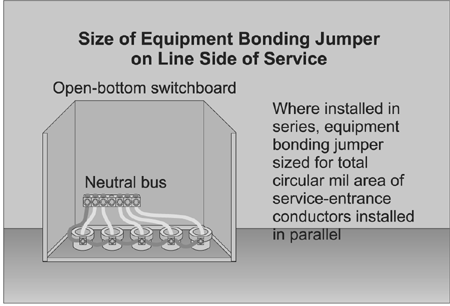
Two methods are provided for bonding service raceways that are installed in parallel. The first method is to add the circular mill area of the service-entrance conductors per phase together and treat them as a single conductor. The bonding jumper size is determined from Table 250-66 and is connected to each conduit bonding bushing in a “daisy-chain fashion.” This method often results in an equipment bonding jumper that is quite large and difficult to work with.
For example, if five 250 kcmil copper conductors are installed in parallel for a phase, the equipment bonding jumper for bonding the metal raceways must not be smaller than 3/0 copper.
This is determined as follows:
Five x 250 kcmil = 1250 kcmil.
1250 kcmil x .125 = 156,250 circular mils.
The next larger conductor found in Chapter 9, Table 8 is 3/0 with an area of 167,800 circular mils.
In this case, a 3/0 copper equipment bonding conductor must be connected from the grounded service conductor or equipment grounding bus to each metal raceway in series (daisy-chain fashion from one raceway to another).
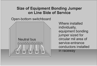
A more practical method of performing the bonding for services supplied by multiple raceways may be to connect an individual bonding conductor between each raceway and the grounded service conductor terminal bar or equipment grounding bus. This is permitted by Section 250-102(c). This will usually result in a smaller equipment bonding conductor which is easier to install.
Again, using the example above and referring to Table 250-66, the minimum size equipment bonding conductor for the individual raceways containing 250 kcmil copper service-entrance conductors is No. 2 copper or 1/0 aluminum. A properly sized equipment bonding jumper is installed from the terminal bar for the grounded service conductor or from the equipment grounding terminal bar to each conduit individually.
Different conductor material
Section 250-28(d) provides instructions on sizing the main bonding jumper or equipment bonding jumper on the supply side of the service where different conductor materials are used for the service-entrance conductors and the bonding jumper. The procedure involves assuming the phase conductors are of the same material (copper or aluminum) as the bonding jumper and that they have an equivalent ampacity to the conductors that are installed. This is illustrated as follows:
Assume aluminum phase conductors and a copper bonding jumper are installed.
Three 750 kcmil Type THW aluminum conductors are installed.
From Table 310-16, 385 amperes x 3 = 1155 amperes. The smallest type THW copper conductor that has an equivalent rating is 600 kcmil with an ampacity of 420.
Next, determine the total circular mil area of the copper conductors.
Three x 600 kcmil = 1800 kcmil.
1800 kcmil x .125 = 225 kcmil.
The next standard size is 250 kcmil copper which is the minimum size bonding jumper permitted to bond equipment at or ahead of the service equipment in this example.
Bonding service equipment enclosures
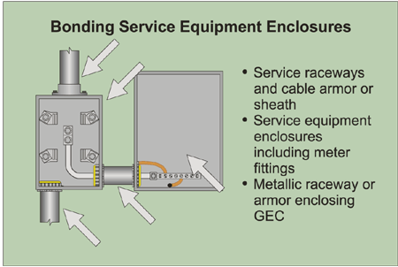
The Code requires that electrical continuity of service equipment and enclosures that contain service conductors be established and maintained by bonding. The items required to be bonded together are stated as follows in Section 250-92(a):
(1) The service raceways, cable-trays, cablebus framework or service cable armor or sheath.
(2) All service equipment enclosures containing service conductors, including meter fittings, boxes or the like, interposed in the service raceway or armor.
(3) Any metallic raceway or armor which encloses the grounding electrode conductor. (This subject is covered in detail in Chapter 7 of this text.)
An exception to this requirement for bonding at service equipment is mentioned in Section 250-92(a)(1). It refers to Section 250-84 which has rules on underground service cables that are metallically connected to the underground service conduit. The Code points out that if a service cable contains a metal armor, and if the service cable also contains an uninsulated grounded service conductor which is in continuous electrical contact with its metallic armor, then the metal covering of the cable is considered to be adequately grounded.
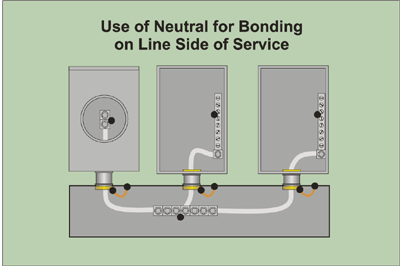
Use of neutral for bonding on line side of service
Section 250-94(1) permits the use of the grounded service conductor (may be the neutral) for grounding and bonding equipment on the line side of the service disconnecting means. This is also permitted by Section 250-142(a)(1). (Two other applications of this bonding are explored in later chapters of the IAEI Soares Book on Grounding.) Often, connecting the grounded service conductor to equipment such as meter bases, current transformer enclosures, wireways and auxiliary gutters is the most practical method of bonding these enclosures.
Usually, self-contained meter sockets and meter-main combination equipment are produced with the grounded conductor terminals or bus (often a neutral) bonded directly to the enclosure. The enclosure is then effectively bonded by the connection of the grounded circuit conductor to these terminals. No additional bonding conductor connection to the meter enclosure is required. Current from a ground fault to the meter or meter-main enclosure will return to the source by the grounded service conductor (may be a neutral) and, hopefully, will allow enough current to flow in the circuit to operate the overcurrent protection on the line side of the utility or other transformer.
In addition, meter enclosures installed on the load side of the service disconnecting means are permitted to be grounded (bonded) to the grounded service conductor provided that:
(a) Service ground-fault protection is not installed; and
(b) The meter enclosures are located near the service disconnecting means. (No distance is used to clarify what is meant by the word “near.”), and
(c) The size of the grounded circuit conductor is not smaller than the size specified in Table 250-122 for equipment grounding conductors. See Section 250-142(b) Exception No. 2.
Means of bonding at service equipment
The methods for bonding at service equipment are outlined in Section 250-94. These requirements for bonding are more restrictive at services than downstream from the service. The reason this is so important is service equipment and enclosures may be called upon to carry heavy fault currents in the event of a line-to-ground fault. The service conductors in these enclosures have only short-circuit protection provided by the overcurrent device on the line side of the utility transformer. Only overload protection is provided at the load end of the service conductor by the overcurrent device. This is one of the reasons the Code limits the length of service conductors inside of a building.
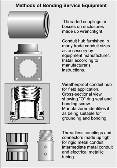
Bonding of these enclosures is to be done by one or more of the following methods from Section 250-94:
(1) Bonding to the grounded service conductor through the use of exothermic welding, listed pressure connectors such as lugs, listed clamps, or other listed means. These connections cannot depend solely upon solder.
(2) Threaded couplings and threaded bosses in a rigid or intermediate metal conduit system where the joints are made up wrench-tight. Threaded bosses include hubs that are either formed as a part of the enclosure or are supplied as an accessory and installed according to the manufacturer’s instructions.
(3) Threadless couplings and connectors are permitted where they are made up tight for rigid and intermediate metal conduit and electrical metallic tubing and metal-clad cables.
(4) Other approved devices such as bonding-type locknuts and bushings.
Bonding jumpers are required to be used around concentric or eccentric knockouts that are punched or otherwise formed so as to impair an adequate electrical path for ground-fault current. It is important to recognize that concentric and eccentric knockouts in enclosures such as panelboards, wireways and auxiliary gutters have not been investigated for their ability to carry fault current. Where any of these knockout rings remain at the conduit connection to the enclosure, they must always be bonded around to ensure an adequate fault-current path.
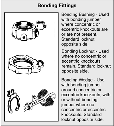
The Code states here that “Standard locknuts or bushings shall not be the sole means for the bonding required by this section.” This statement does not intend to prevent the use of “standard” locknuts and bushings, it is just that they cannot be relied upon as the sole means for the bonding that is required by this section. “Standard” locknuts are commonly used outside the enclosure on conduit that is bonded with a bonding bushing or bonding locknut inside the enclosure. Standard locknuts are used to make a good, reliable mechanical connection as required by Section 300-10.
Parallel bonding conductors
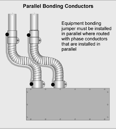
Section 250-102(c) requires that where service-entrance conductors are paralleled in two or more raceways or cables and the equipment bonding jumper is routed with the raceways or cables, the equipment bonding jumper must be run in parallel.
In this case again, the size of the bonding jumper for each raceway is based upon the size of the service-entrance conductor in the raceway by referring to Table 250-66.
Grounding and bonding of remote metering
As mentioned before, Section 250-92(a) requires all equipment containing service conductors to be bonded together and to the grounded service conductor. This includes remote (from the service equipment) meter cabinets and meter sockets.
Grounding and bonding of equipment such as meters, current transformer cabinets and raceways to the grounded service conductor at locations on the line side of and remote from the service disconnecting means increases safety.
This equipment should never be grounded only to a grounding electrode such as a ground rod. Figures 5-14 and 5-15 show why. If a ground-fault occurred at this line-side equipment, and it is not bonded as required, the only means for clearing a ground fault would be through the grounding electrodes and earth. Given the relatively high impedance and low current-carrying capacity of this path through the earth and high resistance of grounding electrodes such as rods, little current will flow in this path. This leaves the equipment enclosure(s) at a dangerous voltage above ground potential just waiting to shock or possibly electrocute a person or animal that may contact it. The voltage drop across this portion of the circuit can easily be calculated by using Ohms Law. (Resistance times the current gives the voltage.) There are many records of livestock being electrocuted while contacting electrical equipment that was improperly grounded. Sections 250-2 and 250-54 require that the earth not be used as the sole equipment grounding conductor or fault-current path.
The most practical method for grounding and bonding this line-side equipment is to bond the grounded service conductor to it. As can also be seen in Figures 5-14 and 5-15, a ground fault to the equipment will have a low impedance path back to the source through the grounded service conductor. This will allow a large current to flow in the circuit to cause the overcurrent protection on the line side of the transformer to clear the fault.
Supplementary grounding electrodes
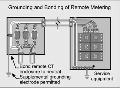
In accordance with Section 250-54, it is permissible to install a grounding electrode at the remote meter location shown in Figures 5-14 and 5-15 to supplement the grounded service conductor. This Code section refers specifically to grounding electrodes supplementing the equipment grounding conductors. Some electric utilities require a grounding electrode at meter equipment installed remote from service equipment such as on poles. The Code in Section 230-66 makes it clear that individual meter socket enclosures are not to be considered service equipment. The same is true for metering equipment installed in remote current-transformer enclosures. As mentioned earlier, it is critically important that these meter enclosures be properly bonded as they contain service conductors.
This additional grounding electrode will attempt to keep the equipment at the earth potential that exists at the meter location. In addition, the electrodes at the remote meter and at the service location are bonded together by the grounded service conductor installed between the metering and service equipment. This brings the installation into compliance with Section 250-58 which requires a common grounding electrode or where two or more electrodes are installed, they must be bonded together.
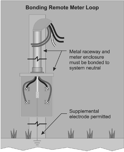
As previously stated, these grounding electrodes should never be used as the only means for grounding or bonding these enclosures or to carry fault current.
More extensive discussion of this subject is found in Chapter Six of the IAEI Soares Book on Grounding.
Bonding of multiple service disconnecting means
Installation of multiple services as permitted by Section 230-2(a) through (d) and installations of services that have multiple disconnecting means can take several forms. Additional services are permitted by Section 230-2 for:
(a) Fire pumps, emergency, legally required, standby, optional standby or parallel power production systems.
(b) By special permission, for multiple occupancy buildings where there is no available space for service equipment that is accessible to all occupants, or, for a single building or structure that is large enough to make two or more services necessary.
(c) Capacity requirements; where the service capacity requirements exceed 2,000 amperes at 600 volts or less, where load requirements of a single-phase installation is greater than the serving utility normally provides through a single service, or by special permission (related to capacity requirements).
(d) Different characteristics of the services such as different voltages, frequencies, or phases, or for different uses, such as for different rate schedules.
The basic rule for sizing of the equipment bonding jumper for bonding these various configurations is found in Section 250-102(c). This section requires that the bonding jumpers on the line side of each service the main bonding jumper be sized from Table 250-66. Also, the size of the bonding jumper for each raceway is based on the size of service-entrance conductors in each raceway. As discussed earlier, conductors larger than given in Table 250-66 are required for larger services. Since different sizes of service-entrance conductors may be installed at various locations, the minimum size of the equipment bonding conductor and main bonding jumper is based on the size of the service-entrance conductors at each location.
For example, the appropriate size of bonding jumper for the installation in Figure 5-16 with the assumed size of conductors is as follows: (all sizes copper)
| Service-Entrance Conductor | Bonding Jumper |
| a. 500 kcmil in service mast | 1/0 |
| b. 1000 kcmil in wireway | 2/0 |
| c. 300 kcmil to 300 ampere service | No. 2 |
| d. 3/0 to 200 ampere service | No. 4 |
| e. No. 2 to 125 ampere service | No. 8 |
A practical method for bonding the current transformer enclosure and wireway (sometimes referred to as a “hot gutter”) is to connect the grounded service conductor directly to the current transformer enclosure or wireway. This may be done by bolting a multi-barrel lug directly to the wireway and connecting the neutral or grounded service conductors to the lug. Be sure to remove any nonconductive paint or other coating that might insulate the connector from the enclosure.
As previously discussed, the grounded service conductor must also be extended to each service disconnecting means and be bonded to the enclosure.
Excerpted from Chapter 5 of the IAEI Soares Book on Grounding, 7th Edition





Find Us on Socials