Do you have a computer sitting on your desk? If so, chances are you have a surge protective device under your desk. As the use of products vulnerable to transient voltage surges and spikes continues to increase, the propagation of surge protection devices continues to increase. This article will focus on several types of surge protective devices, what they are, how they are tested, and the importance of markings, instructions and proper usage of the devices.
With the expanding surge protective devices industry comes a learning curve for code authorities, for electricians, for consumers and for the safety testing agencies. The code authorities begin to see an influx of different types of surge protective devices in the field and need to determine the proper usage and installation. Electricians need to know how to correctly install permanently connected surge protective devices. Consumers have to educate themselves as to which surge protective devices to purchase to meet their surge needs as well as how to install and use them safely. The safety testing agencies have to expand their knowledge base of surge protective devices to keep pace with the state of the art designs.
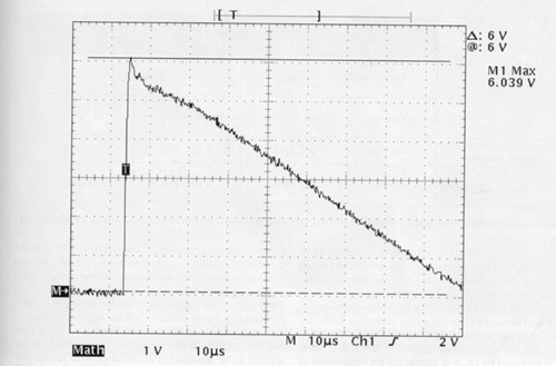
Figure 1.
What is a surge protective device and what does it do? A surge protection device is a device composed of any combination of linear or non-linear circuit elements intended for limiting surge voltages on equipment by diverting or limiting surge current. A surge protective device prevents continued flow of follow (power) current and is capable of repeating these functions.
Surge protective devices are available in many varieties, one of which is the transient voltage surge suppressor commonly referred to as TVSS. A TVSS may be permanently installed or may be of the cord-connected or direct plug-in style. Each type of TVSS is intended for use on the load side of the main service disconnect in circuits not exceeding 600 volts rms. The main service disconnect is considered to be the first overcurrent protective device between the distribution transformer secondary and the service entrance.
The basic safety standard used to test TVSS is UL 1449, the Standard for Safety for Transient Voltage Surge Suppressors. UL 1449 addresses construction items such as enclosure requirements, minimum wiring size for internal wiring as well as field wiring, acceptable spacings between circuits of opposite polarity or to metal walls of an enclosure, proper grounding means, and suitability of mounting to name a few. UL 1449 also contains testing, marking and installation instruction requirements.
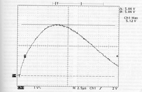
Figure 2.
As well as containing the basic safety tests known to many UL electrical safety standards such as Leakage Current, Normal Temperature, Dielectric Voltage Withstand, etc., UL 1449 also contains a Measured Limiting Voltage Test. The measured limiting voltage is the maximum magnitude of voltage, measured at the output (leads, terminals, or receptacle contacts) of the TVSS during application of a test impulse of specified waveshape and amplitude. The Measured Limiting Voltage Test includes a duty cycle to determine that the surge suppression components can repeatedly limit the transient voltage surge test waveform without degradation.
During the Measured Limiting Voltage Test, it is verified that the average measured limiting voltages do not exceed the suppressed voltage rating marked on the product when subjected to a standard 1.2 by 50 microsecond (Figure 1), 8 by 20 microsecond (Figure 2) combination standard test waveform with the peak values shown in Figure 3. A component that is being subjected to the Measured Limiting Voltage Test is shown in Figure 4.
Within recent years UL 1449 was revised to include Abnormal Overvoltage Tests for TVSS devices. These abnormal overvoltage tests were added because surge protective devices may be located in areas with very high transient currents and/or long or short term abnormal overvoltages for which they may not be designed. When surge protective devices are exposed to abnormally high surge currents or to abnormal overvoltages, the surge protective component attempts to limit the abnormal by conducting or turning on. Since the surge protective components may not be designed for this purpose, means should be taken to make sure the TVSS can withstand the abnormal overvoltages or high surge currents without risk of fire or electrical shock.
The Surge Current Test in UL 1449 subjects TVSS devices to high transient currents and the Abnormal Overvoltage Tests in UL 1449 subject TVSS to abnormal power overvoltages. The Full Phase Voltage High Current Abnormal Overvoltage Test anticipates essentially a double overvoltage with the availability of follow current ranging from 200 amperes to 25,000 amperes or even higher fault current up to 200,000 amperes if the manufacturer requests. The Limited Current Abnormal Overvoltage Test anticipates the same double overvoltage but with a limited current ranging from 5 amperes to 0.125 amperes. Each test causes the TVSS to react differently. High current is the fast acting overvoltage whereas the limited current is a slow burn situation. Products manufactured bearing the UL Mark must pass the Surge Current and the Abnormal Overvoltage Tests of UL 1449 without increased risk of fire or electric shock.
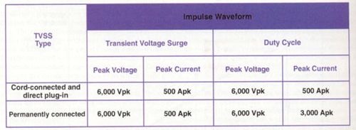
Figure 3.
With TVSS devices it is important to read and follow all installation/operating instructions provided with the unit. At a minimum, the instruction manual for a permanently installed TVSS is required to contain instructions for installation including the minimum and maximum wire length and gauge sizes, the ampacity of the circuit the device is intended for use on, and the internal wiring methods showing location and routing. Instructions for mounting as well as an explanation of the purpose and function of any indicator features employed on the TVSS such as lights, audio indicators or the like should also be provided.
It is also important to understand and adhere to markings on TVSS devices. Permanently installed TVSS are required to be marked with the electrical ratings including the operating voltage rating, the ac power frequency and for certain devices, the load current rating. Permanently installed TVSS have a connection diagram and some TVSS devices may indicate a fault current rating as well as a requirement for the use of an externally connected fuse or breaker. When this marking is required by UL, it is important for consumers as well as code authorities to understand this marking means the TVSS device was tested at the specified fault current with the fuse or breaker installed during the Full Phase Voltage High Current Abnormal Overvoltage Test and the fuse or breaker operated during the test. Therefore, it is very important to make sure this marking is not ignored during installation of the TVSS.
Another marking of importance is the Suppressed Voltage Rating. The suppressed voltage rating is the rating or ratings selected by the manufacturer from the range of 330 volts peak to 6000 volts peak based on the measured limiting voltage determined during the Measured Limiting Voltage Test. 330 volts peak is the lowest and 6000 volts peak is the highest rating that may be marked on the TVSS based on the let-through voltage measured during the Measured Limiting Voltage Test. It is important to understand that a 330 volts peak suppressed voltage rating is not necessarily considered the “”best”” rating and higher peak voltage ratings are not necessarily considered “”worse”” ratings. TVSS devices should be chosen based on analysis of the transient problems that the TVSS is being used for and not only for the lowest suppressed voltage rating marked on the device. Many times a transient problem on a power system may require a combination of surge protective devices installed at critical locations within the power system.
Another type of surge device is the surge arrester. Low voltage surge arresters rated up to 999 volts ac are intended to afford protection against surge related damage to secondary distribution wiring systems and/or to downstream equipment. Surge arresters rated 1000 volts ac or higher are intended to afford protection against surge related damage to wiring systems and/or downstream equipment. Surge arresters are for use on alternating current power circuits and are intended to be installed in accordance with Article 280 of the National Electrical Code.
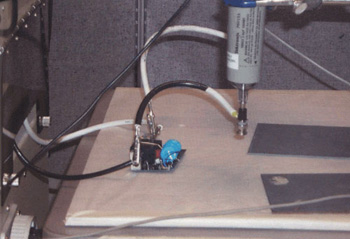
Figure 4. Device under test
The basic standard used to investigate metal oxide surge arresters is ANSI/IEEE C62.11, Standard for Metal-Oxide Surge Arresters for AC Power Circuits. Other types of surge arresters are investigated using IEEE C62.1-1989, Standard for Gapped Silicon-Carbide Surge Arresters for AC Power Circuits.
The types of low voltage surge arresters include secondary, metal-oxide, valve and distribution light duty. The types of higher voltage surge arresters include station, intermediate, distribution (heavy, normal and light duty).
Surge arresters are subjected to aging tests as well as surge tests. With surge arresters as with TVSS devices is it important to read and follow all installation instructions and markings.
Surge arresters are intended for installation on the line side of the main overcurrent protection. It is important to understand that a surge arrester should not be installed on the load side of the main overcurrent protective device unless it has also been investigated as a TVSS. The reason for this is that the surge arrester has not been subjected to the Abnormal Overvoltage Tests of UL 1449 which, as noted above, are critical tests for usage of a surge protective device on the load side of the main overcurrent protective device.
The surge protective device which may be the type that is most widely recognized by consumers is the cord-connected or direct plug-in TVSS device that is typically found under your desk or behind your television or stereo. These TVSS devices are also referred to as relocatable power taps, power taps or current taps. These taps with internal surge components provide surge protection to multiple outlets, phone jacks, or cable jacks so that vulnerable products such as your personal computer, printer, scanner, fax machine, phone, cable connection etc. can be provided with surge protection from one convenient location.
Relocatable power taps or current taps are intended to be plugged directly into a branch circuit receptacle of the proper plug configuration. Power taps and current taps are not intended to be plugged into an extension cord or into another power tap or current tap nor have they been investigated for this purpose. All power taps and current taps with a ground pin are intended to be plugged into a properly grounded branch circuit receptacle and the ground pin should never be removed. In addition, the cords of power taps are not intended to be used as mounting means nor should the cord be routed under or around desk walls or through openings in doors, windows, ceilings or the like.
In summary, the propagation of surge protection devices will continue to increase. This article has provided some insight into types of surge protective devices, some of the safety tests they must undergo as well as installation locations. More information concerning surge protective devices can be found in the UL General Information for Electrical Equipment Directory or in the UL Electrical Equipment Construction Directory under the categories Transient Voltage Surge Suppressors (XUHT), Surge Arresters (OWHX), Surge Arresters, 1000 Volts and Higher (VZQK), Relocatable Power Taps (XBYS) or Current Taps (EMDV).
If you have questions concerning this article or surge protective devices contact Deborah Jennings-Conner at 919-549-1603 or Deborah.Jennings-Conner@ us.ul.com.