Most properties today, whether residential, commercial, or industrial, include at least one building or structure on that property. Often there are multiple buildings on a single property. Some include buildings that are each supplied by its own utility service and others have an electrical service at one point and deliver electrical power to the other buildings or structures by feeder(s) or by branch circuit(s). This article takes a closer look at the grounding and bonding requirements and methods for separate buildings or structures supplied from other than a service.
When a building is constructed it requires a solid foundation that connects the building to the earth. Grounding for electrical systems and equipment serves as the foundation for the electrical system or service. Whether a building or structure on a property is supplied by a service or by a feeder, a grounding electrode is generally always required. The electrode provides two important electrical functions. First, where electrical equipment and systems are connected to the earth through the grounding electrode or grounding electrode system, differences of potential between the earth and those conductive elements are minimized. This connection to the grounding electrode reduces shock hazards and maintains the same potential during normal operation. During abnormal events, such as ground faults and short circuits, the connection to ground works to minimize potential differences during the duration of the overcurrent device clearing time. The second important benefit of the grounding electrode at the separate building or structure is limiting voltages imposed by lightning, line surges, or unintentional contact with higher voltages.
Grounding electrical systems also provides benefits of stabilizing voltage to ground during normal system operation. It should be noted that the grounding electrode and grounding electrode conductor have little or no effect in the operation of overcurrent protective devices. The earth or grounding does not provide an effective fault current path.
There are two important definitions one must fully understand to grasp the performance concepts and criteria for grounding and bonding. Let’s take a look at these two definitions and establish the difference between the two terms.
Grounded.Connected to earth or to some conducting body that serves in place of the earth.
Bonding (Bonded).The permanent joining of metallic parts to form an electrically conductive path that ensures electrical continuity and the capacity to conduct safely any current likely to be imposed.1
Note: There are many derivatives of these two terms used in a variety of ways throughout the NEC. Perhaps this is one reason for some misunderstandings and misapplication of the grounding and bonding rules. It is important to have a complete understanding of the performance required from each of the two terms grounding and bonding.
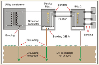
Figure 1. Grounding and bonding functions
Clearly two separate performance functions are described in the definitions of these terms. To simplify their meaning, think of ground as earth. When an object or conductor is grounded, it, by definition, is connected to the earth. When objects are bonded together, the joining must be done in a manner that creates a path between them with the capacity to conduct safely any current (fault current or normal current) likely to be imposed (see figure 1). The tripping of overcurrent devices is directly related to the bonding, and not the grounding, function as stated by the definition and in the performance language of 250.4(A) and 250.4(B) which describes the purpose of each function.
Grounding for services and separately derived systems is required, and the grounding electrode connection (grounding point) is generally located at the service or source of a separately derived system as required by the NEC. The non-current-carrying conductive materials enclosing electrical conductors or equipment, or forming part of such equipment, are required to be connected together (bonded) and connected to the supply source grounding point in a manner that establishes an effective fault current path [NEC 250.4(A)(3)]. Generally as these non-current-carrying parts are bonded together, they are also simultaneously grounded because of the connection to earth at the grounding point for the service or separately derived system. Basically grounding and bonding are two separate performance functions that generally happen simultaneously, and both must be ensured for safety. It is important to understand the performance required for each of these functions to accurately apply the rules of the NEC to installations and systems in the field.
Grounding Electrode Required
When applying the grounding and bonding rules for multiple buildings, one must verify that both performance functions are met and are in concert with the requirements of the NEC. As the feeder arrives at the separate building or structure, several NEC rules must be applied. Rules for separate structure disconnecting means and their locations must be applied. Generally this is also where the initial or first grounding and bonding connections will be made. The NEC requires that a building or structure supplied by a feeder or branch circuit must have a grounding connection through the available grounding electrode or grounding electrode system at that building or structure. Basically this required grounding electrode is the same for this building or structure whether a service or a feeder supplies it. It must have a grounding electrode(s). The grounding electrode system must be made up of the specified electrodes in Part III of Article 250.
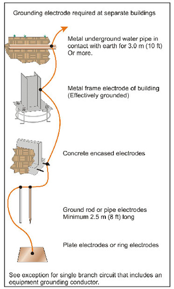
Figure 2. A grounding electrode(s) is generally required at separate buildings or structures
Where there are no electrodes as specifically described in 250.52(A)(1) through (A)(6), one of the electrodes described in 250.52(A)(4) through (A)(7) is required to be installed. One exception relaxes the requirement for the grounding electrode at a separate structure; the electrode is not required where the structure is supplied by one branch circuit that includes an equipment grounding conductor for grounding the conductive non-current-carrying metal parts of all equipment in the structure. So, as can be seen, the grounding electrode at a separate building is generally required [NEC 250.32(A)].
Two methods of grounding and bonding connections at separate buildings or structures are provided in the NEC. One method is required where the feeder or branch circuit includes or provides an equipment grounding conductor in addition to any grounded system conductor as part of the feeder or branch circuit. The second (alternative) method is where the feeder or branch circuit does not provide an equipment grounding conductor where it supplies the separate building or structure. Keep in mind the grounding electrode is required generally at the separate building regardless of whether or not an equipment grounding conductor is provided, unless qualifying under the provision of the exception discussed previously.
Where Equipment Grounding Conductor Is Provided
Feeders are generally required to include an equipment grounding conductor [NEC 215.6]. It is more common in wiring installations today to distribute feeders that include equipment grounding conductors. In recent NEC cycles there has been an increased emphasis on migrating away from using the grounded conductors for grounding purposes on the load side of a service or separately derived system. There are general rules in the NEC that prohibit grounding connections to the grounded (often neutral) conductors on the load side of the service or separately derived system grounding point [NEC 250.24(A)(5); 250.142(B); 250.32(B)(1)]. The primary reason is to keep normal (neutral) currents from flowing over other electrically conductive metallic paths back to the source. Keep in mind that current (normal or fault current) will attempt to follow any and all paths to return to the source and will divide over those paths inversely proportional to the impedance of each path.
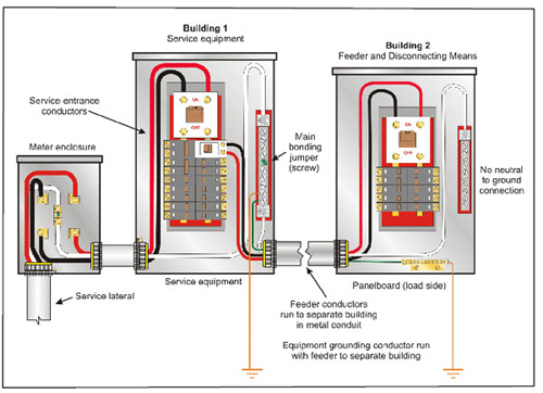
Figure 3. Grounding and bonding at separate building or structure using the method described in Section 250.32(B)(1) with the equipment grounding conductor
Where the feeder supplies a separate building or structure and includes an equipment grounding conductor, the equipment grounding conductor is required to be connected (bonded) to the structure disconnecting means. The size of the equipment grounding conductor (of the wire type) must meet the minimum sizes specified in 250.122 based on the overcurrent protective device size for the feeder or branch circuit supplying the building or structure (see figure 3).
The required grounding electrode conductor must also be connected to the disconnecting means. The minimum size of the grounding electrode conductor must be in accordance with 250.66 [250.32(E)]. The grounded (often the neutral) conductor must terminate on a grounded conductor terminal bar in the disconnect enclosure that is insulated (isolated) from the enclosure. This keeps any neutral conductor current from contact with metal parts at that point on the system. Neutral current should return to the service equipment over one path, the neutral in this case, which is the performance goal. In fault conditions, the equipment grounding conductor serves as the protective bonding circuit to provide an effective bonding connection back to the source that will facilitate the operation of the overcurrent device and open the faulted condition. The grounding electrode under these fault conditions serves to keep the metal equipment and other conductive materials at the same (earth) potential during the time duration of the event.
Where Equipment Grounding Conductor Is Not Provided
The second method for grounding and bonding at a separate building or structure is allowed where the feeder does not provide an equipment grounding conductor, but does include a system grounded (often a neutral) conductor. This second method is a bit more difficult to utilize because there are more specific restrictions that must be considered and adhered to. Three conditions must exist before one may use the grounded conductor for grounding purposes at a separate building or structure.
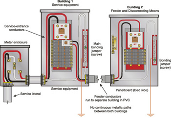
Figure 4. Grounding and bonding at separate buildings or structures using the grounded conductor by the method specified in Section 250.32(B)(2)
The first condition is that an equipment grounding conductor, of any form specified in 250.118, is not provided or run with the supply to the structure. This means that only the phase conductor(s) and the system grounded conductor either as direct burial, in nonmetallic conduit underground, or as overhead conductors are included. The key is that no equipment grounding conductor is included.
The second condition is that no continuous metallic paths exist or are otherwise present, and that are bonded to the grounding system in both buildings. Examples of continuous metallic paths could be metal water piping, building steel, metallic conduit, cable shields, metal ducts, and so forth.
The last condition that must be met prior to utilizing this method is that no equipment ground-fault protection is installed on the supply service or feeder, as neutral-to-ground connections on the load side of this equipment can nullify or desensitize the equipment protection.
If all of these conditions are met, then the grounded conductor of the feeder or branch circuit is permitted to be used for grounding and bonding the electrical equipment. It must be connected to the structure disconnecting means enclosure to which the required grounding electrode conductor is also connected. The minimum size of the grounded conductor of the feeder or branch– circuit must satisfy two minimum sizing requirements. First, it must be adequate to carry the maximum load on the grounded (often a neutral) conductor as specified in 220.22. Second, it also must not be smaller than the required equipment grounding conductor for the feeder or branch circuit using 250.122, based on the size of fuse or circuit breaker ahead of it.
In addition to being a normal current-carrying conductor, the grounded conductor keeps the electrical equipment and other conductive materials at ground (earth) potential. During both normal and fault conditions, the grounded conductor serves as the required effective ground-fault current path to facilitate the operation of the feeder or branch-circuit overcurrent devices.
Separate Building or Structure Disconnecting Means
The NEC includes requirements for a disconnecting means where a feeder(s) or branch circuit(s) supplies a separate building [NEC 225.31]. This disconnecting means must be located either outside or inside the building served and must be readily accessible nearest the point of entrance of the conductors, or be located outside the building. These requirements, for the most part, parallel the requirements for locations of service disconnects as specified in Article 230.
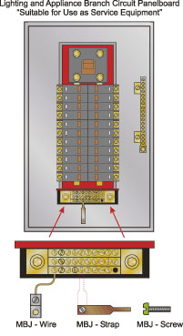
Figure 5. Equipment identified as “suitable for use as service equipment” generally includes grounding and bonding capabilities as shown in the graphic and is also clearly identified for this use
The required disconnect for the feeder or branch circuit supplying the separate building or structure generally must also be suitable for use as service equipment [NEC 225.36]. Disconnecting means and equipment identified as “”suitable for use as service equipment”” are constructed to include the features and provisions for grounding and bonding. Generally, this means that a “”main bonding jumper”” in the form of a screw, strap, bus, or conductor is provided for connection between the grounded conductor and the enclosure. This equipment allows for proper grounding and bonding connections at the separate building or structure for either of the two grounding and bonding methods provided in 250.32(B)(1) or (2) [see figure 5].
Keep in mind that this disconnecting means is required generally, and it must be suitable for use as service equipment. The grounding electrode is required, and it must be connected to the disconnecting means enclosure just as it is at the service equipment on the upstream side of the separate building or structure. The difference is how the connection of the grounded (often a neutral) conductor at this disconnecting means is made and is directly related to the two alternate methods provided in 250.32(B). Remember, it is important to keep current on its intended path during normal operation.
Summary
It is important to understand the different performance criteria between grounding and bonding. Specific performance requirements are now included as rules in Article 250 and help in the understanding of the purpose of the prescriptive requirements. Three definitions of performance-based terms are provided in 250.2 and assist users in increasing the understandability of the reasons and purposes of the functions of grounding compared to bonding. A properly grounded and bonded electrical system and installation provide both functions as a seamless and simultaneous protection system. Generally if objects are effectively bonded, they are usually also grounded effectively. If objects are only grounded by definition, they may not be effectively bonded to facilitate overcurrent device operation. Remember the earth is not permitted as an equipment grounding conductor and must not be used as an effective ground-fault current path. Visit the definitions in Article 100 and establish a solid understanding of the meaning of the grounding and bonding terms and words. It is important for accurate and proper application of rules to installations and systems. This article is based on the requirements contained in the 2002 edition of the NEC. Always consult the authority having jurisdiction for any local electrical requirements or ordinances in your area.
1National Electrical Code, 2002, Article 100, Definitions. National Fire Protection Association, Inc., Quincy, MA 02269.