
Photo 1. 400-amp load center, 300-amp main. Internal supply side and load side PV connections are possible.
The Basic Requirement
This section of Code was written to address a general condition where any panelboard busbar or conductor might be fed by multiple sources of power that are connected to the busbar or conductor through overcurrent devices. Although the 2008 NEC 690.64(B) appears to restrict the connection point, in fact nearly any point on a load-side circuit (inside a panelboard or on the conductors of a feeder or branch circuit) may, and has, served as a connection point for either a PV inverter or for an additional load circuit. Of course, there are numerous restrictions and requirements on making such connections, but in general, all of the load-side wiring is up for grabs and the connections and circuits must be protected.
There are no restrictions in this code requirement as to the particulars of any specific installation. There are no restrictions on where the multiple power sources might be connected on the busbar or conductor nor are there any limits on the number of overcurrent devices. There are no restrictions on the loads connected to the busbar or conductor either in terms of their connection point or the rating of the overcurrent device and, in fact, loads are not specifically addressed in the section. When applying this requirement, no assumptions should be made as to the configuration of the circuit with respect the location of connections (taps) and the number, magnitude and locations of any sources or loads. Some people even feel that the code requirement was written to “Protect people from doing harm—in the future.”

Photo 2. Load side connection. Conductor size to the PV inverter too small to meet 690.64(B) requirements.
This is the manner in which many code requirements are formulated. The requirement is written in general terms and then the general requirement is modified by exceptions (restrictions or allowances) or additions to the requirement.
From an engineering point, the basic requirement is sound. A conductor or busbar will be prevented from being overloaded if the rating of that busbar or the ampacity of that conductor is greater than or equal to the sum of the ratings of all overcurrent devices supplying it [see 690.64(B)(2) in2005 NEC]. Note that the requirement refers only to theratingof thesupplyovercurrent devices, not to any calculated currents and it does not refer to any load overcurrent devices.
Because dwelling unit load centers are usually not fully loaded and the Chapter 2 load calculations usually result in light panel loadings, the 690.64(B) requirement up to the2008 NECallowed a dwelling exception to the extent that the sum of the ratings of the supply overcurrent devices could exceed the rating of the busbar or conductor up to 120%. This allowance for dwelling units would allow up to 20 amps of backfed PV breaker to be installed on a 100-amp rated panel that had a 100-amp main breaker. By calculation:
- 120% of 100 amp busbar = 120 amps.
- 120 amps allowance -100 amp main = 20 amps for a backfed PV breaker.
- 20 (PV breaker) + 100 (main breaker) = 120 amps sum of supply breakers which is less thanor equal to 120% of busbar rating which is120% of 100 amps = 120 amps.
In a similar manner, a 200-amp rated panel with a 200-amp main breaker would be allowed to have up to a 40-amp backfed PV breaker.

Photo 3. Load-side connection on output main breaker. Conductors to PV disconnect/overcurrent protection should be as large as the main output conductors.
In the 2005 and earlier editions of this section, non-dwelling, commercial PV installations did not have the 120% exception and the basic requirement applied. That meant that in a commercial installation where a main breaker in a load center was rated the same as the busbar, no PV could be connected. Also when a conductor ampacity was the same as the OCPD for that conductor, no load-side connection for PV could be made. Supply-side connections, 690.64(A) / 705.12(A), were usually required.
In at least five code cycles, various changes and modifications have been proposed to change the basic requirement and wording. CMP-13 and now CMP-4 (2011 and subsequent editions of the Code) have ruled that theonlyway to protect this general busbar or conductor, that has no restrictions, is that the busbar or conductor must have a rating or an ampacity equal to or greater than the sum of the ratings of all overcurrent devices supplying that busbar or conductor.
Various Other Connections Can Be Safe
As the time progresses, we have seen various wiring configurations for that general, unrestricted, busbar or conductor that might allow exceptions to the basic requirements. These wiring configurations are discussed among inspectors, electricians, conductor and panelboard manufacturers and, as they are vetted to be safe, proposals are made to change theNEC. These are in the form of exceptions or modifications to the basic requirements.
This process is not unique to 690.64(B)(2) / 705.12(D)(2) and similar actions have been taken throughout the NEC.
With respect to 690.64(B)(2) / 705.12(D)(2), it has long been recognized that if there are only two supply overcurrent devices and that they are opposite ends of the busbar or conductor, then even if unrestricted loads or load taps are added between the two supply overcurrent devices, there is nowhere on the conductor or busbar where the currents may exceed the rating of the largest overcurrent device.
An internal CMP revision of 690.64(B) for the 2008 NEC recognizes this fact and requires that in a panelboard, if the two supply overcurrent devices are at opposite ends of the busbar (and possibly a conductor), the sum of the ratings of the busbar or conductor may exceed the current rating of the busbar by 20%. The assumption is made that actual load on the panel will not exceed the panel or conductor rating in most residential and commercial locations. Unfortunately, actual experience dictates that plug loads are essentially unrestricted and unmonitored and may result is loads higher than calculated by the installing electrician. But even if the actual loads on a busbar or conductor exceed numerically the rating of the busbar or the ampacity of the conductor, with the supply overcurrent devices at opposite ends, there is no place on that busbar or conductor where the currents will or can exceed the rating. This revision allows the 120% exception to be applied to both dwelling units and non-dwelling installations if the overcurrent device location requirement can be met.
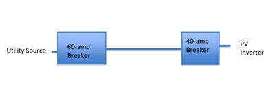
Figure 1. The conductor has a 60-amp breaker at the utility feed end and it has a 40-amp backfed breaker at the PV inverter end. If the conductor is not tapped for loads or other sources, then the highest current that it could ever see under any normal or fault condition is 60 amps, the rating of the highest connected supply overcurrent.
Is the Code Too Conservative?
The information in the following paragraph is technical in nature and may be subject to further investigation. It gives some indication that theCodemay not be as overly conservative as many feel it is.
While this situation of connecting supply overcurrent devices at opposite ends may be safe for restricted conductors, it may not be suitable for busbars in panelboards (load centers), even though this allowance is in the 2008 and 2011NEC. Panelboards are subject to busbar current limitations and are also subject to thermal limitations due to the heating associated with the thermal trip elements in the common thermal/magnetic molded-case circuit breakers. For example, a 100-amp, 120/240V panelboard is tested during the listing process with a 100-amp main breaker (line 1 and line 2) and two 100-amp load breakers (one per phase) mounted directly below the main breaker. The ambient temperature is raised to 45 degrees Celsius, the input and output currents are set at 100 amps, the temperature is allowed to stabilize, and the panel must pass this test with no deformation of any parts that would result in external damages. The internal thermal load is related to the heat produced by 100 amps passing through four circuit breaker trip elements. This would be a thermal load equivalent to 400 amps. If we add a double-pole backfed PV breaker, for example 20 amps, at the bottom of the panel, and if the loads on the panel were increased to 120 amps (per phase), no breakers would trip, no busbars would be overloaded, but the thermal load in the panel would be that associated with 480 amps, not the 400 amps for which the panel was designed and listed. Panel manufacturers have stated that these panels may not be able to pass UL listing tests with those excessive thermal loads. Plastic insulators could deform and arcs and sparks could result.
How likely is it that increased loads would occur at the same time as high daytime PV outputs? No one knows, but the possibility exists and some inspectors report warm/hot load centers (without PV input) that may be operating already close to the rating of the main breaker. An extra copier, fax machine or large screen TV might tip the balance.
Code Requirements Do Not Always Make Sense
Consider Figure 1: The conductor has a 60-amp breaker at the utility feed end and it has a 40-amp backfed breaker at the PV inverter end. If that conductor is not tapped for loads or other sources, then the highest current that it could ever see under any normal or fault condition is 60 amps, the rating of the highest connected supply overcurrent. However, 690.64(B) / 705.12(D) require the ampacity of the cable to be not less than 120% of the sum of the ratings of the supply overcurrent devices. As a calculation:
- 60 + 40 must be less than or equal to 120% of the ampacity of the conductor.
- 60+40 <= 1.2 x A 100 <=1.2A
A >= 100/1.2 = 83 amps the required cable ampacity
A proposal was made for the2011NECthat would apply to end-fed conductors that have a restriction (marking) that they not be tapped for either loads or supplies. If this proposal were accepted — it was rejected — then the conductor would need an ampacity only as high as the highest rating of one of the connected supply overcurrent devices.
In previous Code cycles, labels and placards that say, “Add no loads” have been proposed. Those proposals have been rejected. Proposals for dedicated ac inverter combining panels with no spaces for loads have been proposed. They have been rejected. Covering empty breaker positions with metal guards have been proposed — rejected. Marking conduits, “PV output circuits, multiple source, do not tap”— rejected.
Exceptions were proposed to 690.64(B) / 705.12(D) to allow more flexible installations. These exceptions place restrictions or allowances on the general conditions of an unrestricted busbar or conductor. The restrictions keep the various installations safe.
For example, the 2008 NEC 690.64(B)(2) requirement says to add the ratings of all breakers supplying current to the panel. This would include the main plus all backfed PV breakers. Assume that it is desired to combine the outputs of two inverters in a dedicated PV ac combining panel with two 40-A breakers. An 80-A main breaker would normally be needed. The sum of all breakers would be 160 amps, necessitating a 200-panel to meet 690.64(B)(2) / 705.12(D)(2). However, if an exception (restriction) were added that prevented any loads from being added to the panel, then the maximum current that the busbar would ever see would be limited to the sum of the PV breakers or the main breaker, if larger. The panel could then be rated at 80-A or 100-A — still safe, and less costly.
The AHJ Has the Final Say
An AHJ may certainly look at a specific installation consisting of a specific set of supply breakers, loads, and locations of the same and evaluate the ampacity requirements of the conductors or busbar. If an alternate methods and materials (AMM) approval is issued to allow a deviation from the wording of theNEC, then the AMM approval might also include instructions to the installer to modify the installation in a way to minimize the possibility of future changes to the installation that might violate the exceptions (restrictions). For example, a “No Loads Allowed” placard might be required on an ac PV inverter combining panel when an AMM approval has allowed the rating of the panel as either the main breaker rating or the sum of the PV breakers, whichever is greater. Another example (proposed for the2011 NEC but not accepted) is to allow a conductor fed from supply breakers at each end, to have an ampacity of the greater breaker rating, not the sum of the breakers, when the conductor is marked, “Multiple Power Sources — Do Not Tap” every ten feet where the conductor is accessible and inside any connected distribution equipment.
2014
Well-substantiated proposals will again be submitted for the 2014NECto allow some exceptions to the basic requirements in 705.12(D). Hopefully, CMP-4 will carefully address these proposals and see that PV installations can be safe, durable and cost effective without overly restricting the installations.
Summary
In summary, 690.64(B)(2) / 705.12(D)(2) is written as an unrestricted requirement for sizing conductors and busbars fed from multiple sources. The conductor or busbar is protected for any combination of loads and/or multiple sources and locations of loads or sources connected to the busbar or conductor. It would appear that the existingCodemight be overly restrictive.
For Additional Information
The US Department of Energy funding for providing inspectors and the PV industry with telephone and e-mail support from the author was terminated on March 1, 2011. Answers to your questions may be delayed or not answered at all depending on future funding. Consultation services are available on a contracted basis. E-mail: <ahref=”mailto:jwiles@nmsu.edu”>jwiles@nmsu.eduPhone: 575-646-6105
See the web site below for a schedule of presentations on PV and theCode.
The Southwest Technology Development Institute web site maintains a PV Systems Inspector/Installer Checklist and all copies of the previous “Perspectives on PV” articles for easy downloading. A color copy of the latest version (1.91) of the 150-page,Photovoltaic Power Systems and the 2005 National Electrical Code: Suggested Practices, written by the author, may be downloaded from this web site: <ahref=”http: www.nmsu.edu=”” ~tdi=”” photovoltaics=”” codes-stds=”” codes-stds.html”=””>http://www.nmsu.edu/~tdi/Photovoltaics/Codes-Stds/Codes-Stds.html
And yes, it may be updated to the 2008 and 2011 Codes sometime this year.