One common way of minimizing possibilities of electrical wiring and equipment becoming an ignition source in hazardous (classified) locations is to locate the equipment and wiring outside of the hazardous (classified) location wherever possible. This is always a practical approach and a good exercise of ingenuity, although it is not always possible. Often equipment and wiring installations have to be located within hazardous (classified) locations, and safe installations require a thorough understanding of more restrictive wiring rules.
The general requirements of Chapters 1 through 4 apply to these installations unless modified or amended by the specific applicable rules in Chapter 5. A failure in the wiring system in any location is never desirable, but the risk of explosion that exists in hazardous (classified) locations provides urgent reasons to ensure that the minimum requirements of the Code are met.
Some of the issues covered in NEC 500.8, Equipment, apply to protection techniques for utilization equipment and devices; other requirements are applicable to wiring. Based on the definition of equipment located in Article 100, almost every component of an electrical circuit and every piece of utilization equipment connected to that circuit would qualify as equipment. In general, 500.8 limits the operating temperature of the circuit and equipment, provides for marking requirements, and establishes the threading requirements for conduit, fittings, and threaded entries into equipment. Within those threading requirements are provisions for adapting from National (American) Standard Pipe Taper (NPT) to metric threading. These general requirements apply to the wiring in Class I, Class II, and Class III locations under the Division system. Similar requirements are covered in 505.9 for Class I, Zone installations and in 506.9 for dust Zone installations.
Wiring Outside the Classified Area
Article 501 does not specifically address or restrict wiring requirements outside of classified locations. However, those involved with electrical installations should be aware that many occupancy standards and recommended practices do limit wiring methods or modify general wiring requirements in unclassified locations near classified spaces. In some situations, wiring and/or equipment outside the classified space could provide ignition of a flammable atmosphere by releasing ignition-capable particles that could communicate to the classified spaces. Since the details of these possible hazards vary greatly from process to process, and from material to material, and from electrical system to electrical system, specific occupancy standards address the issues and requirements rather than their being addressed in the wiring requirements in Part II of Article 501. Examples can be found in Section .7 (i.e., 511.7, 513.7, etc.) of Articles 511 through 516. Additional examples can be found in documents such as NFPA 50B, Liquefied Hydrogen Systems at Consumer Sites, which prohibits the installation of hydrogen systems beneath electric power lines.
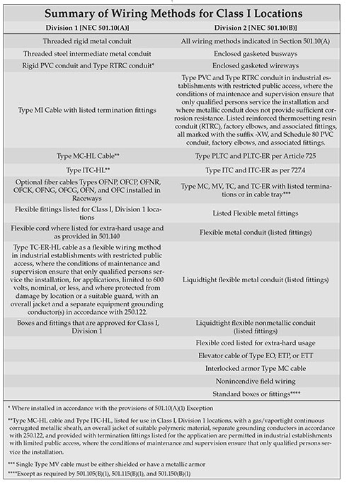
Wiring requirements within Class I hazardous areas using Division system are found in Part II of Article 501. The recognized acceptable wiring methods are included in 501.10, with (A) addressing Division 1 locations, and (B) addressing Division 2 locations. Wiring requirements for the Class I, Zone system are found in 505.15.
Division System
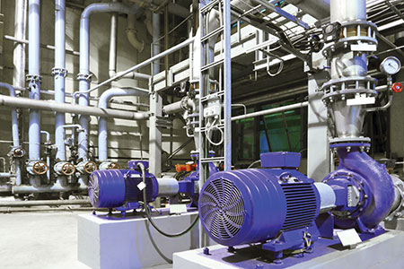
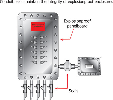
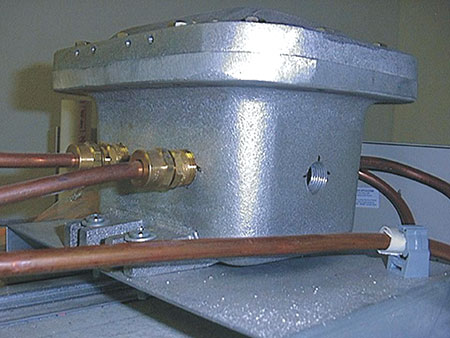
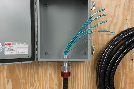
Since Class I, Division 1 locations are expected to include ignitible concentrations of flammable gases, flammable liquid-produced vapors, or combustible liquid-produced vapors under normal operating conditions, the wiring requirements are more restrictive (see photo 1). Wiring methods permitted in these spaces include threaded rigid metal conduit and threaded steel intermediate metal conduit. Rigid Type PVC and Type RTRC conduits may be permitted under certain conditions where placed underground and encased in concrete. Type MI cable, and within specific industrial applications, listed Types MC-HL and ITC-HL cable systems are permitted. With these wiring methods, it is anticipated that ground faults and/or short circuits could take place within them and they would be able to contain those faults. Since ignitible concentrations are expected under normal conditions, it is also anticipated that these faults could result in an explosion within the wiring method that must be contained. In many cases, these types of wiring methods are connected to explosionproof enclosures and, consequently, become an extension of that enclosure (see figure 1).
In addition to the more robust wiring methods described above, where the wiring is intrinsically safe, any wiring method permitted for unclassified locations and any wiring method or cabling system recognized in Chapters 7 or 8 of the NEC is permitted [NEC, 504.20]. All of these systems provide acceptable protection of the electrical circuits and containment of possible faults to prevent ignition of surrounding ignitible atmospheres.
Wiring Methods for Class I, Division 1 Locations
Rigid Metal Conduit & Intermediate Metal Conduit
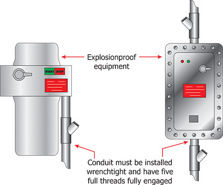
Wiring methods permitted in Class I, Division 1 locations are identified in Sections 501.10(A) and include threaded rigid metal or threaded steel intermediate conduit. The conduit must be threaded with a National (American) Standard Pipe Taper (NPT) thread that provides a 1 in 16 (¾ inch) taper per foot. It must be made up wrenchtight and have five threads fully engaged where connected to explosionproof enclosures. Some listed explosionproof enclosures may require only 4½ threads fully engaged because of the factory provided NPT entries; these are recognized by exception to the general requirement. The requirement to be wrenchtight is one of the most important installation rules for conduit installed as a wiring method for hazardous (classified) locations. Installers and inspectors must assure that this requirement is met. In many cases, the integrity of explosionproof enclosures depends on this requirement being satisfied [see figure 2].
The Code requires electrical work to be installed in a neat and workmanlike manner, as provided in Section 110.12. Two characteristics of workmanlike installations in hazardous (classified) locations include tightness of fittings and suitable securing and supporting of the rigid metal conduit as required. The National Electrical Installation Standards (NEIS) includes a family of publications that provide excellent guidelines and criteria for what constitutes good workmanship in electrical contracting. ANSI/NECA NESI-1 provides general requirements for good workmanship in electrical contracting, and NEIS 101 provides specific installation guidelines for rigid metal conduit, intermediate metal conduit, and coated rigid metal conduit.
Type PVC and Type RTRC Conduit
Some raceways are installed in underground applications where flammable liquids are stored, handled or processed above those spaces. A risk always exists that this flammable material could be spilled and absorbed into the earth below, possibly entering the raceways and then communicating to ignition sources. Several sections of the NEC and some occupancy standards and/or recommended practices actually classify the space within the earth; others simply restrict the wiring in the underground spaces.
Since a Class I location is a space where flammable vapors exist in an ignitible concentration with air, the possibility of appreciable amounts of oxygen necessary for combustion would normally occur only in voids of underground spaces. The inside of the raceway itself could provide that oxygen and, certainly, where pipe chases or pits are in the ground, enough oxygen could be available to form a ignitible concentration. In an ideal and most conservative situation, the installation of underground raceways below these spaces should be avoided. However, ideal situations do not always exist. In many facilities or installations, raceways must be installed underground to electrical equipment located in the aboveground space.
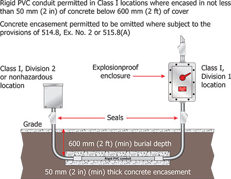
Use of certain types of non-metallic conduit in underground installations evolved from permission for use in bulk storage facilities in the 1950s to an exception that permitted the use underground in any facility with Class I locations in 1996. The permission provided in several of the special occupancies required that rigid PVC conduit be installed below a minimum of 600 mm (24 in.) of cover and converted to threaded metal 600 mm (24 in.) prior to the point where the bend to emerge from the earth occurred. Provisions to include the current exception into Article 501 permit Type PVC and Type RTRC conduit to be installed underground in any facility that includes Class I locations. That permission placed an additional restriction of 50 mm (2 in.) concrete-encasement on the underground installation of Type PVC and Type RTRC conduit where it was installed in a location not already addressed in Articles 511 through 515. The concrete-encasement provided some additional protection where normal activities within facilities are less predictable than those within the special occupancies (see figure 3 and Table 1 for further information on the evolution of wiring methods and on Type RTRC conduit).
Mineral-Insulated Cable (Type MI)
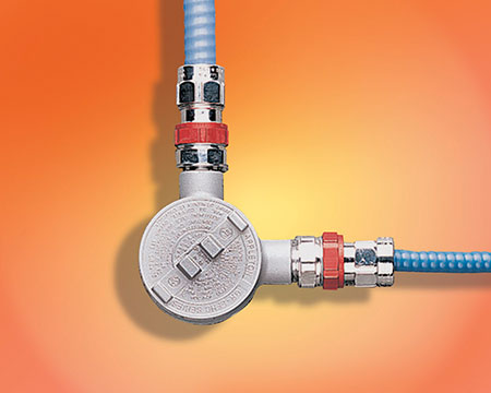
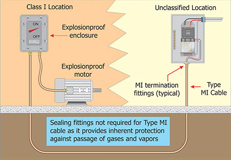
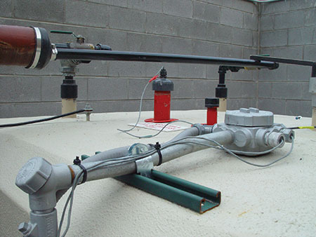
Type MI cable is a fairly unique wiring method. It is a factory assembly of one or more conductors insulated with a highly compressed refractory mineral insulation enclosed in a liquidtight and gastight continuous copper or alloy steel sheath. This type of cable is permitted to be used in Class I locations when the termination fittings are listed for this location. MI cable has multi-piece fittings that are threaded together when installed. The listing for the fittings ensures that these threaded connections result in an explosionproof assembly. Physical installation of the cable must be done in a manner to prevent tensile stress on these terminations (see figure 4 and photo 2). Where the outer sheath is made of copper, it must provide an adequate path to serve as an equipment grounding conductor. Where the outer sheath is made of steel, a separate equipment grounding conductor shall be provided.
The product standard used to evaluate these is UL 1203 Explosionproof and Dust Ignitionproof Electrical Equipment for Use in Hazardous (Classified) Locations. Fittings available in the marketplace are either listed as explosionproof or not listed as explosionproof. Unless the marking is visible after installation, it may not be obvious whether the fittings meet the requirements of the product standard.
Metal-Clad Cable (Type MC-HL)
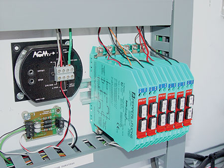
Type MC-HL is permitted in Class I , Division 1 hazardous (classified) locations. This is a multi-conductor, gas and vaportight continuous corrugated metal-sheathed cable provided with an overall polymeric jacket and an additional equipment grounding conductor sized in accordance with NEC 250.122. The termination fittings are specifically listed for Classes I , Division 1 locations. The Code currently permits any type of metallic sheath, but the product standard (UL 2225) limits the sheathing material to aluminum. Copper, copper-clad aluminum and aluminum conductors that employ thermoset or thermoplastic insulation are permitted as part of this type of cable assembly. The equipment grounding conductor is permitted to be insulated or bare. Cables are permitted to be rated up to 35 kV.
This type of cable is permitted in cable tray, in direct sunlight, and/or in direct burial or concrete encasement. The installation of MC-HL cable is limited by the Code to industrial establishments with restricted public access and facilities where the conditions of maintenance and supervision ensure that only qualified persons service the installation.
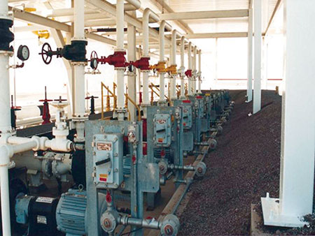
Where this wiring method is selected, the responsible decision-making party must be prepared to provide documentation to the authority having jurisdiction that those limiting conditions exist, and the AHJ must be prepared to evaluate the submitted documentation and determine if it meets the criteria specified for use of this method (see photo 3).
Instrumentation Tray Cable (Type ITC-HL)
Type ITC-HL is suitable for use in Class II, Division 1 hazardous (classified) locations. This is a multi-conductor, gas and vaportight continuous corrugated metal-sheathed cable provided with an overall polymeric jacket and may or may not include an additional equipment grounding conductor sized in accordance with 250.122 (see photo 5.04). The termination fittings are specifically listed for Class II, Division 1 locations. Cables are rated for 300 volts, but limited for use on circuits operating at 150 volts or less and 5 amperes or less [NEC, 727.1]. Instrumentation tray cable is evaluated for exposure to sunlight and may or may not be marked as sunlight resistant. This cable is permitted in direct burial applications or in concrete encasement. The installation of ITC-HL cable is limited by the Code to industrial establishments with restricted public access and facilities where the conditions of maintenance and supervision ensure that only qualified persons service the installation. Where this wiring method is selected, the responsible decision-making party must be prepared to demonstrate to the authority having jurisdiction (AHJ) through adequate documentation that those conditions do indeed exist (see photo 4).
Optical Fiber Cables
Optical fiber cables Types OFNP, OFCP, OFNR, OFCR, OFNG, OFCG, OFN, and OFC are permitted to be installed in raceways in accordance with 501.10(A).
Intrinsically Safe Systems
Intrinsically safe systems are covered by NEC 504. Where the circuits installed are intrinsically safe, as verified by the control drawings, the Code permits the use of any wiring method suitable for use in unclassified locations, including those permitted in Chapters 7 and 8 [NEC, 504.20]. These circuits are not dependent on the protection provided by the wiring method to prevent ignition of a flammable atmosphere. When the circuits are intrinsically safe, the energy is maintained at a level where it cannot ignite the atmosphere if the circuit is opened, shorted, or faulted to ground or other faults occur. Therefore, the wiring method is not limited. Although the wiring is not an ignition threat, due consideration should be given to the operation of the circuit. Should the circuit have a safety function that would be lost if the circuit were damaged, then the wiring method would become very important. The purpose is to ensure that the electrical system is not an ignition source. Even so, that may not be the only hazard that needs to be considered (see photo 5).
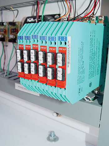
Therefore, it is extremely important to recognize the value and requirements of the control drawing for intrinsically safe systems. The control drawing is required for proper installation of these systems and is also necessary for making an inspection (see the annex for an example of a typical intrinsically safe system control drawing). Intrinsically safe systems include control drawings, and the zener diode barriers often reference a particular control drawing as well (see photos 6 and 7).
Identification
Other key requirements in Article 504 include rules for separation, identification, and conduit sealing. Intrinsically safe circuits are required to be identified at intervals not exceeding 7.5 m (25 ft) and must include the specific wording “Intrinsic Safety Wiring” (see figure 5). This identification requirement applies to raceways, cables, cable trays, and other wiring methods used for intrinsically safe system wiring.
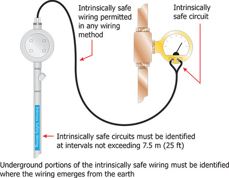
Identification labels must be located to be readily visible and traceable for the entire length of the wiring, except for any underground portions, which are re-identified as they emerge from the earth. Likewise, separate sections of this wiring created by walls, partitions, or other enclosures are required to be identified. Where a color code is used for intrinsically safe circuit conductors or wiring, such as raceways, boxes, and so forth, the color light blue is required [NEC, 504.80(C)].
Spacing Requirements
The Code permits any wiring method that is acceptable for an unclassified location to be used for intrinsically safe (IS) circuits. However, there are specific spacing requirements between IS circuits and those not instrinsically safe. The Code generally restricts IS circuits from being installed in the same raceway, cable tray, or cable with conductors of any nonintrinsically safe circuit. Conductors of intrinsically safe circuits are permitted where they are separated from nonintrinsically safe circuit conductors by a space of not less than 50 mm (2 in.) or by grounded metal partitions or insulating barriers. The concern here is the possibility of compromising the intrinsic safety of the circuit through inductive or capacitive coupling conditions related to close proximities of other wiring. The identification rules covered above help installers and facilities maintain initial spacing when additional wiring or systems are installed [see 504.30(A)(1) Exceptions and 504.30(A)(2)(1) through (4)].
Flexible Wiring in Class I, Division 1 Locations
When situations in an electrical installation warrant flexible connections in Class I, Division 1 locations, two options for the wiring methods are permitted: flexible fittings and flexible cord. The Code does not prescribe which option must be selected, but users must realize that this location has or could have ignitible concentrations of flammable vapors under normal operation. These days automation is evolving to a point where robots and mechanical devices are used to accomplish many tasks, even in hazardous (classified) locations. Movement of these mechanical devices requires more flexibility than was required in the past, which often necessitates the use of more flexible cords and greater lengths of flexible cord to complete electrical installations. In cases where increased use of robotics is employed, overall safety is improved because less human involvement is required to perform functions that were once extremely labor intensive. On the other hand, the use of flexible cord should always be minimized where other methods can be utilized to connect electrical circuits to equipment. The Code generally does not permit the use of flexible cord as a substitute for fixed wiring [NEC, 400.8(1)].
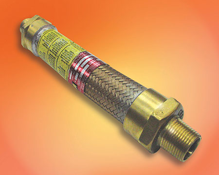
Explosionproof Flexible Fittings
Flexible fittings, sometimes called explosionproof flex, are available from several manufacturers in sizes 13 mm (½ in.) through 100 mm (4 in.). Standard lengths begin at 100 mm (4 in.) in smaller sizes and range to 900 mm (36 in.) for the larger sizes. These fittings are available with either male or female threaded end fittings. Some sizes are listed only for Groups C and D, while others are available for Groups A, B, C and D. These fittings are very rugged and suitable for physical abuse while providing flexibility for difficult installation or vibration of equipment. The product standard used to evaluate these fittings is UL 1203 Explosionproof and DustIgnitionproof Electrical Equipment for Use in Hazardous (Classified) Locations. (see photo 8).
Flexible Cord
Where flexible cord is installed as provided in 501.10(A) and 501.140, the cord must be listed for extra-hard usage and include an equipment grounding conductor A review of NEC Table 400.4 will provide a description of the cords that are considered extra-hard usage. Other limitations for use of those cords are also included in that table. The cords must be continuous; they must be supported or secured to prevent tension on the terminal connections; be terminated with a cord connector or attachment plug listed for the location and they must be sealed where they enter explosionproof enclosures or boxes to maintain the explosionproof integrity of the enclosure. Extreme care must be applied to select a fitting that matches the cord diameter to ensure that the explosionproof integrity of the enclosure is not compromised. As mentioned above, the provisions in 400.8 are applicable to cords installed in accordance with 501.140. It is important to consider all of the activities that take place on a normal basis that might subject flexible cords to physical damage and to provide proper precautions to protect the cord or cable where it is used.
Type TC-ER-HL Cable
Type TC-ER-HL cable is permitted as a flexible wiring method in industrial establishments with restricted public access, where the conditions of maintenance and supervision ensure that only qualified persons service the installation, for applications limited to 600 volts, nominal, or less, and where protected from damage by location or a suitable guard. Type TC-ER-HL cable is required to have an overall jacket and a separate equipment grounding conductor(s) in accordance with 250.122 [501.10(A)(2)(3)].
Excerpted from Hazardous Locations, Third Edition, Published by IAEI. All rights reserved.