The two previous articles in this series covered how currents are developed and handled in PV systems and how the ampacity of conductors is adjusted to deal with the unique nature of those currents. In this article, overcurrent protection for direct current(dc) and alternating current (ac) PV circuits will be addressed. Also, we will start the coverage on disconnecting means by looking at some odd things that happened on the way to the 2017 NEC.
PV Circuit Overcurrent Protection
Section 690.9 establishes the requirements for overcurrent protection associated with the now redefined PV system circuits, both dc and ac. Overcurrent protection requirements for batteries (energy storage systems), stand-alone PV systems, and dc and ac microgrids are covered in other articles in the Code and in a later article in this series.
Sometimes overcurrent protection is not needed. In any situation where the circuit conductors have sufficient ampacity for the sum of all available currents in that circuit under normal or fault conditions, overcurrent protection is not required [690.9(A)]
Special Consideration and Location. Although circuits are normally protected from overcurrents at their source of supply, that source needs careful definition (240.21). Some PV circuits differ from that general rule. Since several pieces of PV equipment such as PV modules, dc-to-dc converters, charge controllers and interactive inverters have current-limited outputs, circuits connected to those devices as sources require special consideration with respect to overcurrent protection. These circuits, when connected to another source that can deliver higher fault currents (e.g., utility source, energy storage systems and parallel-connected strings of modules) into that circuit than the current-limited source, shall be protected with an overcurrent protective device located at the higher current source end of the circuit [690.9(A)].
An Exception to 690.9(A) exempts the overcurrent device requirement on PV source circuits or dc-to-dc converter outputs, when the available short-circuit currents from all sources do not exceed the maximum overcurrent device current rating for a specific PV module or dc-to-dc converter.
Another Exception to 690.9(A) also exempts PV source circuits from overcurrent protection where there are no external sources of overcurrents from parallel connected source circuits or backfeed from inverters (and probably charge controllers). The backfeed capability of inverters under array fault conditions should be a specification in the inverter instruction manual. This specification may not be clearly stated in the instruction manual and a change to UL Standard 1741 may be required to clarify the requirement and define an appropriate test.
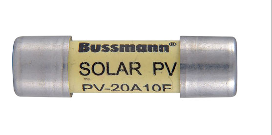
Rating. Most overcurrent devices used in PV systems will be rated at 125% of the maximum circuit current determined in Section 690.8 and where used in dc PV circuits, shall be listed for the PV application (photo 1). The overcurrent devices listed for the PV application will usually have a higher rated voltage, greater maximum operating temperature (50°C vs. 40°C for a standard OCPD) and have different time history curves.
In very rare cases, an overcurrent device in an assembly may be listed for continuous operation at 100% of its rating [690.9(B)]. DC breakers in an assembly rated at 100% are not used in PV systems. This 100% combination rating of the OCPD in an assembly should not be confused with the fact that UL Standards require that all overcurrent devices hold at 100% rating and blow/trip within one hour at 135% of rating. These tests are conducted on the bare (well ventilated) OCPD device without an enclosure. A load center, for example, is an assembly/enclosure and the circuit breakers installed in it are derated by the 0.8 factor (OCPD rating equals 125% of the maximum current) due to the internal heating provided by the circuit breakers themselves and the internal conductors.
Undefined Device. The adjustable electronic overcurrent protective devices addressed in 690.9(B)(3), 690.8(B), and 690.8(B)(3) appear to be adjustable trip circuit breakers and after setting per 240.6, they should be applied as any other circuit breaker. The author strongly feels that since they have no current-reducing function, other than the normal trip settings, they should not be used to directly establish conductor ampacity as apparently allowed by 690.8(B) and 690.8(B)(3).
“Circuit conductors shall be sized to carry not less than the larger of 690.8(B)(1) or (B)(2) or where protected by a listed adjustable electronic overcurrent protective device in accordance 690.9(B)(3), not less than the current in 690.8(B)(3).”
Section 690.8(B) appears to imply that these devices can reduce a high current to a lower current and then a smaller conductor associated with the lower current can be used when protected with this type of OCPD. As far as can be determined, there are no devices that can provide power circuit (branch circuit) overcurrent limitation/protection in this manner outside of some very sophisticated electronic devices. Hopefully the 2020 NEC will clarify this issue. The 2020 NEC may also define how actual current-limited inputs on some devices and energy management systems will deal with limiting the current from multiple sources connected to a single device or circuit. Look to Article 705 and 750 for changes in this area.
Optional Overcurrent Protection. Under the 2017 NEC, other than very small, solidly-grounded PV arrays, most of the dc circuits in PV source and PV output circuits will not be connected directly to earth (solidly grounded). In previous editions of the NEC, these ungrounded PV arrays (normally connected to non-isolated, utility-interactive inverters, would require an overcurrent device in both of the ungrounded circuit conductors (positive and negative) [2014 NEC, 690.9(E)]. Section 690.9(C) in the 2017 NEC, now permits the use of an overcurrent device (where overcurrent protection is required) in only one of these conductors, not both. And, if that option is selected, all dc overcurrent devices in other PV source and output circuits must be in the same polarity conductor in those circuits.
OCPD in Related Articles. Article 705 establishes additional requirements for overcurrent protection in the ac utility interactive inverter output circuits (still part of the PV system) where backfed circuit breakers are connected to the utility source. Article 710 does the same for the ac circuits in stand-alone systems. In general, conductors shall be protected from all possible sources of overcurrent (705.30, 705.65, and Article 240).
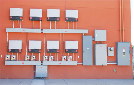
If circuit breakers are backfed, they shall be suitable for such operation [705.12(B)(4)]. This usually indicates that they will not be marked “Line” and “Load”. Also, if a backfed breaker is fed by a listed interactive source (PV utility-interactive inverter), the breaker does not have to be mechanically fastened to the panelboard [705.12(B)(5)]. However, where a backfed breaker is connected to the output of a stand-alone inverter (a voltage source and not interactive), that breaker shall be mechanically fastened to the panelboard in accordance with the requirements in 408.36(D) (photo 2).

Section 710.15(E) on stand-alone systems is not clear in this area, since it mentions that back-fed circuit breakers connected to an interconnected supply (interactive inverter?) require fastening, but the section does not address the output of a stand-alone (not interconnected) inverter. In Article 705, interconnected sources require or imply the use of interactive sources and those sources when connected to a back-fed breaker do not require that breaker to be secured.
The interrupt and short-circuit ratings of the equipment in an interconnected system shall consider the contributions from all sources (705.16).
Section 705.31 requires that an overcurrent device be located within 3 m (10 ft.) of the connection point of the PV ac output circuit to the service conductors in a supply-side connected PV system [705.12(A)]. This overcurrent device and an associated disconnect would usually be associated with the start of the feeder leading to the output of a utility-interactive inverter. An exception allows this overcurrent protection to be located more than 3 m (10 ft.) from the connection point if either a current-limiting circuit breaker or a cable limiter (photo 3) are installed at the connection point to the service conductors.
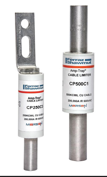
The author notes, that current-limiting circuit breakers have different mechanical and electrical characteristics than cable limiters. Where current-limiting circuit breakers have an overcurrent rating, include a disconnect function and will initiate a feeder to the inverter output at the breaker location, cable limiters have no overcurrent rating (they are sized/rated based only on the conductor size) and cannot provide that disconnect function. While both devices may be current limiting, the cable limited provides only a last-ditch protection before the cable melts under severe overcurrent conditions. The current-limiting circuit breaker provides that protection, possibly at a lower current limit and also provides the overload protection necessary to establish the start of a feeder.
Disconnect Oddities
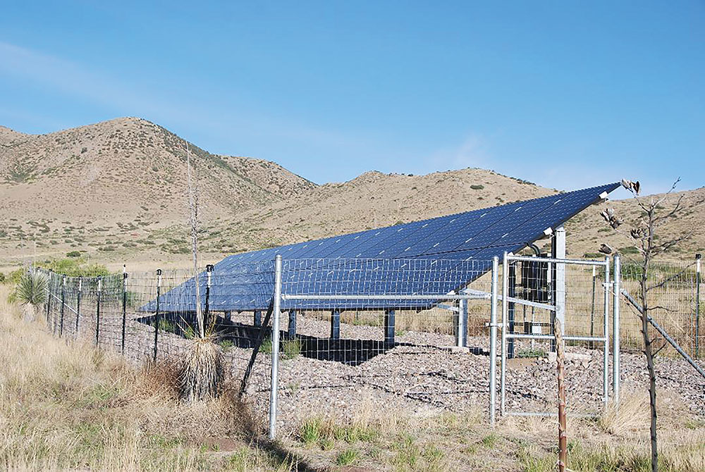
The various sections of the Code dealing with disconnects in PV systems have been significantly revised in the 2017 NEC. As shown in Figure 690.1(b), the PV system disconnect can be either ac or dc and is the demarcation between the PV system and any other source of energy including the utility grid, energy storage systems, and other energy sources like fuel cells or wind systems. Section 690.13 deals primarily with the PV system disconnect, and Section 690.15 establishes requirements for the disconnection of PV equipment (photo 4).
The following comments are intended for those that are interested in looking into the Code in some depth and hopefully will prompt some technical interchanges on these subjects as well as food for thought on comments to the first and second drafts of the 2020 NEC.
No Longer at the Point of Entry. Section 690.13(A) requires that the PV system disconnect be located in a readily accessible area and this may be a dc disconnect in some systems or an ac disconnect in others [see NEC Figure 690.1(b)]. Note that, there is no longer a specific requirement for a dc PV disconnect to be located inside or outside nearest the point of entry of the dc conductors into the building as required by the 2014 and previous editions of the NEC [690.13(A), 2014 NEC] (photo 5). Where the conductors were installed in a metal raceway [690.31(F), 2014 NEC], an Exception permitted the PV disconnecting means to be remote from the point of entry and, except for bathrooms, that dc PV disconnect could be located anywhere in a readily accessible area.
While there is a requirement (690.15, 2017 NEC) for an dc isolation device or dc disconnect within 10 feet of the utility-interactive inverter, that device may not be located at or near the point of entry of the dc conductors if the inverter is more than 10 feet from that point of entry. Of course, the dc conductors inside the building are still required to be in a metal raceway or installed in Type MC cable [690.31(G)], but there is no longer an exception in 690.13 related to that installation requirement that allows nearly any location for the PV system disconnect.
An Informational Note to 690.13(A) alludes to the 690.12 Rapid Shutdown System as dealing with energized conductors entering the building, but the author feels that this a separate system/function that is not directly related to the widespread requirement of having all power sources equipped with a disconnect as the conductors enter a building [230.70(A)(1)]. This issue may or may not be addressed by the 2020 NEC.
While some AHJs and jurisdictions may continue to follow the 2014 NEC guidance in this area, the 2017 NEC apparently allows/accepts the required dc isolation device/disconnect on the dc input of the inverter or the input to a charge controller as a suitable dc PV disconnect, no matter where it is located. And, as long as that location is readily accessible, this disconnect can also serve as the PV system disconnect where it meets the definition and requirements of that device. In some cases, the disconnect may be the PV system disconnect as defined in the 2017 NEC and in other cases, it may just be a dc disconnect at the input to a utility-interactive inverter.
Disconnect Required at the PV Array? In previous editions of the Code, Section 690.13(E) 2014 NEC stated that a PV disconnecting means is not required at the PV module or array location. That section is missing from the 2017 NEC, and 690.15 requires an isolating device for all conductors not solidly grounded within 3 m (10 ft.) (or in the equipment) for PV modules, ac PV modules, and dc-to-dc converters along with other equipment. Connectors are allowed to meet the isolation device requirement, but where maximum circuit current is greater than 30 amps, the output of a dc combiner must have a disconnecting means (e.g., switch or circuit breaker) [690.15, 690.15(D)]. Although there is no specific requirement that the isolating device/disconnect be accessible, it should be noted that while most module connectors are not accessible on many rooftop installations, the disconnecting means associated with the output of a dc combiner would normally be accessible on the roof because of servicing requirements for the combiner. Numerous changes are being proposed in these two sections for the 2020 NEC and hopefully, the intent of the various disconnect requirements will be clarified and further simplified.
To Open the Grounded Conductor or Not? Since the PV system disconnect may be the connection of the output a utility-interactive inverter to the utility power source, the requirements of disconnects and Article 690 should be consistent with those requirements in Article 705. The requirements in 690.13(F) require that the PV system disconnect simultaneously open all conductors of the PV circuit connected to other sources. There is no exception for grounded conductors and it is noted that in many cases where a grounded conductor is involved (usually a neutral) in that circuit, at least a three-pole disconnecting means would be required. It will be difficult to achieve the ac PV system disconnect using the backfed circuit breaker in a load center due to that neutral switching requirement. On the other hand, Section 705.21 requires that only the ungrounded conductors be disconnected at this point.
Proposals have been made to correct the requirement in 690.13 in the 2020 NEC; but in the meantime, it is suggested that the requirements of 705.21 be followed rather than those of 690.13(F). A TIA for the 2017 NEC may rectify this issue before the 2020 NEC is published and adopted.
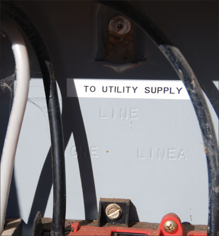
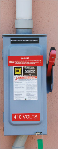
Marked “Line” and “Load,” To Backfeed or Not? AHJs have noted that many of the utility-required ac PV disconnect switches (visible blade, lockable open) have terminals marked “Line” and “Load,” but are being backfed because the utility connection should be made to the touch-shielded, protected, upper “Line” terminals (photo 6). Section 690.13(F)(2) states:
“(2) Devices marked “line” and “load.” Devices marked with “line” and “load” shall not be permitted for backfeed or reverse current.”
This section appears to confirm the requirement that switches (as devices) so marked, should not be backfed. However, Section 705.12(B)(4) provides slightly different guidance:
“(4) Suitable for Backfeed. Circuit breakers, if backfed, shall be suitable for such operation.
Informational Note: Fused disconnects, unless otherwise marked, are suitable for backfeeding.”
Discussions with personnel at Underwriters Laboratories (UL) add additional weight to the Informational Note and confirm that there are no issues with backfeeding fused or unfused switched disconnects unless they are specifically marked with words “Not suitable for back feeding” or the equivalent. The “Line” or “Line” and “Load” markings on these switches are used to identify the shielded, protected terminals where the utility (or other most likely energized circuit when the switch is opened) is to be connected. Proposals for the 2020 NEC should clarify this area.
Summary
The ratings and application of overcurrent protective devices (OCPD) in PV dc and ac circuits are relatively straightforward. Some PV source circuits, where several conditions are met, can be installed without OCPD. Consideration should be given to circuits where a current-limited source is connected to a source with a much higher available fault current and in these circuits the OCPD should protect the circuit conductors at the source of that higher current. In general, all circuits should be protected for overloads and fault currents from all sources and the OCPD providing this protection should have appropriate ratings.
The requirements for disconnects in PV systems in the 2017 NEC are still in a state of flux as we learn how they should be applied. Common sense should prevail as these inconsistences are identified and worked out, either through TIAs to the 2017 NEC, information and clarifications from Underwriters Laboratories, or even changes for the 2020 NEC.
For More Information
The author has retired from the Southwest Technology Development Institute at New Mexico State University, but is devoting about 25% of his time to PV activities to keep involved in writing these “Perspectives on PV” articles in the IAEI News, and to stay active in the NEC and UL Standards development process. Seven- to eight-hour presentations are still available on PV and the Code, and they cover 2011-2017 NEC requirements. He can be reached at: e-mail: jwiles@nmsu.edu, phone: 575-646-6105
The Southwest Technology Development Institute web site maintains a PV Systems Inspector/Installer Checklist and all copies of the previous “Perspectives on PV” articles for easy downloading. A color copy of the latest version (1.93) of the 150-page, Photovoltaic Power Systems and the 2005 National Electrical Code: Suggested Practices, written by the author, may be downloaded from this web site: https://swtdi.nmsu.edu/codes-standards/
LATE BREAKING NEWS.
John Wiles will be making three of his all-day PV and The NEC presentations on the East Coast in March.
Sponsored by the IEC-Chesapeake, they will be held in Dulles, VA on March 6th, Wilmington, DE on March 7th, and on March 8th in Laurel, MD.
See details on this web link: https://www.iecchesapeake.com/pv-the-nec?journal=303
For more information and registration, contact 301-621-9545. Early registration ends on February 6, 2018.